
pdi使用手册
1.shatterIt feature(破碎物体):Num shards:破碎面数shatter styleuniform(统一):就是整体破碎的意思。
pivot based。
radial(径向):Num rings是破碎的环数noise是噪波值radial axis:是径向的轴向:S(shortest)是以最短的边来径向破碎。
M(medium)是以中心来径向破碎。
L(longest)是以长边来径向破碎,path based(基于路径来破碎):可用曲线来画路径,然后在按select path来选择该路径,就会沿路径来破碎了。
original geometry(原几何体)hide是隐藏remove是移动create pdi object from fragments是从碎片中创建pdi 物体。
assign new material to cut faces是设计新的材质在被切的面上。
在材质窗口可以看见一个绿色的材质。
2.create pdi body(创建pdi物体):none:无的状态可以对破碎物体进行任意的移动,其他状态不可以随便移动,即便移动了,还是变回原来的位置。
capsule(胶囊):破碎物体周围出现胶囊状的网格线条,这样破碎物体破碎运动的时候会破碎得比较开一点。
让碰撞更加有弹力,同时,他是破碎碰撞也是基于胶囊状网格的。
convex hull:它的破碎是基于破碎的边缘或者边缘线的。
相对于胶囊破碎的来说,它破碎的范围没有那么广,比较密集的。
mesh:这是网格破碎,是比较精密准确的一种破碎,破碎的时间比较长。
auto:自动,做挡板作用的物体要够被动(passive)按钮。
(1)flip collision side:是轻击碰撞边缘(2)animated:动画的。
passive:是被动的意思的,当选中某个物体时,勾选自动后,再勾选被动,该物体就变成类似于挡板的作用,破碎物体碰到,会反弹,就破碎到该物体了上了。
active at first hit(自动产生第一次碰撞):就是当破碎物体碰撞到被动物体时,会和被动物体发生反应,破碎物体碰到被动物体后,和被动物体一起落下。
3.pdi dynamics properties(Pdibounciness:弹力firction;摩擦力,摩擦力越大,阻尼值越大。
linear damping:线性阻尼angular damping:有角度的阻尼gap factor:间隙系数,该值越大,碰撞后弹开的间隙越大,就会弹得越远。
mass:质量mass centre:质量中心动力学参数):inital velocity:初始化速度value:速度值random:速度随机值initial spin(初始化旋转):value:旋转值random:旋转随机值affects force fields(力场的影响):勾选后,就会受maya力场的影响。
选中破碎物体后,勾选后,按include/exclude,accept接受后即可。
4.pdi solver options(Pdi物体的解算选项):number of threas(线程数):一般默认为2fits units to maya gird和enable cached mode一般都是要勾选的。
gravity(重力):勾选disabled后就没有重力了substep:精确度,一般为10以下为好。
5.manage pdi world(Pdi 物体管理器):(1):把物体创建为Pdi物体时,在manage pdi world,按add键来添加这些pdi物体,remove 和remove all这两个按钮只是让物体消失在pdi物体管理器而已,并不是真的把这些pdi物体删除。
delete selected是删除你所选择的pdi物体delete all pdi nodes是删除所有的pdi物体。
(2);pdi basic fractures按创建(create)可以把破碎的物体创建为一个整体,这时破碎的物体的边线是为蓝色的。
switch on/off stresses view是打开或者关闭压力视图,即打开后,破碎物体会有白色和蓝色的面出现,白色代表破碎的强度大,蓝色代表破碎的强度比较小。
disabled:勾选后,物体碰撞后,不会发生反应,只是会穿过该物体。
torsion:勾选后,物体碰撞后会产生反应。
hardness:设置物体本身的硬度,硬度越大,碰撞产生的碎块就越少,反之亦然。
clusterize:聚集度,聚集度为0时,破碎的聚集度是最大,即破碎物体几乎为一个整体,聚集度为100时,破碎物体为最分散,容易破碎。
continuous:持续碰撞local:局部碰撞mass:质量的设置friction:摩擦力的设置bounciness:弹力的设置initial velocity:初始化速度inital spin:初始化旋转的角度affects force fields:力场的影响,勾选后可以用maya的力场来控制物体。
6.在dynamics模式下,effects里有maya的特效,里面也有破碎特效effect-create shatter,制作出的破碎物体也可以作为pdi物体来使用,能很好的和maya的特效进行融合。
7.pdi advanced fractures(pdi高级破碎参数):在破碎物体选中其中一个破碎的面体,然后在fragments(碎片)窗口会显示该面体的名称,选中名称,会再stresses(压力)窗口会出现与该面体相连接的面体,selected all后,所有相连的面体都会被选中,invert selection就是反选的意思。
选择全部的面体后,在调节break treshold的值后,会出现于该面体相连的面体会有聚集的现象,碰撞时很难分开,就像被吸附一样。
break energy也是一样,这两个值越大,聚集的现象越大,越难分开。
break treshold是使面体显示为黑色的break energy是使面体显示为红色的。
break at frame:是在某个帧来破碎。
8.bake pdi simulation(烘焙仿真pdi物体):linear threshold(线性阈值)和angular threshold(角度阈值)一般是保持默认值就可以了,单击default treshold for saving resources,这时就是默认值了。
然后再按bakepdisimulation进行烘;--deleteallpdinodes(删除所有;--deleteallpdikeys:是删除所有;9.注意:在保存之前,你的动画帧数在某个帧,而并;pulldownit使用注意事项及其心得:;(1);FBX格式问题分析;fbx是Maya和max的共用格式,带相机,动画;一①必修将Maya和max帧速率,渲染然后再按bake pdi simulation进行烘焙即可--delete all pdi nodes(删除所有的pdi节点):删除节点后,之前做的动画会消失,只是静止在删除前的破碎状态,这样就可以做出破碎的静止物体了。
--delete all pdi keys:是删除所有烘焙后物体留下的关键帧。
9.注意:在保存之前,你的动画帧数在某个帧,而并非是第一帧,但是当你下次打开的时候,会自动回到第一帧的,这是属于正常的现象。
pulldownit使用注意事项及其心得:(1)FBX格式问题分析。
fbx是Maya和max的共用格式,带相机,动画。
一①必修将Maya和max帧速率,渲染时间,渲染尺寸,相机的焦距和镜头长度设为一样;②渲染尺寸max中必修使用自定义(custom 720*576 1.250:1.000)使其像素比保持一致,然后Maya中需将相机的参数设置为和max一致。
二①导出fbx格式应注意所有物体的命名和动画,最好另命名所有物体包括组的命名,不然导入新场景与其重名的物体会被替换,导致模型,动画出错。
②导出fbx文件时注意存放路径不能带中文,命名也不能带中文或纯数字命名。
③面过多的模型需将模型降低细分,不然会增加系统负担(文件过大maya导入FBX格式会很慢)三①max相机和Maya相机互导,max相机带动画导出时应注意:②Maya带动画物体导出应注意四Maya和max文件用fbx格式互导时,必修保持(导入\导出)版本保持一致五如果是蒙皮动画(一般没问题),但如果不行(常见的是骨骼在动,而模型不动),可见模型做点缓存,具体设置为:maya切换到animation模块,Geometry cache\creat New cache 然后在max里面导出以后给角色模型添加Pointcache修改器然后load之前maya导出的cache (摘自互联网)六导出fbx若带贴图勾选Embed media七maya可以混合建模,曲面+细分+多边形,但max只对多边形支持最好所以想将maya模型导到max需将模型完全转成多边形对象再导出就行,用Convert转,如果是nurbs曲面模型最好先转成Subdivision细分后再将其转成polygon导入obj即可保证全是四边面。
从maya导入的模型是黑色的:法线反了;场景有灯;(2);一pdiMaya物体导出时需将其所有的属性删干净;二带动画的pdi物体需将其烘焙成关键帧,删掉刚体;三注意如果导入到Maya中还是出现动画乱跳,碎块;rayfiretoolfor3dmax破碎插件支;从maya导入的模型是黑色的:法线反了;场景有灯,默认灯关掉;贴图丢失;材质本是黑色的;默认材质没有关联;导入出错。
(2)一pdi Maya物体导出时需将其所有的属性删干净,全部的命名须另命名二带动画的pdi物体需将其烘焙成关键帧,删掉刚体属性,另命名后导出,否则重名的物体碎块会乱飞。
三注意如果导入到Maya中还是出现动画乱跳,碎块乱飞的问题,可见其另存为Maya格式的(ma\mb)导入Maya场景中。
rayfire tool for 3dmax破碎插件支持大型场景,碎块形态真实易操作,但是要用grayfire tool 做动力学解算,必修装PhysX,这是基于N卡机子而言的,所以只能碎开,如果将碎开的物体导出fbx文件,在maya调整修改(如分离面)即便删除历史记录,重新打组再导入max会有重面现象。
建议如果用rayfire tool插件,就用max实现破碎,这样就不会出现重面现象。
也操作方便,避免了互导的麻烦。
PDI检查操作规范

经销商售前车辆管理流程经销商售前车辆管理流程图:正常销售功能性质损:售前索赔储运质损:运输索赔经销商售前车辆PDI 检查总则:1. 对于所有交付客户之前的销售车辆,进行100%检查。
2.所有PDI 检查人员必须经培训并取得资格证书方可上岗。
3.PDI 检查前,车辆必须按照规定的程序进行洗车。
4.为避免天气和阳光变化而引起检查结果的变化, PDI 在规定的场地进行,或类似的亮度条件下进行, 场地要求如下:检验场地应在室内或遮阳棚下进行. 室内或棚内灯光强度在车辆腰线处大于1100Lux.5.PDI 检查流程:见下列流程,分为“动态检查”和“静态检查”部分PDI 检查推荐分车内/ 车外两名检验员;如果是一人则应保证覆盖所有检查内容外观检查应离车1 米。
必须用气压计检查轮胎气压应符合规范要求。
缺陷判断标准根据《售前车辆缺陷判断标准》判定。
将检查结果填写在《售前检查单》上,并将相关信息上报。
6.PDI 整个检查流程时间视车辆复杂程度控制在20 分钟左右三.PDI检查基本操作流程2.检查左前翼子板,左前门、 防擦条、后视镜等表面与配 合;4.进入副驾驶座,检 查座椅,遮阳板等内 饰以及前档玻璃表 面;5.检查车辆右侧表面质量与配合,包括右前后门, 前后翼子板和加油小门;1.根据售前检验单,核对选装单 上的有关信息, 以及VIN 号的一 致性; 2.钥匙通电,待车辆 自检结束,启动车 辆,观察各种指针、 指示灯是否异常;3.系安全带,检查安全带指示灯是否熄 灭;5.停车熄火,拔出 钥匙,完成检查,亠 ------- L4.将车开到PDI 检验棚, 同时检查方向盘、转向、 悬挂、刹车是否异常;< 1——静态检查: 1.1打开前盖,检查 发动机舱: 瓶、标签, 盖松紧等,包括 电 液位,旋 关刖盖;1.2站在车前部:检查 A 前盖表面,车前灯光等7.检查后档加热、行李箱, 检查后盖,后保,尾灯功 能及表面质量等;6.检查后排座椅以 及相关内饰功能与 表面配合,检查后档 玻璃;8.检查左后门,左后翼 子板表面与配合,后排 座椅情况; 9.绕车检查:轮胎的 型号、胎压、鼓包,漏水,钥匙的防盗, 遥控、门锁等。
PDI检查作业指导书(加入总检路试内容)

2、观察机油尺
操作、目测
2
加速踏板
卡滞、不灵活、异响
1、踩加速踏板后,观察踏板运动
操作、目测
3
转向柱管及方向盘
连接松动、受阻、转向沉重
1、转动方向盘
操作
5
离合器、变速箱及挂档系统
分离踏板重、异响、不回位、换档受阻、无倒档、跳档
1、检查离合器踏板高低位置、自由行程及回位
2、踩住离合器到底,将所有档位挂一遍
操作、耳听
14
空调系统检查
不制冷、制冷剂泄露、异响
1、打开AC开关,观察AC开关指示灯、车辆抖动状况、听是否有异响
操作、耳听
15
蓄电池
观察孔发黑、电极柱腐蚀、锈斑、桩头松动、破损
1、检查电瓶观察孔
2、检查电瓶外观
目测
五、底盘检查项目
序号
检查内容
缺陷特征
操作
方式
1
冷却液、机油、制动液、洗涤液
漏液、渗液、液面偏低
一、外观检查项目
序号
检查内容
缺陷特征
操作
方式
1
钣金表面
三伤
1、观察车体表面
目测
2
漆表面
磕、碰、划伤,色差、桔皮、杂漆、气泡、流痕(流漆)、遮盖不良、凹陷、颗粒
1、观察车体表面
目测
3
整车玻璃
胶痕、划伤
1、观察玻璃
目测
4
前、后保险杠、前格栅
磕、碰、划伤
1、观察前、后保险杠
2、观察前格栅
目测
5
镀铬徽标、文字商标
操作、目测
8
雾灯、制动灯、倒车灯
不亮,接触不良,失效
《PDI作业指导书》(doc)
《PDI作业指导书》(doc)引言概述:PDI(Pentaho Data Integration)是一款开源的ETL(Extract, Transform, Load)工具,广泛应用于数据仓库、数据集成和数据转换等领域。
本文将为大家提供一份PDI作业指导书,旨在帮助用户更好地理解和使用PDI,提高数据处理效率和质量。
一、PDI简介1.1 PDI概述PDI是Pentaho公司旗下的一款数据集成工具,具有强大的数据提取、转换和加载功能。
它支持多种数据源,包括关系型数据库、文件、Web服务等,能够高效地将数据从不同源头抽取出来,并进行灵活的转换和加载操作。
1.2 PDI的优势PDI具有以下几个优势:1.2.1 易于使用:PDI提供了直观的图形用户界面,用户可以通过简单的拖拽和连接操作来构建数据处理流程,无需编写复杂的代码。
1.2.2 强大的转换能力:PDI提供了丰富的转换步骤和功能,包括数据清洗、数据过滤、字段计算等,用户可以根据实际需求进行灵活的数据转换操作。
1.2.3 可扩展性:PDI支持插件机制,用户可以根据自己的需求开发和集成自定义的插件,扩展PDI的功能。
1.3 PDI的应用场景PDI广泛应用于以下几个领域:1.3.1 数据仓库:PDI可以帮助用户从不同的数据源中抽取数据,并进行清洗、转换和加载,构建高效的数据仓库。
1.3.2 数据集成:PDI可以将不同系统中的数据进行集成,实现数据的统一管理和共享。
1.3.3 数据转换:PDI可以对数据进行各种复杂的转换操作,如数据格式转换、数据合并等。
二、PDI的安装与配置2.1 安装PDI2.1.1 下载PDI:访问Pentaho官方网站,下载适合自己操作系统的PDI安装包。
2.1.2 安装PDI:运行安装包,按照提示完成PDI的安装。
2.2 配置PDI2.2.1 配置数据库连接:打开PDI,进入“文件”-“数据库连接”,配置数据库连接信息,包括数据库类型、主机名、端口号、用户名和密码等。
人蛋白质二硫键异构酶(PDI)说明书

人蛋白质二硫键异构酶 (PDI)试剂盒使用说明书--上海谷研生物公司专业代理销售本试剂盒仅供研究使用。
检测范围:1.5pg/ml-40pg/ml使用目的:96T本试剂盒用于测定人血清、血浆及相关液体样本中蛋白质二硫键异构酶(PDI)含量。
实验原理本试剂盒应用双抗体夹心法测定标本中人蛋白质二硫键异构酶(PDI)水平。
用纯化的人蛋白质二硫键异构酶(PDI)抗体包被微孔板,制成固相抗体,往包被单抗的微孔中依次加入 蛋白质二硫键异构酶(PDI),再与 HRP 标记的蛋白质二硫键异构酶(PDI)抗体结合,形成抗体 -抗原-酶标抗体复合物,经过彻底洗涤后加底物 TMB 显色。
TMB 在 HRP 酶的催化下转化 成蓝色,并在酸的作用下转化成最终的黄色。
颜色的深浅和样品中的蛋白质二硫键异构酶 (PDI)呈正相关。
用酶标仪在 450nm 波长下测定吸光度(OD 值),通过标准曲线计算样品中人蛋白质二硫键异构酶(PDI)浓度。
试剂盒组成1 30 倍浓缩洗涤液 20ml×1 瓶 7 终止液 6ml×1 瓶 马上进行试验,可将标本放于-20℃保存,但应避免反复冻融2.不能检测含 NaN3 的样品,因 NaN3 抑制辣根过氧化物酶的(HRP )活性。
操作步骤1.标准品的稀释:本试剂盒提供原倍标准品一支,用户可按照下列图表在小试管中进行稀释。
40pg/ml5 号标准品 150µl 的原倍标准品加入 150µl 标准品稀释液 2. 加样:分别设空白孔(空白对照孔不加样品及酶标试剂,其余各步操作相同)、标准孔、待测样品孔。
在酶标包被板上标准品准确加样50µl,待测样品孔中先加样品稀释液40µl,然后再加待测样品10µl(样品最终稀释度为5 倍)。
加样将样品加于酶标板孔底部,尽量不触及孔壁,轻轻晃动混匀。
3. 温育:用封板膜封板后置37℃温育30 分钟。
PD-I激光测距仪作业指导书
PD-I激光测距仪作业指导书1.目的规范PD-I激光测距仪的操作程序,保证正确使用仪器,保证检测工作的顺利进行和设备安全。
2.适用范围PD-I高精度手持式激光测距仪不仅可以准确快捷的用来测量距离,计算面积和体积,而且更方便、安全、可靠,尤其在测量较远距离时。
因此被广泛应用于以下领域:建筑工程、内外装修、舞台布置、房屋验收鉴定、测绘行业、林业、市政工程、交通事故现场测量等。
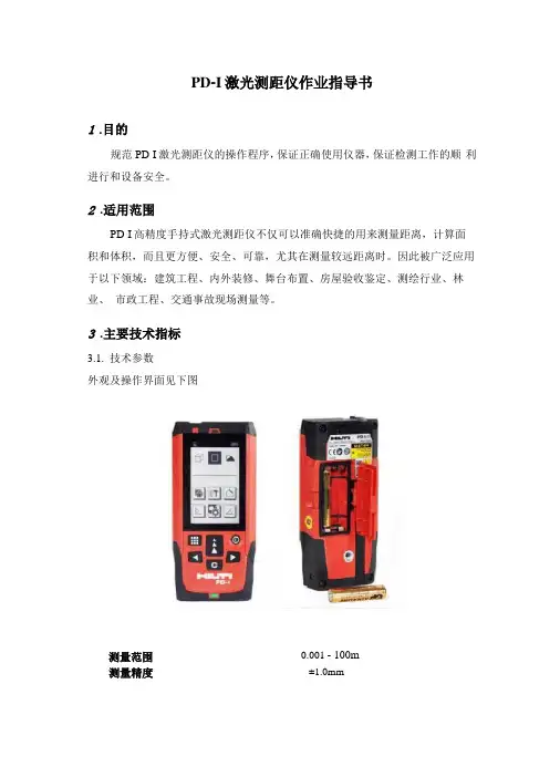
3.主要技术指标3.1.技术参数外观及操作界面见下图0.001 - 100m测量范围测量精度±1.0mm3.2.性能特点4.操作规程4.1.主要功能键4.1.1开关机启动:短暂按启动键。
在按动下个按键前,电池的显示会一直显示在显示屏上的。
关闭:按住关闭键直到仪器关闭。
为了延长电池的使用寿命,在3分钟内未触摸任何键盘时,激光将会自动关闭。
6分钟后仪器将会自动关闭。
4.1.2清除键使用清除键回到上一指令。
在测量面积或体积时,可以用清除键清除单个测量结果,重新进行测量。
4.1.3照明按住照明键,显示屏上的照明会开启或关闭。
在关闭仪器时,灯也会关闭。
4.1.4测量基准边在固定挡板打开时,仪器能自动识别测量基准边,并设置测量基准边以使得到正确的测量值。
测量基准边的标准设置是后沿。
按测量基准边键,可将测量基准边一次性地设置为从这个边出发的测量。
在测量后测量基准边会自动还原为以后沿为基准的设置。
也可以将测量基准边常设为前沿,较长时间按测量基准边-键{A,8}来完成此设置。
较长时间按测量基准边-键{A,8},将测量基准边返回到后沿。
4.2.测量4.2.1单个距离测量按DIST键开启激光。
再按此键进行测量。
测量结果将显示在显示屏上。
4.2.2最大/最小值测量这个功能可以提供从某一点出发来进行的最大或最小值的测量。
用于确定到墙角的距离(最大值)或垂直距离(最小值)等用法。
按住DIST键,直到听到峰鸣声。
缓慢地在目标周围大范围的移动激光,例如:房间的一角。
PDI

DIN ISO9002、EN2 9002标准
捷达轿车交车检查(PDI)
2002版
修理单号底盘号发动机代码车辆接收(检验)单位车辆维修单位
务必使用保养维护手册
合格=已检查未发现缺陷
不合格=检查中发现缺陷
消除=按维修信息消除缺陷
上述工作完成后,在维修保养手册上填写好交车检查证明(PDI)记录
消除所有缺陷,并将此表存档
备注:
DIN ISO9002、EN2 9002标准
宝来轿车交车检查(PDI)
2002年版
修理单号底盘号发动机代码车辆接收(检验)单位车辆维修单位
务必使用保养维护手册
合格=已检查未发现缺陷
不合格=检查中发现缺陷
消除=按维修信息消除缺陷
上述工作完成后,在维修保养手册上填写好交车检查证明(PDI)记录
消除所有缺陷,并将此表存档
备注:。
PDI模块型紧凑型远程电源分布面板规格说明(版本002,6 1 2017)说明书
Guide Specifications (Revision 002, 6/1/2017)1GENERAL1.1SummaryThese specifications describe requirements for a remote power panel (RPP) distributing power to sensitive loads. These specifications apply to the North American market.1.2StandardsThe PDI Modular Compact RPP shall be certified through ETL for the following standards:∙UL 60950∙UL 891∙CS 22.2In addition, the Modular Compact RPP shall be designed, manufactured, tested, and installed in compliance with the following standards:∙NFPA and specifically NFPA-70E∙UL67∙UL50∙UL489∙UL891∙IEEE 519-1991∙ANSI C33.4∙NEMA ST-20∙NEMA AB-1∙NEMA-PB-1∙NEC∙ISO 9001The PDI Modular Compact RPP shall comply with the latest FCC Part 15 EMI emission standard for Class A computing devices.1.3System Description1.3.1Environmental RequirementsThe Modular Compact RPP shall have the following environmental requirements for operation and storage requirements:∙Temperature ranges:o Storage: -67° to +185°F (-55° to +85°C)o Operation: +32° to 104°F (0° to 40°C)∙Relative Humidity: 0% to 95% non-condensing∙Operating altitude: Up to 6,600 ft. (2,000m) above Mean Sea Level; the unit is de-rated if operated above this altitude.______________________________________________________________________________________________________________Guide Specifications (Revision 002, 6/1/2017)∙Audible noise: The audible noise level less than 45 dBA.∙Storage and transport: Up to 40,000 ft. (12,200 m) above Mean Sea Level.1.3.2Electrical RequirementsThe Modular Compact RPP shall accept input power rated at 225A, 400A, and 450A.At 60 Hz, input/output voltages shall be 3-phase, 4-wire plus ground AC at 208/120V, 60 Hz; or400/230V, 60 Hz; or 415/240V, 60 Hz; or 480/277V, 60 Hz.At 50 Hz (IEC), input/output voltages shall be 3-phase, 4-wire plus ground AC at 380/220V, 50 Hz; or 400/230V, 50 Hz; or 415/240V, 50 Hz. Input and branch circuit breakers shall allow 4-poles enabling neutral as an optional requirement.1.4Documentation1.4.1DrawingsModular Compact RPP 1-line electrical drawings and outline drawings shall be furnished.1.4.2Installation and Operations DocumentationA Modular Compact RPP Installation and Operations manual shall be furnished. Points lists (Modbus register maps) for panelboard and main feed monitoring shall be available for downloading from the PDI website.1.4.3Spare PartsA list of recommended spare parts shall be made available at customer request.1.4.4Contact ListA contact list for PDI functions, such as Service and Accounting, shall be provided.1.5WarrantyThe manufacturer shall provide a 12-month warranty against defects in material and workmanship for 12 months after initial startup or 18 months after shipping date, whichever comes first.1.6Quality AssuranceThe PDI Modular Compact RPP shall be designed and manufactured according to internationally recognized quality standards, including those listed in section 1.2 Standards. The manufacturer shall be ISO 9001 certified.______________________________________________________________________________________________________________Guide Specifications (Revision 002, 6/1/2017)The PDI Modular Compact RPP shall be factory tested before shipment. Testing shall include at minimum:∙Quality control checks specific to the unit and its configuration, including function testing to determine that the unit functions as designed.∙Hi-Pot Test at two time s the unit’s rated voltage plus 1000 volts, per UL 60950 requirements.∙Calibration tests for monitoring.∙Tests for alarm annunciation as designed and/or as the customer requests.______________________________________________________________________________________________________________Guide Specifications (Revision 002, 6/1/2017)2PRODUCT2.1Components2.1.1EnclosureThe cabinet enclosure shall be constructed of steel. The cabinet shall be a NEMA Type 1 enclosure and shall meet IP20 requirements.Front maintenance only The Modular Compact RPP shall require only front access for service and all routine maintenance. Adding or replacing power distribution cables and circuit breakers shallrequire only front access. Replacing monitoring components or wiring communications shall require only front access.Cabinet dimensions Enclosure dimensions shall be 23.75" W x 84" H x 12.68" D, including doors.The unit footprint shall be 12" x 24" and shall allow a back-to-back two-unit modular cluster to fit in a 24" x 24" floor tile opening.Weight Modular Compact RPP weight shall be approximately 225 lbs. for a typical unit. Maximum weight shall be 300 lbs.Cooling The unit shall be convection cooled and shall have no fans. Heat rejection shall be through front ventilation openings. Convection cooling shall be sufficient for full load operation.Clearances The Modular Compact RPP shall require the following clearances:∙Front: 36" (service and ventilation)∙Top: 18" (ventilation)∙Underfloor 12" (cabling clearance if bottom entry)Compartments The Modular Compact RPP enclosure shall have three (3) compartments that are separately accessible from the front. Low- and high-voltage components shall be segregated into separate compartments.∙The top (input) compartment shall allow 1 or 2 main feeds to panelboards or main lugs only connections, optional circuit breaker locks for a manual dual system, and an optional SurgeProtective Device (SPD) (or Transient Voltage Surge Suppressor (TVSS)).∙The middle (display/control) compartment shall contain low-voltage components, including an optional color touchscreen display on the front door with monitoring components in theinterior. The door of this compartment shall have an optional USB port for configuringmonitoring software. Optional Kirk Key® synchronization components shall be in thiscompartment and the input compartment.∙The bottom (output) compartment shall allow (1) 84-pole or (2) 42-pole panelboards. The bottom compartment shall alternatively allow 36-pole or 72-pole IEC panelboards.Doors Each compartment shall have its own lockable hinged door on the front of the unit. Eachcompartment’s door shall be able to be opened independently of the other doors. The doors shall be hinged on the left or the right, which must be selected at time of order. Input and output compartment doors shall be made of Lexan. The display/control compartment door shall be made of steel.______________________________________________________________________________________________________________Guide Specifications (Revision 002, 6/1/2017)Colors The color of the enclosure and metal external and internal doors shall be PDI Black or IBM White.Cable entry/exit The Modular Compact RPP shall allow both top and bottom cable entry/exit. Top and bottom cable entry panels shall be easily removable and shall be interchangeable in the field. The top panel shall be solid, allowing customers to make their own cutouts. The bottom plate shall have (84) pre-punched knockouts with (2) conduit knockouts as follows:∙60 knockouts for 1/2" conduit (0.88" dia.)∙24 double knockouts for 3/4" conduit (1.09 dia.) and 1/2" (0.88" dia.) conduit.∙ 2 x main-feed conduit knockouts, which can be enlarged up to 4".2.1.2Modular ClustersThe Modular Compact RPP shall be physically configurable into modular cluster patterns, as follows:∙Single unit: Modular Compact RPP shall require back support or secure attachment to floor or floor tile stringers and is not free-standing.∙Side-by-side: units shall be bolted together at the sides and shall require attachment to back support or secure attachment to floor or floor tile stringers.∙Back-to-back: units shall be bolted together at the back, shall be able to fit on a single 24" x 24" floor tile, and shall require secure attachment to the floor or floor tile stringers.∙Back-to-back plus one side: the back of one unit shall attach to one side of the back-to-back configuration.∙Back-to-back plus two sides: the backs of two units shall attach to the sides of the back-to-back configuration.The internal configuration of each unit shall be independent of the configuration of other units in a modular cluster. However, a single optional Color Monitor can monitor up to seven adjacent units. 2.1.3Electrical ConstructionAll wiring shall be rated per the National Electrical Code (NEC 2014).The Modular Compact RPP shall include a single point ground in accordance with FIPS Pub 94 and the requirements of the NEC.The Modular Compact RPP shall have a 200%-rated neutral copper busbar.2.1.4Input PowerInput 3-phase power shall connect to the panelboard main feed circuit breaker(s) or to main panelboard busbars in a main-lugs-only configuration.The input neutral conductor shall connect to a 200%-rated neutral copper busbar.The ground conductor shall connect to a parity-sized insulated ground busbar.______________________________________________________________________________________________________________Guide Specifications (Revision 002, 6/1/2017)Standard main feed circuit breakers shall be∙225A thermal-magnetic circuit breaker, 80% rated, 65kAIC @ 240VAC, or∙400A electronic trip circuit breaker, 80% rated, 65 kAIC @ 240VAC.Main feed circuit breakers shall be available as 80%-rated or 100%-rated.2.1.5Distribution PanelboardsThe output compartment shall have top (section A) and bottom (section B) sections that can be separately configured with 42-pole panelboards or 36-pole IEC panelboards or configured together (A+B) as an 84-pole panelboard or 72-pole IEC panelboard.∙Square D panelboards shall be standard and shall require Square D bolt-on circuit breakers.∙ABB Proline 84-pole panelboards with finger-safe circuit breaker replacement shall be available as options.∙Distribution circuit breakers shall be offered in 80% ratings (standard) and 100% ratings.∙Panelboard branch circuit breakers shall be available with up to 100A ratings.Distribution panelboards shall each be protected by a UL-listed and IEC-rated circuit breaker rated at 80% or 100% of the panelboard’s rated amperage.2.1.6Power ConfigurationsThe unit shall allow the following power configurations:Single source power configuration∙400A maximum input, one 400A panelboard circuit breaker, one 84-pole panelboard or one IEC 72-pole panelboard∙450A maximum input, two 225A panelboard circuit breakers, two 42-pole panelboards or two 36-pole IEC panelboards (An external junction box may be necessary if an optional SPD(TVSS) is installed in this configuration.)Two source power configuration∙Two inputs, maximum 225A per source, maximum 225A per main feeds to panelboards, two 42-pole panelboards or two 36-pole IEC panelboards.∙Two inputs, maximum 400A per source, maximum 400A main feeds to panelboards, two 42-pole panelboards or two 36-pole IEC panelboards. In this configuration, the Modular Compact RPP shall require an external 500A junction box under some conditions.Manual dual power configuration∙Two inputs, maximum 225A per source, maximum 225A per main feeds to panelboards, two 42-pole panelboards or two 36-pole IEC panelboards with Kirk-Key system.∙Two inputs, maximum 400A per source, maximum 400A per main feeds to panelboards, two 42-pole panelboards or two 36-pole IEC panelboards with Kirk-Key system.______________________________________________________________________________________________________________Guide Specifications (Revision 002, 6/1/2017)2.2Optional Components2.2.1Surge Protective DeviceAs an optional feature, the Modular Compact RPP shall include a single Surge Protective Device (SPD) or Transient Voltage Surge Suppressor (TVSS) rated 100 kA or 200 kA on the input to the panelboard. The SPD shall comply with ANSI/UL1449 3rd edition and shall incorporate a remote signaling dry contact. SPD status lights shall be visible through the front doors.2.2.2Current TransformersFor monitoring, the Modular Compact RPP shall optionally mount current transformer (CT) strips on the sides of the panelboards with high-accuracy 100A current transformers. The Modular Compact RPP shall also optionally mount appropriately sized CTs for main feeds.2.2.3Branch Circuit Monitoring SystemEach unit shall optionally mount a BCMS PCB, allowing monitoring of up to two 42-pole panelboards with their main feeds or two 36-pole IEC panelboards or one 84-pole panelboard or one 72-pole IEC panelboard.The following points lists (Modbus register maps) shall be available:∙Normal, allowing alarm customization for each individual panelboard circuit∙KWH, allowing KWH accumulation for each individual panelboard circuit.∙IEC, formatted for IEC panelboards.The front of the display/control compartment door shall have an optional USB port for configuring monitoring software.2.2.4Trapped Key Interlocks (Kirk Keys®)As an optional feature, the Modular Compact RPP shall allow a make-before-break Trapped Key Interlock or Kirk Key Interlock system with a sync-check relay on dual input systems.2.2.5Color MonitorThe Modular Compact RPP shall optionally mount a WaveStar® Color Monitor, a 7" color touchscreen.One Color Monitor shall be capable of monitoring BCMS information from up to seven (7) units that have installed BCMS, collecting monitoring data from up to fourteen (14) 42-pole panelboards or 36-pole IEC panelboards or up to seven (7) 84-pole or 72-pole panelboards.The unit shall have pre-cut cable holes with installable bushings supplied by the vendor. Cable holes shall match between adjacent units, providing an integrated wire path for Modbus RTU wiring between units.______________________________________________________________________________________________________________Guide Specifications (Revision 002, 6/1/2017)2.2.6Color Monitor ProtocolsFor network communications upstream of the Color Monitor, the Monitor shall communicate using any of the following protocols, which can be used simultaneously. Add-in cards shall not be necessary for the Monitor to communicate in any of these protocols:∙Modbus RTU (2-wire or 4-wire)∙Modbus TCP/IP∙TCP/IP (for Color Monitor web pages)∙SNMP Version 1For other than Modbus RTU, the Color Monitor shall require a customer Ethernet connection to the customer network.2.2.7Color Monitor Web PagesIf the unit has an Ethernet connection from the customer network to the Color Monitor, web pages showing BCMS monitoring data shall be available remotely using TCP/IP.2.2.8BCMS Monitored ValuesBCMS shall monitor the current and voltage of the main feeds and individual panelboard circuits if optional CTs are installed. Measurements shall require installed CTs for current measurements and vary by installed BCMS points lists. The optional Color Monitor shall display the following BCMS measurements and warning or alarms by circuit number or panelboard total for connected BCMS devices:For Normal, KWH, and IEC points lists:∙Total panelboard current ABCNG∙Panelboard percent load, for user-specified maximum load value∙Total current both panelboards∙Panelboard voltage:o Line-to-neutralo Line-to-line∙Frequency∙Panelboard power measurements by phases ABC and total:o KWo KVAo KVARo Power factor (PF)o KWH total since last reset∙Individual circuit:o Circuit breaker amperage ratingo Last current readingo Minimum current reado Maximum current read______________________________________________________________________________________________________________Guide Specifications (Revision 002, 6/1/2017)o Current on circuit has dropped to zero after reading minimum currento Warning outstanding on circuito Alarm outstanding on circuit∙In addition, the KWH and IEC points lists shall provide the following measurements by individual circuit:o KWo KVAo KVARo Power factor (PF)o KWH total since last resetAlarm values shall be set globally for panelboards and individual circuits. Warning values shall be set by default to 70% of circuit breaker rating. Alarms values shall be set by default to 80% of circuit breaker rating.Alarm values for each individual panelboard circuit shall be user-adjustable if the Normal points list is used. Alarm values shall be adjustable through the USB setup application or through a Building Management System connected to the Color Monitor through an appropriate link.2.2.9Alarm StatusThe Color Monitor shall display a count of outstanding alarms and warnings on its downstream devices on monitoring screens.2.2.10 Dry ContactsThe Modular Compact RPP shall optionally provide the following dry contact alarms, if the specified device is installed:∙Color Monitor: Summary alarm, if an alarm or warning is outstanding for any downstream monitored device∙SPD (TVSS): Signal for SPD OK/Not OK.2.2.11Factory Witness TestPDI shall allow the customer to witness the factory testing of each unit. The factory shall perform its standard witness test to demonstrate that the unit meets PDI’s Modular Compact RPP specifications.2.2.12Certified Test ReportA certified factory test report shall be provided for each unit.______________________________________________________________________________________________________________。
4S店新车PDI准备检查手册
确保儿童保护装置处于锁止位置时,后门不 能使用门内手柄打开,但能够使用门外手柄 打开。
5
PDI 操作手册-2.外部检查
2c. 检查发动机罩的工作情况
• 确保使用释放手柄时发动机罩很容 易打开。
• 确保发动机罩很容易打开和关闭, 并且没有松动、卡滞或噪音。
• 为发动机罩铰链涂润滑剂。
(4) 确认在使用外侧和内侧手柄打开车门 时,所有车门都能够平顺地打开和关闭。
4
PDI 操作手册-2.外部检查
(5) 确保车门在锁止时不能被打开。
(6) 确保使用钥匙能够锁止前车门并为其开锁。
(7) 确保电动门锁控制系统工作正常。 (a) 确保使用钥匙能够锁止所有车门并为 其开锁。 (b) 确保使用电控中央门锁开关可以锁止所 有车门并为其开锁。
• 确保所有工具都在正确的位置上。
2c. 检查备胎压力和安装情况
• 使用气压表确保备胎已经正确充气。 蓝鸟(420KPa) 其他车辆(参考轮胎压力标签值) 如压力不正确用充气机充气
• 确保备胎牢固安装。
2e. 调整轮胎压力
• 按照轮胎标签上标明的规格调整轮胎压 力。
• 轮胎标签可以在车上找到,如图所示。
• 肩部带固定点的调整
10
PDI 操作手册-4.内部检查 (发动机关闭)
4c. 检查方向盘的锁止和调整
• 确保在没有点火钥匙转动方向盘时它能够锁止,且 插入钥匙后能够被释放。
• 确保方向盘倾斜调整能够平滑进行并且能牢固锁 紧。
4d. 检查手套箱盖、控制台杂物箱盖、烟灰缸/ 点烟器和遮阳板的工作情况
4k. 电动后遮阳帘的功能确认(如有配置)
z 通过 UP 或 DOWN 开关检查后遮阳帘的工作状态
PDI公共数据接口1.0版的_客户端_操作说明书
《PDI公共数据接口1.0版的客户端—操作手册》目录一、软件结构描述 (3)二、概要说明 (3)三、客户端 (3)3.1概要描述 (3)3.2详细说明 (3)一、软件结构描述PDI 公共数据接口的客户端,以下简介PDI的客户端,PDI的客户端主要是用户来添加、编辑、删除数据源。
二、概要说明PDI的客户端是指用户在未注册之前,先要进行注册才能来添加、编辑、删除数据源。
三、客户端3.1概要描述客户端添加了数据源,管理端在发布任务时能够清楚都有哪些用户的数据源符合数据的抽取。
3.2详细说明3.2.1注册用户用户在添加数据源之前,要先注册账号。
注册账号的步骤如下:第一步:进入到PDI客户端注册页面,在服务协议页面,单击“同意”按钮。
第二步:同意服务协议之后,跳转到用户信息页面,输入用户名和密码,单击“完成”按钮后开始验证;第三步:完成注册账号,跳转到服务信息页面,页面弹出“恭喜您,已成功完成PDI客户端注册”的提示信息。
第四步:在注册成功页面,单击“完成”按钮,跳转到数据源管理页面。
3.2.2数据源添加数据源的方法:在添加数据源界面,选择用户的标准,数据库的类型,输入数据库的地址,指定数据库实例可以不填写,输入数据库的用户名和密码,单击“检测”,在请选择绑定财务财套列表框中会显示所有的数据源,选择要添加的数据源,单“完成”,添加成功,在数据源管理界面会看到添加的数据源。
编辑数据源:在数据源管理界面,单击数据源的“编辑”,跳转到数据源添加页面,可以修改用户标准、数据库类型、数据库地址、用户名、密码、数据库的类型以及数据源,点击“完成”之后,跳转到数据源管理界面,页面中会显示修改之后的信息。
删除数据源单击数据源所在行的“删除”,页面中会弹出确认提示框,单击“确定”,该数据源删除成功。
搜索数据源在搜索文本框中输入数据源的关键字,单击“搜索”图标就可以搜到与关键字相匹配的数据源。
PDI检查操作规范
经销商售前车辆管理流程一. 经销商售前车辆管理流程图:二. 经销商售前车辆PDI检查总则:1.对于所有交付客户之前的销售车辆,进行100%检查。
2.所有PDI检查人员必须经培训并取得资格证书方可上岗。
3.PDI检查前,车辆必须按照规定的程序进行洗车。
4.为避免天气和阳光变化而引起检查结果的变化, PDI在规定的场地进行,或类似的亮度条件下进行, 场地要求如下:●检验场地应在室内或遮阳棚下进行. 室内或棚内灯光强度在车辆腰线处大于1100Lux.5.PDI 检查流程:见下列流程,分为“动态检查”和“静态检查”部分。
●PDI 检查推荐分车内/车外两名检验员;如果是一人则应保证覆盖所有检查内容●外观检查应离车1米。
●必须用气压计检查轮胎气压应符合规范要求。
●缺陷判断标准根据《售前车辆缺陷判断标准》判定。
●将检查结果填写在《售前检查单》上,并将相关信息上报。
6.PDI 整个检查流程时间视车辆复杂程度控制在20分钟左右。
三.PDI 检查基本操作流程1.根据售前检验单,核对选装单上的有关信息,以及VIN 号的一致性;2.钥匙通电,待车辆自检结束,启动车辆,观察各种指针、指示灯是否异常;3.系安全带,检查安全带指示灯是否熄灭;5.停车熄火,拔出钥匙,完成检查,1.2 站在车前部:检查前盖表面,车前灯光等2.检查左前翼子板,左前门、防擦条、后视镜等表面与配合;3.进入驾驶室,检查天窗,雨刮,音响、空调,左前座椅等内饰功能4.进入副驾驶座,检查座椅,遮阳板等内饰以及前档玻璃表面;6.检查后排座椅以及相关内饰功能与表面配合,检查后档玻璃;5.检查车辆右侧表面质量与配合,包括右前后门,前后翼子板和加油小门;7.检查后档加热、行李箱,检查后盖,后保,尾灯功能及表面质量等;8.检查左后门,左后翼子板表面与配合,后排座椅情况;127856431.1 打开前盖,检查发动机舱:包括电瓶、标签,液位,旋盖松紧等,关前盖;4.将车开到PDI 检验棚,同时检查方向盘、转向、悬挂、刹车是否异常;1.3.检查发动状态的发动机舱情况:漏液、异响、电子风扇等; 9.绕车检查:轮胎的型号、胎压、鼓包,漏水,钥匙的防盗,遥控、门锁等。