
M5310硬件设计手册_V1.2
M5310硬件设计手册NB-IoT系列版本:V1.2日期:2017-09-30中移物联网有限公司关于文档修订记录目录关于文档 (1)目录 (2)图片索引 (4)表格索引 (4)1引言 (6)1.1安全须知 (6)2综述 (7)2.1主要性能 (7)2.2功能框图 (8)3应用接口 (8)3.1管脚描述 (9)3.2工作模式 (11)3.3电源供电 (12)3.3.1.模块电源供电接口 (12)3.3.2.减少电压跌落 (12)3.3.3.供电参考电路 (13)3.4开机 (13)3.5关机 (14)3.6复位模块 (14)3.7SWD接口 (15)3.8串口 (16)3.8.1主串口 (17)3.8.2调试串口 (18)3.8.3串口应用 (18)3.9SIM IC (19)3.10ADC数模转换 (21)3.11网络状态指示 (21)4天线接口 (22)4.1射频参考电路 (22)4.2RF输出功率 (23)4.3RF接收灵敏度 (23)4.4工作频率 (23)4.5天线要求 (23)4.6推荐RF焊接方式 (24)5电气性能,可靠性 (24)5.1绝对最大值 (24)5.2工作温度 (24)5.3耗流 (25)6机械尺寸 (25)6.1模块机械尺寸 (26)6.2模块俯视图 (27)6.3模块底视图 (27)7存储和生产 (28)7.1存储 (28)7.2生产焊接 (28)7.3包装 (29)附录A参考文档及术语缩写 (30)3图片索引图 1:功能框图 (8)图 2:管脚分配图 (9)图 3:VBAT 输入参考电路 (13)图 4:供电输入参考设计 (13)图 5:开机时序图 (14)图 6:关机时序图 (14)图 7:复位参考驱动电路 (15)图 8:复位按键参考设计 (15)图 9:SWD接口参考设计 (16)图 10:主串口连接方式示意图 (17)图 11:软件调试连接图 (18)图 12:3.3V电平转换电路 (18)图 13:5V 电平转换电路 (19)图 14:RS232 电平转换电路 (19)图 15:6PINSIM卡连接器参考电路 (20)图 16:NETLIGHT参考电路 (21)图 17:射频参考电路 (22)图 18:M5310 俯视尺寸图(单位:毫米) (26)图 19:模块俯视图 (27)图 20:模块底视图 (27)图 21:印膏图 (28)图 22:炉温曲线 (29)图 23:载带卷盘尺寸图 (29)表格索引表 1:模块主要性能 (7)表 2:引脚描述 (9)表 3:工作模式 (11)表 4:电源管脚定义 (12)表 5:RESET管脚定义 (14)表 6:SWD管脚定义 (15)表 7:串口逻辑电平 (16)表 8:串口管脚定义 (17)表 9:SIM卡管脚定义 (19)表 10 :ADC引脚定义 (21)表 11:NETLIGHT 的工作状态 (21)表 12:RF管脚定义 (22)表 13:RF 传导功率 (23)表 14:RF 传导灵敏度 (23)表 15:模块工作频率 (23)表 16:天线电缆的要求 (23)表 17:天线的要求 (24)表 18:绝对最大值 (24)表 19:工作温度 (24)表 20:模块耗流 (25)表 21:模块包装信息 (30)表 22:参考文档 (30)表 23:术语缩写 (30)51 引言本文档定义了 M5310模块及其硬件接口规范,电气特性和机械规范,通过此文档的帮助,结合我们的应用手册和用户指导书,客户可以快速应用M5310模块于无线应用。
1.1 安全须知通过遵循以下安全原则,可确保个人安全并有助于保护产品和工作环境免遭潜在损坏。
登机前请关闭移动终端设备。
移动终端的无线功能在飞机上禁止开启用以防止对飞 机通讯系统的干扰。
忽略该提示项可能会导致飞行安全,甚至触犯法律。
当在医院或健康看护场所,注意是否有移动终端设备使用限制。
RF 干扰会导致医疗设备运行失常,因此可能需要关闭移动终端设备。
移动终端设备并不保障任何情况下都能进行有效连接,例如在移动终端设备没有话 费或SIM 无效。
当你在紧急情况下遇见以上情况,请记住使用紧急呼叫,同时保证您 的设备开机并且处于信号强度足够的区域。
您的移动终端设备在开机时会接收和发射射频信号。
当靠近电视,收音机电脑或者 其他电子设备时都会产生射频干扰。
请将移动终端设备远离易燃气体。
当你靠近加油站,油库,化工厂或爆炸作业场所, 请关闭移动终端设备。
在任何有潜在爆炸危险场所操作电子设备都有安全隐患。
2综述M5310模块是一款工业级的两频段NB-IOT无线模块。
其工作频段是Band 5或Band 8。
它主要应用于低功耗的数据传输业务。
满足3gpp Release13 标准。
M5310是LCC封装的贴片式模块,30个管脚,尺寸仅有19mm×18.4mm×2.7mm。
M5310内嵌UDP/COAP等数据传输协议及扩展的AT命令。
M5310模块采用了低功耗技术,电流功耗在深度睡眠模式低至3.5 uA。
该模块完全符合 RoHS 标准。
2.1主要性能表 1:模块主要性能两频: Band 5, Band 8模块可自动搜寻频率频段选择可以通过AT命令来设置,但要对应特定模块版本;23dBm ±2dB正常工作温度:-40°C ~ +85°C存储温度:-40°C ~ +85°C支持SIM卡: 3V支持内置 SIM IC:3V782.2 功能框图下图为M5310功能框图,阐述了其主要功能。
● 电源管理 ● GSM 射频 ● 接口部分—电源供电 —开关机接口 —串口—SIM 卡接口 —射频接口图 1:功能框图3 应用接口M5310模块有30个(1.6mm ×0.7mm)贴片引脚。
以下章节详细阐述了模块各组接口的功能:● 电源供电 (请参考 3.3 章节) ● SWD 接口(请参考 3.6章节) ● 串口(请参考 3.7 章节)● SIM 卡接口 (请参考 3.8 章节)9● ADC 接口(请参考 3.9章节) ● RF 接口(请参考4章节)3.1 管脚描述TXD RXD SWD_IO SWD_CLK SPARE SPARE ADC0SIM_GND SPARE SIM_DATASIM_VDD SIM_CLK SIM_RST SPARE RESETGND GND RF_ANT GND GND VBAT VBAT RI SPARE NETLIGHT SPARE DBG_RXD DBG_TXD SPARE VDD_EXT图 2:管脚分配图表 2:引脚描述电源复位指示灯串口SWD接口振铃射频10ADC气连接。
3.2工作模式下表简要地叙述了模块的各种工作模式。
表 3:工作模式113.3电源供电3.3.1模块电源供电接口M5310提供了两个VBAT接口用于外部供电。
下表是VBAT和GND接口描述。
表 4:电源管脚定义3.3.2减少电压跌落模块电源VBAT 电压输入范围为3.1V~4.2V。
为保证VBAT电压不会跌落到3.1V以下,在靠近模块VBAT输入端,建议并联一个低E SR(ESR=0.7Ω)的100uF 的钽电容,以及100nF、33pF (0603 封装)、10pF(0603 封装)滤波电容,VBAT 输入端参考电路如下图所示。
并且建议V BAT 的P CB 走线尽量短且足够宽,减小V BAT 走线的等效阻抗,确保在最大发射功率时大电流下不会产生太大的电压跌落。
建议V BAT走线宽度不少于2mm,并且走线越长,线宽越宽。
1213图3:VBAT 输入参考电路3.3.3 供电参考电路电源设计对模块的供电至关重要,必须选择能够提供至少 0.5A 电流能力的电源。
若输入电压跟模块的供 电电压的压差不是很大,建议选择 LDO 作为供电电源。
若输入输出之间存在比较大的压差,则使用开关电源转换器。
下图是+5V 供电的参考设计,采用了 Micrel 公司的 LDO ,型号为 MIC29302WU 。
它的输出电压是 4.16V ,负载电流峰值到3A 。
为确保输出电源的稳定,建议在输出端预留一个稳压管,并且靠近模块VBAT 管脚摆放。
建议选择反向击穿电压为 5.1V ,耗散功率为 1W 以上的稳压管。
图 4:供电输入参考设计3.4 开机M5310 VBAT 引脚上电后模块自动开机。
图 5:开机时序图3.5关机当模块VBAT引脚切断供电时模块关机。
图 6:关机时序图3.6复位模块M5310通过拉低RESET管脚一定时间实现模块复位。
实现复位的低电平持续时间要求如下。
表 5:RESET管脚定义推荐电路如下:1415图 7:复位参考驱动电路图 8:复位按键参考设计3.7 SWD 接口M5310模块提供了一个SWD 接口用来问题Debug ,如果不用,则将管脚悬空处理,不要进行其他硬件连接。
表 6:SWD 管脚定义SWD 接口参考设计如下:16图 9:SWD接口参考设计3.8 串口模块提供了两个通用异步收发器:主串口和调试串口。
波特率支持范围 9600bps 。
调试串口只用于调试和测试。
主串口: TXD :发送数据到 D TE 设备的 R XD 端。
RXD :从 D TE 设备 T XD 端接收数据。
RI : 振铃提示。
调试串口: DBG_TXD :发送数据到 D TE 的串口。
DBG_RXD :从 D TE 的串口接收数据。
串口逻辑电平如下表所示:表 7:串口逻辑电平表 8:串口管脚定义3.8.1主串口3.8.1.1主串口特点●8 个数据位,无奇偶校验,一个停止位。
●用以A T命令传送,GPRS 数传等。
串口支持软件升级。
●支持波特率如下:9600。
3.8.1.2串口参考设计串口请参考如下的连接方式。
图 10:主串口连接方式示意图17183.8.2调试串口调试串口:● 数据线:DBG_TXD和 DBG_RXD● 调试口仅用作软件调试,波特率配置为 921600bps ● 串口会自动向外面输出 log 信息 ● Log信息需要专门的软件抓取解析调试串口连线参考如下方式连接:图 11:软件调试连接图3.8.3串口应用3.3V 电平情况下的电平匹配电路参考设计如下。
如果 MCU/ARM 是3V 的电平,则根据分压原则,将电阻5K6要改为 10K 。
图 12:3.3V 电平转换电路5V系统的电平匹配,模块和外设之间的电平匹配可以参考如下的连接方式,其中VCC_MCU 是客户端的I/O电平电压。
VDD_EXT 是模块输出的 I/O 电平电压。
图 13:5V 电平转换电路由于模块的串口是3.0V CMOS电平,当模块和PC机进行通信时,需要在他们之间加RS232电平转换电路。
WH-BLE106 硬件设计手册说明书
WH-BLE106硬件设计手册文件版本:V1.0.0目录WH-BLE106硬件设计手册 (1)1关于文档 (3)1.1.文档目的 (3)1.2.产品外观 (3)1.3.参考文档列表 (3)2产品简介 (4)2.1.基本参数 (4)2.2.模块应用框图 (4)2.3.引脚定义 (5)2.4.开发套件 (6)3硬件参考设计 (7)3.1.外围电路框架参考 (7)3.2.电源接口 (7)3.3.UART接口 (7)3.4.复位控制和恢复出厂设置控制 (8)3.5.低功耗唤醒引脚 (9)3.6.射频接口 (9)4电气特性 (11)4.1.工作存储温度 (11)4.2.输入电源 (11)4.3.模块IO口电平 (11)4.4.IO驱动电流 (11)5机械特性 (12)5.1.回流焊建议 (12)5.2.外形尺寸 (13)6联系方式 (14)7免责声明 (15)8更新历史 (16)1关于文档1.1.文档目的本文详细阐述了WH-BLE106(支持BLE5.2协议)无线模块的基本功能和主要特点、硬件接口及使用方法、结构特性等电气指标。
通过阅读本文档,用户可以对本产品有整体认识,对产品规格参数有明确了解,顺利将模块嵌入各种终端设计中。
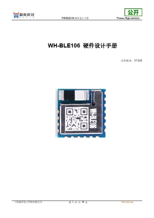
1.2.产品外观图片1实物图1.3.参考文档列表除此硬件开发文档外,我们同时提供了基于本产品的说明书、封装库等资料,方便用户设计参考,客户可到官方网站查看下载:WH-BLE106说明书链接:https:///Download/1126.htmlWH-BLE106封装库可按参考WH-BLE103链接:https:///Download/653.html2产品简介2.1.基本参数表格1参数列表分类参数取值无线参数工作频段2402~2480MHz发射功率-19dBm-+8dBm接收灵敏度-96dBm传输距离模块+模块(max)BLE106(内置天线)170m天线选项内置板载天线、外接引脚焊盘(需要定制生产)硬件参数数据接口UART:1200~1Mbps工作电压 1.7V~3.6V工作电流发射电流(max)22mA@3V3接收电流(max)15mA@3V3休眠电流(avg)0.7u A@3V3工作温度-40℃~+85℃存储温度-40℃~+85℃工作湿度5~95%RH(无凝露)存储湿度5~95%RH(无凝露)尺寸尺寸:10mm x10mm x2.2mm 封装接口SMT表贴2.2.模块应用框图目前模块开放的接口包括:电源、串口、固件下载接口和部分IO口等,如下图所示。
TMCM-1021 硬件手册说明书

MODULE FOR STEPPER MOTORSTRINAMIC Motion Control GmbH & Co. KGHamburg, GermanyHardware Version V1.2HARDWARE MANUAL+ +TMCM-1021++U NIQUE F EATURES :Table of Contents1Features (3)2Order Codes (5)3Mechanical and Electrical Interfacing (6)3.1Size of Board (6)3.2Connectors (7)3.2.1Power, Communication and I/O Connector (8)3.2.2Motor Connector (8)3.3Power Supply (9)3.4Communication (10)3.4.1RS485 (10)3.5Inputs and Outputs (11)3.5.1Digital Inputs IN_0, IN_1, IN_2, IN_3 (11)3.5.2Outputs OUT_0, OUT_1 (12)4Reset to Factory Defaults (13)5On-board LED (13)6Operational Ratings (14)7Functional Description (15)8Life Support Policy (16)9Revision History (17)9.1Document Revision (17)9.2Hardware Revision (17)10References (17)1FeaturesThe TMCM-1021 is a single axis controller/driver module for 2-phase bipolar stepper motors with state of the art feature set. It is highly integrated, offers a convenient handling and can be used in many decentralized applications. The module can be mounted on the back of NEMA11 (28mm flange size) and has been designed for coil currents up to 0.7A RMS and 24V DC supply voltage. With its high energy efficiency from TRINAMIC’s coolStep™ technology cost for power consumption is kept down. The TMCL™ firmware allows for both, standalone operation and direct mode.M AIN C HARACTERISTICSHighlights-Motion profile calculation in real-time-On the fly alteration of motor parameters (e.g. position, velocity, acceleration)-High performance microcontroller for overall system control and serial communication protocol handling-For position movement applications, where larger motors do not fit and higher torques are not requiredBipolar stepper motor driver-Up to 256 microsteps per full step-High-efficient operation, low power dissipation-Dynamic current control-Integrated protection-stallGuard2 feature for stall detection-coolStep feature for reduced power consumption and heat dissipationEncoder-sensOstep magnetic encoder (max. 1024 increments per rotation) e.g. for step-loss detection under all operating conditions and positioning supervisionInterfaces-Up to 4 multi-purpose inputs (2 shared with outputs)- 2 general purpose outputs-RS485 2-wire communication interfaceSoftware-TMCL: s tandalone operation or remote controlled operation,program memory (non volatile) for up to 876 TMCL commands, andPC-based application development software TMCL-IDE available for free.Electrical and mechanical data-Supply voltage: +24V DC nominal (9… 28V DC)-Motor current: up to 0.7A RMS (programmable)Refer to separate TMCL Firmware Manual, too.TRINAMIC S U NIQUE F EATURES – E ASY TO U SE WITH TMCLstallGuard2™ stallGuard2 is a high-precision sensorless load measurement using the back EMF on thecoils. It can be used for stall detection as well as other uses at loads below those which stall the motor. The stallGuard2 measurement value changes linearly over a wide range of load, velocity, and current settings. At maximum motor load, the value goes to zero or near to zero. This is the most energy-efficient point of operation for the motor.Load [Nm]stallGuard2Initial stallGuard2 (SG) value: 100%Max. loadstallGuard2 (SG) value: 0Maximum load reached. Motor close to stall. Motor stallsFigure 1.1 stallGuard2 load measurement SG as a function of loadcoolStep ™coolStep is a load-adaptive automatic current scaling based on the load measurement via stallGuard2 adapting the required current to the load. Energy consumption can be reduced by as much as 75%. coolStep allows substantial energy savings, especially for motors which see varying loads or operate at a high duty cycle. Because a stepper motor application needs to work with a torque reserve of 30% to 50%, even a constant-load application allows significant energy savings because coolStep automatically enables torque reserve when required. Reducing power consumption keeps the system cooler, increases motor life, and allows reducing cost.00,10,20,30,40,50,60,70,80,9050100150200250300350EfficiencyVelocity [RPM]Efficiency with coolStepEfficiency with 50% torque reserveFigure 1.2 Energy efficiency example with coolStep2Order CodesTable 2.2 Order codesA cable loom set is available for this module:Table 2.5 Cable loom order code3Mechanical and Electrical Interfacing3.1Size of BoardThe board with the controller/driver electronics has an overall size of 28mm x 28mm in order to fit on the back side of a NEMA11 (28mm flange size) stepper motor. The printed circuit board outline is marked green in the following figure:PCB outlineR 2.5mmFigure 3.1 Board dimensions and position of mounting holes3.2ConnectorsThe TMCM-1021 has two connectors, an 8-pin power and input/output connector and a 4-pin motor connector (used to connect the attached motor).Power / Communication / IOs11MotorFigure 3.2 TMCM-1021 connectorsOverview of connector and mating connector types:Table 3.2 Connectors and mating connectors, contacts and applicable wire3.2.1Power, Communication and I/O ConnectorAn 8-pin CVIlux CI0108P1VK0-LF 2mm pitch single row connector is used for power supply, RS485 serial communication and additional multi-purpose inputs and outputs.Table 3.3 Power, communication and I/O connector3.2.2Motor ConnectorAn 4-pin CVIlux CI0104P1VK0-LF 2mm pitch single row connector is used for connecting the four motor wires to the electronics.Table 3.4 Motor connector3.3 Power SupplyFor proper operation care has to be taken with regard to power supply concept and design. Due to space restrictions the TMCM-1021 includes just about 20µF/35V of supply filter capacitors. These are ceramic capacitors which have been selected for high reliability and long life time. The module includes a 28V suppressor diode for over-voltage protection.C AUTION !Add external power supply capacitors!It is recommended to connect an electrolytic capacitor of significant size (e.g. 470µF/35V) to the power supply lines next to the TMCM-1021!Rule of thumb for size of electrolytic capacitor: In addition to power stabilization (buffer) and filtering this added capacitor will also reduce any power supply wires and the ceramic capacitors. In addition it will limit slew-rate of power supply stability problems with some switching power supplies.Do not connect or disconnect motor during operation!Motor disconnected / connected while energized. These voltage spikes might exceed voltage limits of power supply before connecting / disconnecting the motor.Keep the power supply voltage below the upper limit of 28V!Otherwise operating voltage is near the upper limit a regulated power supply is highly recommended. Please see also chapter 6, operating values.There is no reverse polarity protection!The transistors.TMCM-1021 V1.2 Hardware Manual (Rev. 1.02 / 2013-JUL-23)10 3.4Communication3.4.1RS485For remote control and communication with a host system the TMCM-1021 provides a two wire RS485 bus interface. For proper operation the following items should be taken into account when setting up an RS485 network:1.BUS STRUCTURE:The network topology should follow a bus structure as closely as possible. That is, the connection between each node and the bus itself should be as short as possible. Basically, it should be short compared to the length of the bus.termination resistor (120 Ohm)termination resistor (120 Ohm)Figure 3.5: Bus structure2.BUS TERMINATION:Especially for longer busses and/or multiple nodes connected to the bus and/or high communication speeds, the bus should be properly terminated at both ends. The TMCM-1021 does not integrate any termination resistor. Therefore, 120 Ohm termination resistors at both ends of the bus have to be added externally.3.NUMBER OF NODES:The RS485 electrical interface standard (EIA-485) allows up to 32 nodes to be connected to a single bus. The bus transceiver used on the TMCM-1021 units (SN65HVD3082ED) has just 1/8th of the standard bus load and allows a maximum of 256 units to be connected to a single RS485 bus.4.NO FLOATING BUS LINES:Avoid floating bus lines while neither the host/master nor one of the slaves along the bus line is transmitting data (all bus nodes switched to receive mode). Floating bus lines may lead to communication errors. In order to ensure valid signals on the bus it is recommended to use a resistor network connecting both bus lines to well defined logic levels. In contrast to the termination resistors this network is normally required just once per bus. Certain RS485 interface converters available for PCs already include these additional resistors (e.g. USB-2-485).terminationresistor(120 Ohm)RS485- / RS485BRS485+ / RS485AFigure 3.6 Bus lines with resistor network3.5 Inputs and Outputs3.5.1 Digital Inputs IN_0, IN_1, IN_2, IN_3The eight pin connector of the TMCM-1021 provides four general purpose inputs IN_0, IN_1, IN_2 and IN_3. The first two inputs have dedicated connector pins while the other two share pins with two general purpose outputs.All four inputs are protected using voltage resistor dividers together with limiting diodes against voltages below 0V (GND) and above +3.3V DC (see figure below).IN_0IN_1IN_2IN_3microcontroller and TMC262Figure 3.7 General purpose inputsThe four inputs have alternate functionality depending on configuration in software. The following functions are available:Table 3.5 Multipurpose inputs / alternate functionsAll four inputs are connected to the on-board processor and can be used as general purpose digital inputs.Using the alternate functionality of IN_0 and IN_1 it is possible to control the on-board stepper motor driver with the help of an external stepper motor controller using step and direction signals. For the step and direction signals the signal levels are the same as for the general purpose digital inputs.IN_3 can be used as analog input, also. A 12bit analog to digital converter integrated in the microcontroller will convert any analog input voltage between 0 and +6.6V to a digital value between 0 and 4095 then.3.5.2Outputs OUT_0, OUT_1The eight pin connector of the TMCM-1021 provides two general purpose outputs. These two outputs are open-drain outputs and can sink up to 100mA each. The outputs of the N-channel MOSFET transistors are connected to freewheeling diodes each for protection against voltage spikes especially from inductive loads (relais etc.).Both outputs OUT_0 and OUT_1 share pins with two of the four inputs (IN_2 resp. IN_3).Please take into account the 20k (2x 10k in series) resistance to ground (transistor not active) of the input voltage divider (figure 4.8) when designing the external “load” circuit.OUT_0 / IN_2OUT_1 / IN_3microcontrollerFigure 3.8 General purpose outputs4Reset to Factory DefaultsIt is possible to reset the TMCM-1021 to factory default settings without establishing a communication link. This might be helpful in case communication parameters of the preferred interface have been set to unknown values or got accidentally lost.For this procedure two pads on the bottom side of the board have to be shortened (see Figure 4.1).Please perform the following steps:1.Power supply off and USB cable disconnected2.Short two pads as marked in Figure 4.13.Power up board (power via USB is sufficient for this purpose)4.Wait until the on-board red and green LEDs start flashing fast (this might take a while)5.Power-off board (disconnect USB cable)6.Remove short between pads7.After switching on power-supply / connecting USB cable all permanent settings have been restoredto factory defaultsShort these two padsFigure 4.1 Reset to factory default settings5On-board LEDThe board offers one LED in order to indicate board status. The function of the LED is dependent on the firmware version. With standard TMCL firmware the green LED flashes slowly during operation.When there is no valid firmware programmed into the board or during firmware update the green LED is permanently on.Green LEDFigure 5.1 On-board LED6Operational RatingsThe operational ratings show the intended or the characteristic ranges and should be used as design values. In no case shall the maximum values be exceeded!Table 6.1 General operational ratings of module*) maximum setting for prototype and first versions of TMCL firmware. Will be adapted in firmware for series version.Table 6.2 Operational ratings of multi-purpose I/OsTable 6.3 Operational ratings of RS485 interface7Functional DescriptionThe TMCM-1021 is a highly integrated controller/driver module which can be controlled via RS485 interface. Communication traffic is kept low since all time critical operations (e.g. ramp calculations) are performed on board. The nominal supply voltage of the unit is 24V DC. The module is designed for both, standalone operation and direct mode. Full remote control of device with feedback is possible. The firmware of the module can be updated via the serial interface.In Figure 7.1 the main parts of the module are shown:-the microprocessor, which runs the TMCL operating system (connected to TMCL memory),-the power driver with its energy efficient coolStep feature,-the MOSFET driver stage, and-the sensOstep encoder with resolutions of 10bit (1024 steps) per revolution.9…Figure 7.1 Main parts of TMCM-1021The TMCM-1021 comes with the PC based software development environment TMCL-IDE for the Trinamic Motion Control Language (TMCL). Using predefined TMCL high level commands like move to position a rapid and fast development of motion control applications is guaranteed. Please refer to the TMCM-1021 Firmware Manual for more information about TMCL commands.8Life Support PolicyTRINAMIC Motion Control GmbH & Co. KG does not authorize or warrant any of its products for use in life support systems, without the specific written consent of TRINAMIC Motion Control GmbH & Co. KG.Life support systems are equipment intended to support or sustain life, and whose failure to perform, when properly used in accordance with instructions provided, can be reasonably expected to result in personal injury or death. © TRINAMIC Motion Control GmbH & Co. KG 2013Information given in this data sheet is believed to be accurate and reliable. However neither responsibility is assumed for the consequences of its use nor for any infringement of patents or other rights of third parties, which may result from its use.Specifications are subject to change without notice.All trademarks used are property of their respective owners.9Revision History9.1Document RevisionFigure 9.1 Document revision9.2Hardware RevisionFigure 9.2 Hardware revision10References[TMCM-1021] TMCM-1021 TMCL Firmware Manual [QSH2818-32-07-006] NEMA11 / 28mm bipolar stepper motor [QSH2818-51-07-012] NEMA11 / 28mm bipolar stepper motor [USB-2-485] USB-2-485 interface converter TRINAMIC manuals are available on .。
硬件设计需求说明书(完整版)
实用文档文档名称文档范围硬件需求说明书内部公开文档编号共12 页DD301硬件需求说明书拟制焦少波日期2016-12-01评审人日期批准日期免费共享修订记录日期修订版本描述作者2016-12-01 1.0.0初稿完成焦少波目录硬件需求说明书 (1)1引言 (6)1.1文档目的 (6)1.2参考资料 (6)2概述 (7)2.1产品描述 (7)2.2产品系统组成 (7)2.2.1XXX 分系统 (7)2.2.2XXX 分系统 (7)2.3产品研制要求 (7)3硬件需求分析 (7)3.1硬件组成 (7)3.1.1XXX 分系统 (8)3.1.2XXX 分系统 (8)3.2系统硬件布局 (8)3.2.1XXX 设备布局 (8)3.2.2XXX 设备布局 (8)3.3系统主要硬件组合 (8)3.4XXX 硬件模块需求 (8)3.4.1功能需求 (9)3.4.2性能需求 (9)3.4.3接口需求 (9)3.4.4RAMS 需求 (9)3.4.5安全需求 (9)3.4.6机械设计需求 (9)3.4.7应用环境需求 (9)3.4.8设计约束 (10)3.5XXX 硬件模块需求 (10)3.5.1功能需求 (10)3.5.2性能需求 (10)3.5.3接口需求 (10)3.5.4RAMS 需求 (10)3.5.5安全需求 (10)3.5.6机械设计需求 (10)3.5.7应用环境需求 (11)3.5.8设计约束 (11)3.6可生产性需求 (11)3.7可测试性需求 (11)3.8外购硬件设备 (11)3.8.1外购硬件 (11)3.8.2仪器设备 (12)3.9技术合作 (12)3.9.1内部合作 (12)3.9.2外部合作 (12)表目录表1 外购硬件清单 (11)表2 仪器设备清单 (12)图目录图1XXX 系统构成框图 (7)图2XXX 系统硬件构成框图 (7)硬件需求说明书关键词:能够体现文档描述内容主要方面的词汇。
Dell PowerEdge R210系统硬件用户手册说明书

Dell™ PowerEdge™ R210 系统 硬件用户手册关于系统使用系统设置程序和 UEFI 引导管理器 安装系统组件 系统故障排除 运行系统诊断程序 跳线和连接器 获得帮助 词汇表注、小心和警告本说明文件中的信息如有更改,恕不另行通知。
© 2009 Dell Inc. 版权所有,翻印必究。
未经 Dell Inc. 书面许可,严禁以任何形式复制这些材料。
文本中使用的商标:Dell 、DELL 徽标和 PowerEdge 是 Dell Inc. 的商标;Microsoft 、Windows 、Windows Server 和 MS-DOS 是 Microsoft Corporation 在美国和/或其它国家/地区的商标或注册商标。
本说明文件中述及的其它商标和产品名称是指拥有相应商标和产品名称的公司或其制造的产品。
Dell Inc. 对本公司的商标和产品名称之外的其它商标和产品名称不拥有任何专有权。
2009 年 8 月 Rev. A00注: "注"表示可以帮助您更好地使用计算机的重要信息。
小心: "小心"表示如果不遵循说明,就有可能损坏硬件或导致数据丢失。
警告: "警告"表示可能会造成财产损失、人身伤害甚至死亡。
项指示灯、按钮或连图标说明1 链路指示灯2 活动指示灯警报信息系统管理软件可以为系统生成警报信息。
警报信息包括针对驱动器、温度、风扇和电源状况的信息、状态、警告和故障信息。
有关详情,请参阅系统管理软件说明文件。
可能需要的其它信息l 机架解决方案附带的机架说明文件介绍了如何将系统安装到机架中。
l 《使用入门指南》概述了系统功能、系统设置以及技术规格。
l系统随附的任何介质,它提供了用于配置和管理系统的说明文件和工具,包括与操作系统、系统管理软件、系统更新以及随系统购买的系统组件相关的说明文件和工具。
返回目录页面警告: 请参阅系统附带的安全与管制信息。
MCU 5310简明使用手册
MCU 5310中文简明使用手册第1章 MCU使用手册1.1 登录方法1、打开浏览器,在地址栏输入MCU地址,按回车确认。
如下图所示:2、点击“登录”,输入用户名和密码,按回车确认,进入MCU主页面输入用户名和密码1.2 MCU功能简介MCU功能包括状态查看、网络设置、系统设置、会议管理、用户管理、终端管理。
主功能栏1.2.1 状态提供MCU的详细信息、会议召开情况和系统运行情况1.2.2 网络进行MCU网络方面的设置,目前只使用网络端口A1.2.3 设置包括会议设置、网守设置、SIP设置和流媒体设置等九大项设置,在后面会详细介绍常用的设置。
设置分项1.2.4 会议包括会议管理、自动应答向导管理和转移与会成员三大项,包括会议发起、操作、结束等功能将在后面进行详细介绍。
会议控制分项1.2.5 用户对MCU的登录账号进行添加、修改等管理选择用户权限1.2.6 终端在MCU上添加、修改终端等管理,相当于添加、修改MCU的号码簿添加终端参数1.3 “设置”功能介绍(只介绍常用部分)1.3.1 会议设置相当于设置会议模板。
1.3.2 本地化设置对用户界面进行设置。
选择会议默认带宽当视频终端加入会议时看到的分屏为发言会场加边框提示选择图像质量不选择以免影响会议效果选择永不显示以免影响会议效果可根据会议要求设置选择经常方便与会者识别会场选择可将标清画质提升选择自动轮询时间间隔一般不要超过70当视音频不同步时才需调整可根据管理员习惯设置1.4 “会议”功能介绍(只介绍常用部分)1.4.1 会议管理1)会议列表对正在召开的会议和已结束对会议进行管理。
点击进入正在召开的会议,对会议进行操作管理;点击进入已结束的会议,修改会议开始时间,让会议再召开而不用重新修改会议设置和选择与会者。
点击在线会议进入会议管理界面。
2)与会成员对当前会议与会成员进行广播、静音、挂断等管理。
3)设置修改当前会议的各项指标。
修改完需点击更新会议才生效4)自定义分屏对当前会议进行指定分屏操作。
M5310EVB手册V1.0
M5310EVB用户使用指南NB-IoT系列版本:V1.0日期:2017-04-05中移物联网有限公司关于文档修改记录目录关于文档 (1)目录 ................................................... - 2 - 1 引言 ................................................ - 3 -1.1.安全须知 (3)2 产品综述 ............................................ - 4 -2.1 评估板的顶视图 (4)2.2 评估板配件视图 (5)3 使用说明 ............................................ - 5 -3.1 电源 (5)3.2 模组使用 (6)3.3 关机 (8)3.4 紧急复位 (8)1 引言为了帮助您更好的开发中移物联网NB-IOT和GSM系列模块的应用程序,中移物联网有限公司特提供此评估板(EVB)供你来测试我们的M5310、M631X模块。
本文可以帮助您快速的了解EVB接口规范,电气和机械的细节以及如何使用它。
1.1. 安全须知通过遵循以下安全原则,可确保个人安全并有助于保护产品和工作环境免遭潜在损坏。
登机前请关闭移动终端设备。
移动终端的无线功能在飞机上禁止开启用以防止对飞机通讯系统的干扰。
忽略该提示项可能会导致飞行安全,甚至触犯法律。
当在医院或健康看护场所,注意是否有移动终端设备使用限制。
RF干扰会导致医疗设备运行失常,因此可能需要关闭移动终端设备。
移动终端设备并不保障任何情况下都能进行有效连接,例如在移动终端设备没有话费或SIM无效。
当你在紧急情况下遇见以上情况,请记住使用紧急呼叫,同时保证您的设备开机并且处于信号强度足够的区域。
您的移动终端设备在开机时会接收和发射射频信号。
当靠近电视,收音机电脑或者其他电子设备时都会产生射频干扰。
PanelView 5310 终端 用户手册说明书
目录
概述 安装 PanelView 5310 终端
配置终端设置
前言
变更摘要. . . . . . . . . . . . . . . . . . . . . . . . . . . . . . . . . . . . . . . . . . . . . . . . . 7 包装清单. . . . . . . . . . . . . . . . . . . . . . . . . . . . . . . . . . . . . . . . . . . . . . . . . 7 索取开源软件包的对应源代码 . . . . . . . . . . . . . . . . . . . . . . . . . . . . . . 8 产品固件和发行说明 . . . . . . . . . . . . . . . . . . . . . . . . . . . . . . . . . . . . . . 8 其他资源. . . . . . . . . . . . . . . . . . . . . . . . . . . . . . . . . . . . . . . . . . . . . . . . . 9
第1章
关于 PanelView 5310 终端 . . . . . . . . . . . . . . . . . . . . . . . . . . . . . . . . 11 硬件特性. . . . . . . . . . . . . . . . . . . . . . . . . . . . . . . . . . . . . . . . . . . . . . . . 12 操作员控制. . . . . . . . . . . . . . . . . . . . . . . . . . . . . . . . . . . . . . . . . . . . . . 13 触摸手势. . . . . . . . . . . . . . . . . . . . . . . . . . . . . . . . . . . . . . . . . . . . . . . . 13 Studio 5000 环境 . . . . . . . . . . . . . . . . . . . . . . . . . . . . . . . . . . . . . . . . 14 EtherNet/IP 通信 . . . . . . . . . . . . . . . . . . . . . . . . . . . . . . . . . . . . . . . . 15 典型配置. . . . . . . . . . . . . . . . . . . . . . . . . . . . . . . . . . . . . . . . . . . . . . . . 15 产品目录号说明 . . . . . . . . . . . . . . . . . . . . . . . . . . . . . . . . . . . . . . . . . 15 产品选择. . . . . . . . . . . . . . . . . . . . . . . . . . . . . . . . . . . . . . . . . . . . . . . . 16 附件. . . . . . . . . . . . . . . . . . . . . . . . . . . . . . . . . . . . . . . . . . . . . . . . . . . . 16 以太网电缆. . . . . . . . . . . . . . . . . . . . . . . . . . . . . . . . . . . . . . . . . . . . . . 17
中移物联 ML305 硬件设计手册说明书
1.14G L TE系列版本:V1.0.1日期:2020年10月服务与支持如果您有任何关于模组产品及产品手册的评论、疑问、想法,或者任何无法从本手册中找到答案的疑问,请通过以下方式联系我们。
OneMO官网:邮箱:*****************************.com客户服务热线:400-110-0866微信公众号:CMOneMO文档声明注意本手册描述的产品及其附件特性和功能,取决于当地网络设计或网络性能,同时也取决于用户预先安装的各种软件。
由于当地网络运营商、ISP,或当地网络设置等原因,可能也会造成本手册中描述的全部或部分产品及其附件特性和功能未包含在您的购买或使用范围之内。
责任限制除非合同另有约定,中移物联网有限公司对本文档内容不做任何明示或暗示的声明或保证,并且不对特定目的适销性及适用性或者任何间接的、特殊的或连带的损失承担任何责任。
在适用法律允许的范围内,在任何情况下,中移物联网有限公司均不对用户因使用本手册内容和本手册中描述的产品而引起的任何特殊的、间接的、附带的或后果性的损坏、利润损失、数据丢失、声誉和预期的节省而负责。
因使用本手册中所述的产品而引起的中移物联网有限公司对用户的最大赔偿(除在涉及⼈身伤害的情况中根据适⽤法律规定的损害赔偿外),不应超过用户为购买此产品而支付的金额。
由于产品版本升级或其他原因,本文档内容会不定期进行更新。
除非另有约定,本文档仅作为使用指导,本文档中的所有陈述、信息和建议不构成任何明示或暗示的担保。
公司保留随时修改本手册中任何信息的权利,无需进行提前通知且不承担任何责任。
商标声明为中国移动注册商标。
本手册和本手册描述的产品中出现的其他商标、产品名称、服务名称和公司名称,均为其各自所有者的财产。
进出口法规出口、转口或进口本手册中描述的产品(包括但不限于产品软件和技术数据),用户应遵守相关进出口法律和法规。
隐私保护关于我们如何保护用户的个人信息等隐私情况,请查看相关隐私政策。
Inspiron 13 5310 设置和规格说明书
Inspiron 13 5310设置和规格8 2021注意、小心和警告:“注意”表示帮助您更好地使用该产品的重要信息。
:“小心”表示可能会损坏硬件或导致数据丢失,并告诉您如何避免此类问题。
:“警告”表示可能会导致财产损失、人身伤害甚至死亡。
© 2021 Dell Inc. 或其子公司。
保留所有权利。
Dell、EMC 和其他商标是 Dell Inc. 或其附属机构的商标。
其他商标可能是其各自所有者的商标。
章 1: 设置 Inspiron 13 5310 (4)章 2: Inspiron 13 5310的视图 (6)右 (6)左侧 (6)顶部 (7)正面 (8)底部 (9)章 3: Inspiron 13 5310 的规格 (10)尺寸和重量 (10)处理器 (10)芯片组 (11)操作系统 (11)内存 (11)外部端口 (12)内部插槽 (12)无线模块 (12)音频 (13)存储 (13)英特尔傲腾内存 H10 和固态存储(可选) (14)键盘 (14)摄像头 (15)触控板 (15)电源适配器 (15)电池 (16)显示屏 (17)指纹读取器(可选) (17)GPU —集成 (18)GPU —独立 (18)操作和存储环境 (18)章 4: 戴尔低蓝光显示屏 (19)章 5: Inspiron 13 5310 的键盘快捷方式 (20)章 6: 获取帮助和联系戴尔 (22)目录3设置 Inspiron 13 5310:根据您所订购的配置,本文档中的图像可能与您的计算机有所差异。
1.连接电源适配器,然后按下电源按钮。
: 在运输过程中,电池可能会进入节能模式,以节省电池电量。
首次开机时,确保电源适配器已连接到计算机。
2.完成 Windows 设置。
按照屏幕上的说明完成设置。
设置时,戴尔建议您执行以下操作:●Windows 更新。
: 如果您正在连接到加密的无线网络,请在出现系统提示时输入访问无线网络所需的密码。
联想V130–20IGM AIO用户指南和硬件维护手册说明书
图 5. 连接 Kensington 式钢缆锁
© Copyright Lenovo 2018
9
10 V130–20IGM AIO 用户指南和硬件维护手册
第 4 章 更换硬件
本章提供如何为您的计算机更换硬件的说明。
更换硬件之前
注意:打开计算机或尝试进行任何修理之前,请先阅读本节和《重要产品信息指南》。
第 2 章 规格
电源 • 65 瓦电源适配器
存储驱动器 • 2.5 英寸存储驱动器 • M.2 存储驱动器(选配)
视频功能部件 集成显卡支持以下各项: • HDMI 输出接口
音频功能部件 集成声卡支持以下各项: • 耳麦接口
输入/输出(I/O)功能部件 • 音频接口(耳机) • 读卡器插槽 • 显示器接口(HDMI 输出) • 以太网接口 • USB 接口
扩展 • 读卡器插槽 • M.2 存储驱动器插槽(选配) • 内存插槽 • 光盘驱动器(选配) • 存储驱动器托架
网络功能 • 以太网 LAN • 无线局域网 • 蓝牙