毕设外文翻译电子版

7.1 INTRODUCTION
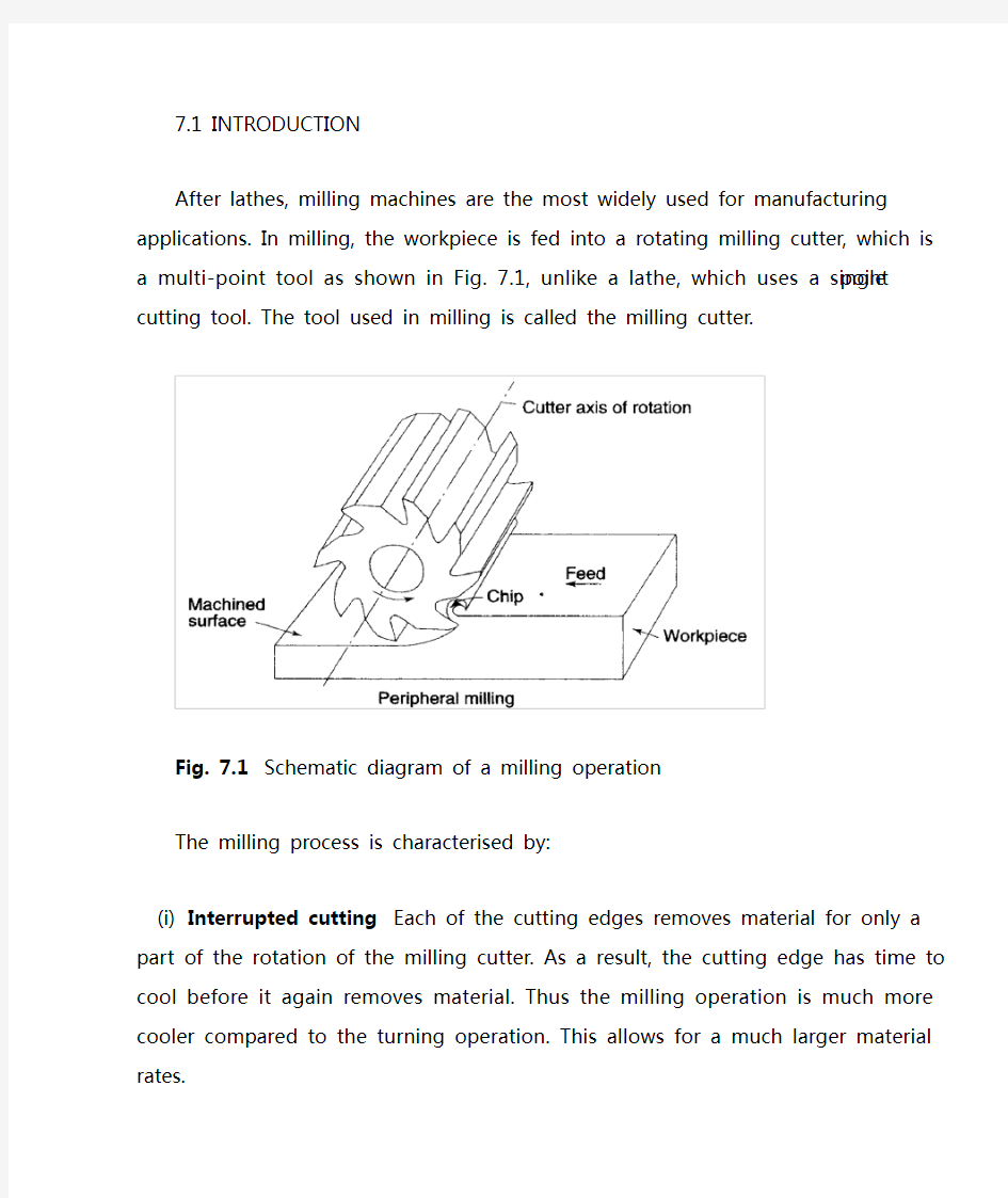
After lathes, milling machines are the most widely used for manufacturing applications. In milling, the workpiece is fed into a rotating milling cutter, which is a multi-point tool as shown in Fig. 7.1, unlike a lathe, which uses a single point cutting tool. The tool used in milling is called the milling cutter.
Fig. 7.1Schematic diagram of a milling operation
The milling process is characterised by:
(i)Interrupted cutting Each of the cutting edges removes material
for only a part of the rotation of the milling cutter. As a result, the cutting edge has time to cool before it again removes material.
Thus the milling operation is much more cooler compared to the turning operation. This allows for a much larger material rates.
(ii)Small size of chips Though the size of the chips is small, in view of the multiple cutting edges in contact a large amount of material is removed and as a result the component is generally completed in
a single pass unlike the turning process which requires a large
number of cuts for finishing.
(iii)Variation in chip thickness This contributes to the non-steady state cyclic conditions of varying cutting forces during the contact of the cutting edge with the chip thickness varying from zero to maximum size or vice versa. This cyclic variation of the force can excite any of the natural frequencies of the machine tool system and is harmful to the tool life and surface finish generated
A milling machine is one of the most versatile machine tools. It is adaptable for quantity production as well as in job shops and tool rooms. The versatility of milling is because of the large variety of accessories and tools available with milling machines. The typical tolerance expected from the process is about ±0.050 mm.
7.2 TYPES OF MILLING MACHINES
To satisfy various requirements milling machines come in a number of sizes and varieties. In view of the large material removal rates
milling machines come with a very rigid spindle and large power. The varieties of milling machines available are:
(i) Knee and Column type
(a) horizontal
(b) vertical
(c) universal
(d) turret type
These are the general purpose milling machines, which have a high degree of flexibility and are employed for all types of works including batch manufacturing. A large variety of attachments to improve the flexibility are available for this class of milling machines.
(ii) Production (Bed) type
(a) simplex
(b) duplex
(c) triplex
These machines are generally meant for regular production involving large batch sizes. The flexibility is relatively less in these machines which is suitable for productivity enhancement.
(iii) Plano millers
These machines are used only for very large workpieces involving table travels in meters.
(iv) Special type
(a) Rotary table
(b) Drum type
(c) Copy milling (Die sinking machines)
(d) Key way milling machines
(e) Spline shaft milling machines
These machines provide special facilities to suit specific applications that are not catered to by the other classes of milling machines.
7.2.1 Knee and Column Milling Machines
The knee(升降台) and column type is the most commonly used machine in view of its flexibility and easier setup. A typical machine construction is shown in Fig. 7.2 for the horizontal axis. The knee houses the feed mechanism and mounts the saddle and table. The table basically has the T-slots running along the X-axis for the purpose of work holding. The table moves along the X-axis on the saddle while the saddle moves along the Y-axis on the guide ways provided on the knee.
The feed is provided either manually with a hand wheel or connected for automatic by the lead screw, which in turn is coupled to the main spindle drive. The knee can move up and down (Z-axis) on a dovetail provided on the column.
Fig. 7.2 Horizontal knee and column type milling machine
The massive column at the back of the machine houses all the power train including the motor and the spindle gearbox. The power for feeding the table lead screw is taken from the main motor through a separate feed gearbox. Sometimes a separate feed motor is provided for the feed gearbox as well.
While the longitudinal and traverse motions are provided with automatic motion, the raising of the knee is generally made manually.
The spindle is located at the top end of the column. The arbour used to mount the milling cutters is mounted in the spindle and is provided with a support on the other end to take care of the heavy cutting forces by means of an overarm with bearing. As shown in Fig.
7.2 the overarm extends from the column with a rigid design. The spindle nose has the standard Morse taper of the suitable size
depending upon the machine size.
The milling cutters are mounted on the arbour at any desired position, the rest of the length being filled by standard hardened collars of varying widths to fix the position of the cutter. The arbour is clamped in the spindle with the help of a draw bar and then fixed with nuts.
Milling machines are generally specified on the following basis:
(i) Size of the table, which specifies the actual working area on the table and relates to the maximum size of the workpiece that can be accommodated.
(ii) Amount of table travel, which gives the maximum axis movement that is possible.
(iii) Horse power of the spindle, which actually specifies the power of the spindle motor used. Smaller machines may come with 1 to 3 hp while the production machines may go from 10 to 50 hp.
Another type of knee and column milling machine is the vertical axis type. Its construction is very similar to the horizontal axis type, except for the spindle type and location.
The vertical axis milling machine is relatively more flexible (Fig. 7.4) and suitable for machining complex cavities such as die cavities in tool rooms. The vertical head is provided with a swiveling facility in horizontal direction whereby the cutter axis can be swivelled. This is
useful for tool rooms where more complex milling operations are carried out.
The spindle is located in the vertical direction and is suitable for using the shank mounted milling cutters such as end mills, In view of the location of the tool, the setting up of the workpiece and observing the machining operation is more convenient.
Fig, 7.3 Vertical knee and column type milling machine
Fig.7.4 Some of the milling operations normally carried out on vertical axis machines
The universal machine has the table which can be swivelled in a horizontal plane at about 45o to either the left or right. This makes the universal machine suitable for milling spur and helical gears as well as worm gears and cams.
7.2.2 Bed Type Milling Machine
In production milling machines it is desirable to increase the metal removal rates. If it is done on conventional machines by increasing
the depth of cut, there is possibility of chatter. Hence another variety
of milling machines named as bed type machines are used which are made more rugged and are capable of removing more material. The ruggedness is obtained as a consequence of the reduction in versatility.
The table in the case of bed type machines is directly mounted on the bed and is provided with only longitudinal motion.
The spindle moves along with the column to provide the cutting action. Simplex machines (Fig. 7.5) are the ones with only one spindle head while duplex machines have two spindles (Fig. 7.6). The two spindles are located on either side of a heavy workpiece and remove material from both sides simultaneously.
Fig. 7.5 Simplex bed type milling machine
Fig. 7.6 Duplex bed type milling machine
7.3 MILLING CUTTERS
There are a large variety of milling cutters available to suit specific requirements. The versatility of the milling machine is contributed to
a great extent by the variety of milling cutters that are available.
7.3.1 Types of Milling Cutters
Milling cutters are classified into various types based on a variety of methods.
(i) Based on construction:
(a) Solid
(b) Inserted tooth type
Based on mounting:
(a) Arbor mounted
(b) Shank mounted
(c) Nose mounted
Base on rotation:
(a) Right hand rotation (counter clockwise)
(b) Left hand rotation (clockwise)
Based on helix:
(a) Right hand helix
(b) Left hand helix
Milling cutters are generally made of high speed steel or cemented carbides. The cemented carbide cutters can be of a brazed tip variety or with indexable tips. The indexable variety is more common since it is normally less expensive to replace the worn out cutting edges than to regrind them.
Plain milling cutters These are also called slab milling cutters and are basically cylindrical with the cutting teeth on the periphery as shown in Fig. 7.7. These are generally used for machining flat surfaces.
Fig. 7.7 Arbor mounted milling cutters for general purpose
Light duty slab milling cutters generally have a face width, which is small of the order of 25 mm. They generally have straight teeth and large number of teeth.
Heavy duty slab milling cutters come with a smaller number of teeth to allow for more chip space. This allows taking deeper cuts and consequently high material removal rates.
Helical milling cutters have a very small number of teeth but a large helix angle. This type of cutter cuts with a shearing action, which can produce a very fine finish. The large helix angle allows the cutter to absorb most of the end load and therefore the cutter enters and leaves the workpiece very smoothly.
Side and face milling cutters These have the cutting edges not only on
the face like the slab milling cutters, but also on both the sides. As a
result, these cutters become more versatile since they can be used for side milling as well as for slot milling.
Staggered tooth side milling cutters are a variation where the teeth are arranged in an alternate helix pattern. This type is generally used for milling deep slots, since the staggering of teeth provides for greater chip space.
Another variation of the side and face cutter is the half side milling cutter, which has cutting edges only on one side. This arrangement provides a positive rake angle and is useful for machining on only one side. These have a much smoother cutting action and a long tool life. The power consumed is also less for these cutters.
Fig. 7.8Special forms of arbor mounted milling cutters
Slitting saws The other common form of milling cutters in the arbor mounted category is the slitting saw. This is very similar to a saw blade in
appearance as well as function. Most of these have teeth around the circumference while some have side teeth as well. The thickness of these cutters is generally very small and is used for cutting off operations or for deep slots.
Special form cutters In addition to the general type of milling cutters described above, there are a large number of special form milling cutters available which are used for machining specific profiles.
Angular milling cutters are made in single or double angle cutters for milling any angle such as 30, 45 or 60o Form relieved cutters are made of various shapes such as circular, corner rounding, convex or concave shapes.
T-slot milling cutters are used for milling T-slots such as those in the milling machine table. The central slot is to be milled first using an end mill before using the T-slot milling cutter. Woodruff key seat milling cutters are used for milling as the name suggests, woodruff key seats Some other special form cutters are dovetail milling cutters and gear milling cutters.
End mills These are shank mounted as shown in Fig. 7.9 and are generally used in vertical axis milling machines. They are used for milling slots, key ways and pockets where other type of milling cutters cannot be used. A depth of cut of almost half the diameter can be taken with the end mills.
The end mills have the cutting edge running through the length of the cutting portion as well as on the face radially up to a certain length. The helix angle of the cutting edge promotes smooth and efficient cutting even at high cutting speeds and feed rates. High cutting speeds(转速?) are generally recommended for this type of milling cutters.
Fig. 7.9 Shank mounted milling cutters and various types of end mills There are a large variety of end mills. One of the distinctions is based on the method of holding, i.e., the end mill shank can be straight or tapered. The straight shank is used on end mills of small size and held in the milling machine spindle with the help of a suitable collet. The tapered shank can be directly mounted in the spindle with the help of the self
holding taper. If the taper is small compared to the spindle taper, then an adopter accommodating both the tapers is used.
The end teeth of the end mills may be terminated at a distance from the cutter center or may proceed till the center (Fig. 7.9 f). Those with the cutting edge up to the center are called slot drills or end cutting end mills since they have the ability to cut into the solid material (Fig. 7.9 g). The other type of end mills which have a larger number of teeth cannot cut into solid material and hence require a pilot hole drilled before a pocket is machined.
The cutting edge along the side of an end mill is generally straight and sometimes can be tapered by grinding on a tool and cutter grinder such that the draft required for mould and die cavities can be automatically generated.
毕设外文资料翻译.
理工学院 毕业设计外文资料翻译 专业:计算机科学与技术 姓名:马艳丽 学号: 12L0752218 外文出处:The Design and Implementation of 3D Electronic Map of Campus Based on WEBGIS 附件: 1.外文资料翻译译文;2.外文原文。
附件1:外文资料翻译译文 基于WebGIS的校园三维电子地图的设计与实现 一.导言 如今,数字化和信息化是当今时代的主题。随着信息革命和计算机科学的发展,计算机技术已经渗透到科学的各个领域,并引起了许多革命性的变化,在这些科目,古代制图学也不例外。随着技术和文化的不断进步,地图变化的形式和内容也随之更新。在计算机图形学中,地理信息系统(GIS)不断应用到Web,制作和演示的传统方式经历了巨大的变化,由于先进的信息技术的发展,地图的应用已经大大延长。在这些情况下,绘图将面临广阔的发展前景。电子地图是随之应运而生的产品之一。随着计算机技术,计算机图形学理论,遥感技术,航空摄影测量技术和其他相关技术的飞速发展。用户需要的三维可视化,动态的交互性和展示自己的各种地理相关的数据处理和分析,如此多的关注应支付的研究三维地图。东北石油大学及其周边地区的基础上本文设计并建立三维电子地图。 二.系统设计 基于WebGIS的校园三维电子地图系统的具有普通地图的一般特性。通过按键盘上的箭头键(上,下,左,右),可以使地图向相应的方向移动。通过拖动鼠标,可以查看感兴趣的任何一个地方。使用鼠标滚轮,可以控制地图的大小,根据用户的需求来查看不同缩放级别的地图。在地图的左下角会显示当前鼠标的坐标。在一个div层,我们描绘了一个新建筑物的热点,这层可以根据不同的地图图层的显示,它也可以自动调整。通过点击热点,它可以显示热点的具体信息。也可以输入到查询的信息,根据自己的需要,并得到一些相关的信息。此外,通过点击鼠标,人们可以选择检查的三维地图和卫星地图。 主要功能包括: ?用户信息管理:检查用户名和密码,根据权限设置级别的认证,允许不同权限的用户通过互联网登录系统。 ?位置信息查询:系统可以为用户提供模糊查询和快速定位。
翻译译文
应用程序基础Android Developers Android应用程序使用Java编程语言开发。aapt工具把编译后的Java代码连同应用程序所需的其他数据和资源文件一起打包到一个Android包文件中,这个文件使用.apk作为扩展名。此文件是分发并安装应用程序到移动设备的载体;是用户下载到他们的设备的文件。单一.apk文件中的所有代码被认为是一个应用程序。 从多个角度来看,每个Android应用程序都存在于它自己的世界之中: 1 默认情况下,每个应用程序均运行于它自己的Linux进程中。当应用程序中的任何代码需要被执行时,Android启动此进程,而当不再需要此进程并且其它应用程序又请求系统资源时,则关闭这个进程。 每个进程都有其独有的虚拟机(VM),所以应用程序代码与所有其它应用程序代码是隔离运行的。 3 默认情况下,每个应用程序均被赋予一个唯一的Linux用户ID,并加以权限设置,使得应用程序的文件仅对此用户及此应用程序可见——尽管也有其它的方法使得这些文件同样能为其他应用程序所访问。 1 应用程序组件 Android的一个核心特性就是一个应用程序可以使用其它应用程序的元素(如果那个应用程序允许的话)。例如,如果你的应用程序需要显示一个图片卷动列表,而另一个应用程序已经开发了一个合用的而又允许别的应用程序使用的话,你可以直接调用那个卷动列表来完成工作,而不用自己再开发一个。你的应用程序并没有吸纳或链接其它应用程序的代码。它只是在有需求的时候启动了其它应用程序的那个功能部分。 为达到这个目的,系统必须能够在一个应用程序的任何一部分被需要时启动一个此应用程序的进程,并将那个部分的Java对象实例化。因此,不像其它大多数系统上的应用程序,Android应用程序并没有为应用程序提供一个单独的入口点(比如说,没有main()函数),而是为系统提供了可以实例化和运行所需的必备组件。一共有四种组件类型: 1 Activity activity是为用户操作而展示的可视化用户界面。例如,一个activity可以展示一个菜单项列表供用户选择,戒者显示一些包含说明文字的照片。一个短消息应用程序可以包括一个用于显示要发送消息到的联系人列表的activity,一个给选定的联系人写短信的activity以及翻阅以前的短信或改变设置的其他activity。
1外文文献翻译原文及译文汇总
华北电力大学科技学院 毕业设计(论文)附件 外文文献翻译 学号:121912020115姓名:彭钰钊 所在系别:动力工程系专业班级:测控技术与仪器12K1指导教师:李冰 原文标题:Infrared Remote Control System Abstract 2016 年 4 月 19 日
红外遥控系统 摘要 红外数据通信技术是目前在世界范围内被广泛使用的一种无线连接技术,被众多的硬件和软件平台所支持。红外收发器产品具有成本低,小型化,传输速率快,点对点安全传输,不受电磁干扰等特点,可以实现信息在不同产品之间快速、方便、安全地交换与传送,在短距离无线传输方面拥有十分明显的优势。红外遥控收发系统的设计在具有很高的实用价值,目前红外收发器产品在可携式产品中的应用潜力很大。全世界约有1亿5千万台设备采用红外技术,在电子产品和工业设备、医疗设备等领域广泛使用。绝大多数笔记本电脑和手机都配置红外收发器接口。随着红外数据传输技术更加成熟、成本下降,红外收发器在短距离通讯领域必将得到更广泛的应用。 本系统的设计目的是用红外线作为传输媒质来传输用户的操作信息并由接收电路解调出原始信号,主要用到编码芯片和解码芯片对信号进行调制与解调,其中编码芯片用的是台湾生产的PT2262,解码芯片是PT2272。主要工作原理是:利用编码键盘可以为PT2262提供的输入信息,PT2262对输入的信息进行编码并加载到38KHZ的载波上并调制红外发射二极管并辐射到空间,然后再由接收系统接收到发射的信号并解调出原始信息,由PT2272对原信号进行解码以驱动相应的电路完成用户的操作要求。 关键字:红外线;编码;解码;LM386;红外收发器。 1 绪论
外文翻译 - 英文
The smart grid Smart grid is the grid intelligent (electric power), also known as the "grid" 2.0, it is based on the integration, high-speed bidirectional communication network, on the basis of through the use of advanced sensor and measuring technology, advanced equipme nt technology, the advanced control method, and the application of advanced technology of decision support system, realize the power grid reliability, security, economic, efficient, environmental friendly and use the security target, its main features include self-healing, incentives and include user, against attacks, provide meet user requirements of power quality in the 21st century, allow all sorts of different power generation in the form of access, start the electric power market and asset optimizatio n run efficiently. The U.S. department of energy (doe) "the Grid of 2030" : a fully automated power transmission network, able to monitor and control each user and power Grid nodes, guarantee from power plants to end users among all the nodes in the whole process of transmission and distribution of information and energy bi-directional flow. China iot alliance between colleges: smart grid is made up of many parts, can be divided into:intelligent substation, intelligent power distribution network, intelli gent watt-hourmeter,intelligent interactive terminals, intelligent scheduling, smart appliances, intelligent building electricity, smart city power grid, smart power generation system, the new type of energy storage system.Now a part of it to do a simple i ntroduction. European technology BBS: an integration of all users connected to the power grid all the behavior of the power transmission network, to provide sustained and effective economic and security of power. Chinese academy of sciences, institute of electrical: smart grid is including all kinds of power generation equipment, power transmission and distribution network, power equipment and storage equipment, on the basis of the physical power grid will be modern advanced sensor measurement technology, network technology, communication
外文翻译-基于Android智能家居系统
通信工程学院 毕业设计外文翻译 毕业设计题目基于ANDRIO的智能家居 系统的设计与实现 外文题目UBIQUITOUS SMART HOME SYSTEM USING ANDROID APPLICATION 专业:通信工程 学号: 学生姓名: 指导教师姓名: 指导教师职称:副教授 日期:2015 年 1 月10 日
International Journal of Computer Networks & Communications (IJCNC) V ol.6, No.1, January 2014 基于Android应用的无处不在的智能家居系统 Shiu Kumar Department of Information Electronics Engineering, Mokpo National University, 534-729, Mokpo, South Korea 摘要 本文提出了一种灵活独立的,低成本的智能家居系统,它是基于Android应用与微web服务器通信,不仅仅提供交换功能。Arduino以太网的使用是为了避免使用个人电脑从而保证整个系统成本最低,语音激活时用来实现切换功能的。光开关,电源插头,温度传感器,湿度传感器,电流传感器,入侵检测传感器,烟雾/气体传感器和警报器等这些设备集成在系统中,表明了所提出的智能家居系统的有效性和可行性。经过检测,智能家居应用程序可以成功地进行智能家居操作,例如开关功能,自动环境监测,和入侵监测,在监测到有不法入侵后,系统会自动发送一个邮件,并响警笛。 关键字: Android智能手机,智能家居,物联网(loTs),远程控制 1.引言 随着移动设备受欢迎程度的不断增长和人们日常生活中对无处不在的先进的移动应用的功能需求不断增加,利用Web服务是提供远程访问服务的最开放和可互操作的方式,并且使应用程序能够彼此通信。一个有吸引力的市场产品自动化和网络化是忙碌的家庭和有生理缺陷的个人的代表。 loTs可以被描述为连接智能手机,网络电视,传感器等到互联网,实现人们之间沟通的新形势。过去几年中loTs的发展,创造了一个新层面的世界。这使得人们可以在任何时间,任何地点,联通任何期望的东西。物联网技术可用于为智能家居创建新的概念和广阔的空间,以提供智能,舒适的发展空间和完善生活质量。 智能家居是一个非常有前途的领域,其中有各种好处,如增加提供舒适性,更高安全性,更合理地使用能源和其他资源。这项研究的应用领域非常重要,未来它为帮助和支持有特殊需求老的人和残疾人士提供了强有力的手段。设计一个智能家居系统时需要考虑许多因素,该系统应该是经济实惠的,是可伸缩的,使得新的设备可以容易地集成到系统中,此外,它应该是用户友好的。 随着智能手机用户的急剧增加,智能手机已经逐渐变成了具备所有功能的便携式设备,为人们提供了日常使用。本文介绍了一种低成本的控制和监视家居环境控制的无线智能家居系统。利用Android设备,可以通过一个嵌入式微Web服务器与实际的IP连接,访问和控制电器和远程的其它设备,这可以利用任何支持Android的设备。Arduino Ethernet 用于微Web服务器从
外文翻译1
译文(一) THE ACCOUNTING REVIEW V ol. 83, No. 3 2008 pp. 823–853 市场参与者的杜邦分析的使用 马克?t?Soliman 华盛顿大学 文摘:杜邦分析,一种常见的财务报表分析,依靠于净营业资产收益率的两个乘法组件:利润率和资产周转率。这两个会计比率衡量不同的构造。因此,有不同的属性。之前的研究已经发现,资产周转率的变化是未来收益的变化正相关。本文全面探讨了杜邦组件和沿着三个维度有助于文学。首先,本文有助于财务报表分析文献,发现在这个会计信息信号实际上是增量学习会计信号在先前的研究在预测未来收益。其次,它有助于文学在股票市场上使用的会计信息通过检查眼前和未来的股本回报投资者应对这些组件。最后,它增加了分析师的文献处理会计信息的再次测试直接和延迟反应的分析师通过同期预测修正以及未来预测错误。一致的跨市场加入者的两组,结果表明是有用的信息就是明证杜邦组件和股票收益之间的联系以及维度分析师预测。然而,我发现预测未来预测错误和异常返回信息处理表明似乎没有完成。平均水平,分析表明杜邦组件代表增量和可行的操作特征信息的公司。 关键词:财务报表分析、杜邦分析、市场回报、分析师预估。 数据可用性:在这项研究中使用的数据是公开的来源显示的文本。 在本文中,我分析杜邦分析中包含的信息是否与股市回报相关和分析师预测。之前的研究文档组件从杜邦分析,分解的净营业资产收益率为利润率和资产周转率,有解释力对未来盈利能力的变化。本文增加了文献综合研究投资者和分析师反应杜邦组件三个维度。首先,它复制先前记录的预测能力和检查是否健壮和增量其他预测已经考虑在文学的存在。其次,它探讨了使用这些组件的股市投资者通过观察同生和未来收益。在同时代的长窗协会和短时期限信息测试,结果显示积极联系杜邦组件和股本回报率。但小未来异常返回交易策略显示的信息可能不完整的处理。最后,检查当前预测修正由卖方分析师和未来的预测错误。尽管他们似乎修改他们的预测未来收益与这些杜邦组件中的信息一致,修订似乎不完整就是明证可预测的未来预测错误。一致的市场参与者,在两组同期结果表明,信息是有用的,但是未来的测试表明,信息处理似乎没有完成。 由金矿和笔者(2001)提供了一个使用剩余收益的股票估值方法框架,给出了一个简单的财务比率分析的直接映射到股票估值。特别是他们用杜邦分析,分解公司的净营业资产收益率(RNOA)利润率(PM)和资产周转率(ATO)点的地方1。PM和ATO会计信号,测量不同结构对一个公司的业务2。PM 往往是来自定价权,如产品创新,产品定位,品牌知名度,先发优势和市场定位。ATO措施资产利用率和效率,通常来自于有效的利用财产,工厂和设备,有效的库存流程;和其他形式的资本管理工作3。 我们有理由期待竞争力量的影响这两个来源盈利能力不同。大的利润率通常吸引新进入者进入市场或快速模仿新思想从现有的竞争对手。由此产生的竞争导致高利润率回归正常水平,暗示更多暂时的利益。与利润不同,然而,竞争可能少威胁要部署一个有效的资产。更难以模仿另一个公司的高效生产流程因为这样模仿通常包括大型和昂贵的改革目前的工厂和操作。 1.具体来说,RNOA营业收入/平均净营业资产,PM营业收入/销售和ATO销售 /平均净营业资产。此后,点和ATO被称为“杜邦公司组成”。另一个常见的形式是分解罗伊(利润杠杆资产周转率)或(NI /产品销售/资产资产/股本)。讨论的“估值理论和RNOA”部分,我在分析使用RNOA为了专注于操作,因此抽象从公司的融资决策。 2.例如,阿伯克龙比和惠誉赚取高额利润通过出售used-looking服装被认为是时髦和青少年所要
毕业设计外文翻译
毕业设计(论文) 外文翻译 题目西安市水源工程中的 水电站设计 专业水利水电工程 班级 学生 指导教师 2016年
研究钢弧形闸门的动态稳定性 牛志国 河海大学水利水电工程学院,中国南京,邮编210098 nzg_197901@https://www.360docs.net/doc/5618041783.html,,niuzhiguo@https://www.360docs.net/doc/5618041783.html, 李同春 河海大学水利水电工程学院,中国南京,邮编210098 ltchhu@https://www.360docs.net/doc/5618041783.html, 摘要 由于钢弧形闸门的结构特征和弹力,调查对参数共振的弧形闸门的臂一直是研究领域的热点话题弧形弧形闸门的动力稳定性。在这个论文中,简化空间框架作为分析模型,根据弹性体薄壁结构的扰动方程和梁单元模型和薄壁结构的梁单元模型,动态不稳定区域的弧形闸门可以通过有限元的方法,应用有限元的方法计算动态不稳定性的主要区域的弧形弧形闸门工作。此外,结合物理和数值模型,对识别新方法的参数共振钢弧形闸门提出了调查,本文不仅是重要的改进弧形闸门的参数振动的计算方法,但也为进一步研究弧形弧形闸门结构的动态稳定性打下了坚实的基础。 简介 低举升力,没有门槽,好流型,和操作方便等优点,使钢弧形闸门已经广泛应用于水工建筑物。弧形闸门的结构特点是液压完全作用于弧形闸门,通过门叶和主大梁,所以弧形闸门臂是主要的组件确保弧形闸门安全操作。如果周期性轴向载荷作用于手臂,手臂的不稳定是在一定条件下可能发生。调查指出:在弧形闸门的20次事故中,除了极特殊的破坏情况下,弧形闸门的破坏的原因是弧形闸门臂的不稳定;此外,明显的动态作用下发生破坏。例如:张山闸,位于中国的江苏省,包括36个弧形闸门。当一个弧形闸门打开放水时,门被破坏了,而其他弧形闸门则关闭,受到静态静水压力仍然是一样的,很明显,一个动态的加载是造成的弧形闸门破坏一个主要因素。因此弧形闸门臂的动态不稳定是造成弧形闸门(特别是低水头的弧形闸门)破坏的主要原是毫无疑问。
APP开发合同范本(标准版).docx
编号:_________________ APP开发合同范本 甲方:________________________________________________ 乙方:________________________________________________ 签订日期:_________年______月______日
甲方:________________________________(以下简称甲方) 地址:_______________________________________________ 法定代表人:_____________联系电话:_______________ 乙方:(以下简称乙方) 地址:_______________________________________________ 法定代表人:联系电话: 甲、乙双方经友好协议,就甲方委托乙方开发《____________________________________》(以下简称"本软件")的事宜达成一致并同意订本合同。 一、项目内容 1. 甲方委托乙方开发的软件《_XX系统APP,安卓系统APP,网络平台__》(以下简称"本三个软件") 在安卓,XX,PC环境下运行的软件,本三个软件需求(以下简称"需求")双方协商确定。
2.本合同APP和网络平台应用开发的栏目架构及相关功能开发细节由《APP和网络平台开发需求表》载明。 二、合同价款和付款方式 1.本合同总价款包括乙方相关的税费及软件开发期间办理相关手续的所有费用。该价款为固定包干价,除上述款项外,甲方无需支付任何其它款项。 2.付款方式: 前期不要源码的甲方总支付乙方费用是27500元,预付定金为10000元,软件和平台做好交付可以使用付清前期不要源码的费用的余额17500(留3000元质保金),即14500元 后期甲方要回乙方源码,乙方要另加收甲方27500元费用,并付清3000元的质保金 三、开发进度 自合同签订日起,甲方把钥匙交给乙方匹配乙方将在_____30_______个工作日内完成客户端开发,此时间并包括审核和测试时间。乙方的工作时间从本合同签订之日的次日起开始计算。
5外文翻译原文1
A Case Study of Pattern-based Software Framework to Improve the Quality of Software Development Chih-Hung Chang, Chih-Wei Lu Dept. of Information Management, Hsiuping Institute of Technology No.11, Gongye Rd., Dali City, Taichung County, Taiwan(R.O.C.) 886-4-24961123 ext 3112 {chchang,cwlu}@ https://www.360docs.net/doc/5618041783.html,.tw William C. Chu Dept. of Computer Science and Information Engineering, Tunghai University No.181, Sec. 3, Taichung Port Rd.,Taichung City, Taiwan (R.O.C.) 886-4-23508983 cchu@https://www.360docs.net/doc/5618041783.html,.tw Nien-Lin Hsueh Dept. of Information Engineering and Computer Science, Feng Chia University No. 100 Wenhwa Rd., Taichung, Taiwan (R.O.C.) 886-4- 24517250 ext 3773 nlhsueh@https://www.360docs.net/doc/5618041783.html,.tw Chorng-Shiuh Koong Dept. of Computer and Information Science, Taichung University No.140, Ming-Sheng Rd., Taichung City, Taiwan (R.O.C.) 886-4-22183804 csko@https://www.360docs.net/doc/5618041783.html,.tw ABSTRACT In recent years, development of the software industry and demand for software systems have increased rapidly, but developers often does not know whose suggestion to follow regarding methodologies of software engineering. One reason for that is the difficulty in applying new software engineering technologies. Developers take a long time to train. Another reason is the difficulty in integrating CASE toolsets. So many indeterminate factors make the development process more and more complex. On the other hand, software development is too customized, and software reuse is difficult. T he reasons above are the cause for software development and maintenance to become more complex and difficult to control. In this paper we explore the importation of a software pattern-based framework, and the development of an ERP/support chain system. Based on software patterns, developers can separate development and business so as to reduce problems caused by the developer’s lack of business experience. T he quality of the product can thus be enhanced, software development costs be reduced, and software maintenance be improved. Keywords Design Pattern, Framework, Software Development Process, XML 1.INTRODUCTION In Object-Oriented T echnology, the property of inheritance allows software components to be reused, which can obviously reduce the cost of software development. For this reason, to produce a highly reusable software component is an important goal of software engineering. However, programmers are usually focused on code reuse while ignoring design reuse. Design patterns provide a clear concept of design structure by describing the relationships of inheritance and reference between components of the system. Design patterns are a series of familiar usages and constructions utilized throughout system design. Design patterns allow rapid coding of certain components by following certain patterns of steps. T his can improve the documentation and maintenance of existing systems by providing an explicit specification of class, object interactions and their underlying intents. One of the main purposes of design patterns is to help software engineers to understand the common characteristics of software objects/components in specialized domain. In recent years, due to the development and maturation of WWW and Java [14] technologies, many applications are now web applications or leaning in that direction. Many software concepts are utilized for the web as well, such as Design Patterns and Frameworks. The Apache Struts [12] and Spring Framework [13] are both open source frameworks used to address and reduce the complexity of developing an enterprise application. T he advantage of using a framework is the layered architecture it provides. Layered architecture allowed users to choose the component desired, while also providing the integration framework when developing application using J2EE. T hese developing web concepts can facilitate the development of web applications. However, these very useful tools and concepts lack a systematic organization. We hope to use these open source software technologies to develop a software framework which can be applied to web application. T his should solve the problem of web applications lacking a good structure, while through applying these open source software technologies, software development costs will be reduced. Furthermore, a guideline for programmers who wants to use these open source technologies will be provided. This paper is organized as follows: In the next section, we discuss works related to our project; in section 3, the open source technologies used in the paper and the system implementation will be described; Section 4 is a sample experiment. T he conclusion is given in section 5.
毕设外文文献翻译
xxxxxxxxx 毕业设计(论文)外文文献翻译 (本科学生用) 题目:Poduct Line Engineering: The State of the Practice 生产线工程:实践的形态 学生姓名:学号: 学部(系): 专业年级: 指导教师:职称或学位: 2011年3月10日
外文文献翻译(译成中文1000字左右): 【主要阅读文献不少于5篇,译文后附注文献信息,包括:作者、书名(或论文题目)、出版社(或刊物名称)、出版时间(或刊号)、页码。提供所译外文资料附件(印刷类含封面、封底、目录、翻译部分的复印件等,网站类的请附网址及原文】 Requirements engineering practices A precise requirements engineering process— a main driver for successful software development —is even more important for product line engineering. Usually, the product line’s scope addresses various domains simultaneously. This makes requirements engineering more complex. Furthermore, SPL development involves more tasks than single-product development. Many product line requirements are complex, interlinked, and divided into common and product-specific requirements. So, several requirements engineering practices are important specifically in SPL development: ? Domain identification and modeling, as well as commonalities and variations across product instances Separate specification and verification for platform and product requirements ? Management of integrating future requirements into the platform and products ? Identification, modeling, and management of requirement dependencies The first two practices are specific to SPL engineering. The latter two are common to software development but have much higher importance for SPLs. Issues with performing these additional activities can severely affect the product line’s long-term success. During the investigation, we found that most organizations today apply organizational and procedural measures to master these challenges. The applicability of more formal requirements engineering techniques and tools appeared rather limited, partly because such techniques are not yet designed to cope with product line evelopment’s inherent complexities. The investigation determined that the following three SPL requirements engineering practices were most important to SPL success. Domain analysis and domain description. Before starting SPL development, organizations should perform a thorough domain analysis. A well-understood domain is a prerequisite for defining a suitable scope for the product line. It’s the foundation for efficiently identifying and distinguishing platform and product requirements. Among the five participants in our investigation, three explicitly modeled the product line requirements. The others used experienced architects and domain experts to develop the SPL core assets without extensive requirements elicitation. Two organizations from the first group established a continuous requirements management that maintained links between product line and product instance requirements. The three other organizations managed their core assets’ evolution using change management procedures and versioning concepts. Their business did not force them to maintain more detailed links between the requirements on core assets and product instances. The impact of architectural decisions on requirements negotiations. A stable but flexible architecture is important for SPL development. However, focusing SPL evolution too much on architectural issues will lead to shallow or even incorrect specifications. It can cause core assets to ignore important SPL requirements so that the core assets lose relevance for SPL development. Organizations can avoid this problem by establishing clear responsibilities for requirements management in addition to architectural roles. The work group participants reported that a suitable organizational tool for balancing requirements and architecture is roundtable meetings in which requirements engineers,
基于Android的智能家居APP的设计与实现_过程检查记录表 -
南京邮电大学通达学院毕业设计(论文)过程检查记录 题目基于Android的智能家居APP的设计与实现 学生姓名班级学号专业计算机科学与技术指导教师姓名指导教师职称副教授日期指导记录 16.1.8-16.1.23 任务计划: 1. 了解课题,查找相关资料 2. 检索中文数据库 完成情况: 1. 首先,通过阅读李涛的《基于Android的智能家居APP的设计与实现》对于这个题目有了一个整体的了解。 2. 然后利用CNKI检索了城市交通与Android相关的学术期刊。下载与课题相关的期刊、论文,阅读资料并理解课题。 指导教师批阅意见: 指导教师签字: 16.1.24-16.2.8 任务计划: 1. 阅读《疯狂Android讲义》对安卓UI设计的技术做一定的了解 2. 了解智能家居App的发展趋势和前景。 完成情况: 1. 通过相关理论学习,初步掌握安卓UI设计。 2. 通过资料了解了智能家居APP的前景。 指导教师批阅意见: 指导教师签字: 16.2.9-16.2.24 任务计划: 1.理清自己题目的思路。 2.完成开题报告 完成情况: 1.在之前理论知识的积累上,对课题任务有了进一步的了解,完成开题报告初稿。 指导教师批阅意见: 指导教师签字: 16.2.25-16.3.4 任务计划: 1.提交开题报告 2.利用CNKI检索与课题相关的外文资料
完成情况: 1.经过老师的指导,不断修改,完成开题报告最终稿,经过审核,打印提交给老师。 2.搜索数据库,查找符合要求的外文资料。 指导教师批阅意见: 指导教师签字: 16.3.5-16.3.20 任务计划: 1.对外文资料开始进行翻译 2.查找Android开发的相关书籍 完成情况: 1.本周开始对外文资料进行翻译,外文资料专业性很强,下手有些困难,但是,仍继续尽全力去做。 2.阅读了《第一行代码》、《疯狂Android讲义》等入门级书籍,对于安卓开发整体有了较完整的理解。 指导教师批阅意见: 指导教师签字: 16.3.21-16.3.31 任务计划: 1.完成APP的需求分析。 2.进行界面设计。 完成情况: 1.将毕业设计的要求进行分析理解,并通过研究其他同类APP明白自己APP所要实现的功能。 2.根据现在世面上的智能家居应用,进行模仿并根据需求完成UI设计。 指导教师批阅意见: 指导教师签字: 16.4.1-16.4.11 任务计划: 1. 进行管理员模块的功能设计。 2. 编写管理员模块。 完成情况: 1. 根据需求分析,进行功能的分割,确定管理员模块的功能。 2. 根据的管理员模块的功能,进行代码编写,完成管理员模块的功能。 指导教师批阅意见: 指导教师签字: 16.4.12-16.4.22 任务计划: 1. 进行用户端的功能设计。 2. 编写用户端的实现功能代码。