ADAMS实例建模仿真
ADAMS实例建模仿真

ADAMS实例建模仿真Adams 实例建模仿真⽬录Adams课程论⽂ (1)第⼀章模型的建⽴ (2)1、模型的介绍 (2)2、启动ADAMS (2)3、栅格设置 (3)4、创建齿轮 (3)5、创建连杆 (5)6、创建滑块 (6)第⼆章创建转动副,移动副,齿轮副,驱动⼒,仿真 (7)1、创建转动副 (7)2、创建移动副 (8)3、创建齿轮副 (9)4、创建驱动⼒ (10)5、仿真 (11)第三章计算结果后处理 (12)1、滑块的速度曲线 (12)2、滑块位移曲线 (12)3、滑块加速度曲线 (13)4、齿轮1与齿轮2转⾓曲线 (13)5、连杆曲线图 (14)6、录制动画并导出 (15)第四章总结 (17)第⼀章模型的建⽴1、模型的介绍如图⼀所⽰,该模型由齿数z为200,模数m为4,半径400mm的齿轮1,齿数z为100,模数m为4,半径200mm的齿轮2,以及连杆和滑块组成。
该模型的运动形式为齿轮1为驱动轮,带动齿轮2转动,齿轮2于连杆偏⼼连接,带动连杆推动滑块直线反复运动。
实质上是将齿轮的转动转化为滑块的平动。
图1-1 模型简图2、启动ADAMS2.1 在桌⾯点击ADAMS快捷键Adams - View x64 2013,或者Windows开始菜单启动:“开始”—“所有程序”—“MSC.Software”—“Adams x64 2013”—“A View”—“Adams-View”。
2.2 启动后出现Welcome欢迎窗⼝,如图1-1所⽰,点击New Model,出现Create New Model,Model Name为adams,Gravity为Earth Normal,Units为MMKS。
2.3 单击OK,进⼊ADAMS。
图1-2 启动ADAMS3、栅格设置3.1 点击Setting,选择Working Grid。
3.2 弹出的窗⼝设置⽹格范围尺⼨,如图1-2所⽰。
图1-3 修改栅格4、创建齿轮4.1 如图1-3所⽰,单击Bodies菜单栏中的圆柱体(Cylinder),在出现的对话框中设置圆柱的长度(Length)50mm和半径(Radius)400mm。
ADAMS平板式抓取机构建模与仿真

ADAMS大作业机构名称:平板式抓取机构指导老师:贾璐学号:姓名:H L班级:机制一班目录1、启动工作环境 (2)1.1启动ADAMS软件 (2)2、设置工作环境 (2)2.1设置工作网格 (2)2.2设置图标 (3)2.3调出坐标 (3)2.4设置单位 (3)3、建模 (3)3.1画出平面闭合曲线 (3)3.1.1平面闭合曲线一的绘制 (3)3.1.2曲线二的绘制 (4)3.1.3曲线三的绘制 (5)3.1.4曲线四的绘制 (5)3.2拉伸成三维实体 (5)3.2.1曲线一的拉伸 (6)3.2.2曲线二的拉伸 (6)3.2.3曲线三的拉伸 (6)3.2.4曲线四的拉伸 (6)3.3孔的绘制 (7)3.4贯通杆的绘制 (8)3.5使贯通杆与Part5形成一个整体 (8)3.6长方体块的绘制与移动 (8)3.6.1绘制 (8)3.6.2移动 (9)3.7连杆的绘制 (10)4、添加各种副 (11)4.1添加转动副 (11)4.2添加固定副 (12)4.3添加移动副 (12)5、添加运动及运动函数的编辑 (13)5.1添加运动 (13)5.2运动函数的编辑 (13)6、防真 (14)7、防真分析 (15)7.1位移曲线一的生成 (15)7.2位移曲线二的生成 (16)7.3角度曲线的生成 (17)8、视频输出 (18)9、退出ADAMS (20)10、感想 (20)1、启动工作环境1.1启动ADAMS软件双击ADAMS图标,命名如图1-1,点击进入ADAMS 工作环境。
右击,点击,将背景颜色修改为白色。
图1-12、设置工作环境2.1设置工作网格点击,选择其中的,将工作网格设置为如图2-1所示,点击完成设置。
图2-12.2设置图标点击,选择其中的,将图标设置为如图2-2所示,点击完成设置。
图2-22.3调出坐标单击网格,F42.4设置单位保持默认单位不变3、建模3.1画出平面闭合曲线3.1.1平面闭合曲线一的绘制右击,再单击,保持默认设置不变,依次单击网格上的(-550,0,0),(-550,150,0),(550,150,0),(550,0,0),(300,0,0),(300,50,0),(-300,50,0),(-300,0,0),最后回到(-550,0,0)点时右击确认。
(完整版)Adams运动仿真例子--起重机的建模和仿真
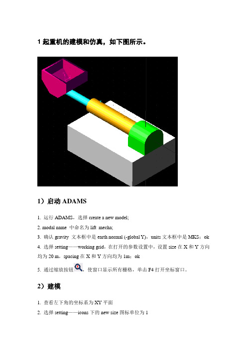
1起重机的建模和仿真,如下图所示。
1)启动ADAMS1. 运行ADAMS,选择create a new model;2. modal name 中命名为lift_mecha;3. 确认gravity 文本框中是earth normal (-global Y),units文本框中是MKS;ok4. 选择setting——working grid,在打开的参数设置中,设置size在X和Y方向均为20 m,spacing在X和Y方向均为1m;ok5. 通过缩放按钮,使窗口显示所有栅格,单击F4打开坐标窗口。
2)建模1. 查看左下角的坐标系为XY平面2. 选择setting——icons下的new size图标单位为13. 在工具图标中,选择实体建模按钮中的box按钮4. 设置实体参数;On groundLength :12Height:4Depth:85. 鼠标点击屏幕上中心坐标处,建立基座部分6. 继续box建立Mount座架部件,设置参数:New partLength :3Height:3Depth: 3.5设置完毕,在基座右上角建立座架Mount部件7. 左键点击立体视角按钮,查看模型,座架Mount不在基座中间,调整座架到基座中间部位:①右键选择主工具箱中的position按钮图标中的move按钮②在打开的参数设置对话框中选择Vector,Distance项中输入3m,实现Mount 移至基座中间位置③设置完毕,选择座架实体,移动方向箭头按Z轴方向,Distance项中输入2.25m,完成座架的移动右键选择座架,在快捷菜单中选择rename,命名为Mount8. 选择setting—working grid 打开栅格设置对话框,在set location中,选择pick 选择Mount.cm座架质心,并选择X轴和Y轴方向,选择完毕,栅格位于座架中心选择主工具箱中的视角按钮,观察视图将spacing—working grid ,设置spacing中X和Y均为0.510. 选择圆柱实体绘图按钮,设置参数:New partLength:10mRadius:1m选择座架的中心点,点击左侧确定轴肩方向,建立轴肩,单击三维视图按钮,观察视图11. 继续圆柱工具,绘制悬臂①设置参数:New partLength: 13mRadius: 0.5m②选择Mount.cm作为创建点,方向同轴肩,建立悬臂③右键选择新建的悬臂,在快捷菜单中选择part_4——Rename,命名为boom④选择悬臂,移动方向沿X轴负向,实现悬臂的向左移动:1)右键选择工具箱中的position按钮中的move按钮2)在打开的参数对话框中,选择vector,distance中输入2m,点击悬臂,实现移动⑤右键点击实体建模按钮,在弹出的下一级菜单中选择导圆角工具,设置圆角半径为1.5m⑥左键选择座架上侧的两条边,点击右键,完成倒角12. 选择box按钮图标,创建铲斗①设置参数:New partLength : 4.5Height: 3.0Depth: 4.0②选择悬臂左侧中心点,命名为bucket,建立铲斗③右键选择position按钮下一级按钮move按钮④在打开的参数对话框中,选择vector,distance中输入2.25m,选择铲斗,移动方向沿全部坐标系X轴负方向,实现铲斗的横向移动⑤在主工具箱中,选择三维视图按钮,察看铲斗⑥继续选择move按钮,设置参数中选择vector,distance中输入2.0m,选择铲斗,移动方向沿全部坐标系 Z轴负方向,实现铲斗的纵向移动⑦移动完毕,选择主工具箱中的渲染按钮render,察看三维实体效果,再次选择render按钮,实体图则以线框显示⑧右键点击实体建模按钮,再弹出的下一级按钮中选择倒角工具,在打开的参数设置对话框中,设置倒角Width为1.5m,⑨选择铲斗下侧的两条边,完毕单击右键,完成倒角⑩右键选择实体建模工具按钮,再下一级按钮中选择Hollow按钮,在打开的参数设置对话框中设置参数Thickness为0.25m选择铲斗为挖空对象,铲斗上平面为工作平面,完毕点击右键挖空铲斗3)添加约束根据图示关系,添加链接①在主工具箱中,选择转动副,下方的参数设置对话框中,设置参数2 bod ——1 loc和pick feature②选择基座和座架,然后选择座架中心Mount.cm,旋转轴沿y轴正向,建立座架与基座的转动副③继续用转动副按钮,建立轴肩与座架间的转动副,设置参数为2 bod——1 loc 和Normal to grid,选择轴肩和座架,再选择座架中心点,建立转动副④继续用转动副按钮,建立铲斗与悬臂间的转动副,设置参数为2 bod——1 loc 和Normal to grid,选择铲斗与悬臂,再选择铲斗下侧中心点,建立转动副⑤选择主工具箱中的平动副,设置参数2 bod——1 loc和pick feature,选择悬臂与轴肩,再选择悬臂中心标记点,移动方向沿X轴正方向,建立悬臂和轴肩间的平动副⑥右键点击窗口右下角的Information 信息按钮,选择约束按钮,观察是否按要求施加约束,关闭信息窗口⑦检查完毕,选择仿真按钮,对系统进行仿真,观察系统在重力作用下的运动4)添加运动①选择主工具箱中的旋转运动按钮,右键点击座架中心标记点,在弹出的选择窗口中,选择JOINT_mount_ground,给座驾与基座的转动副添加转动运动②选择俯视图按钮,观察旋转运动副的箭头图标③右键点击该运动,在弹出的快捷菜单中选择motion_mount_ground——modify在修改对话框中,修改function项为360d*time④重复上述动作,在轴肩和座架之间建立旋转运动Motion_shoulder_ground,⑤右键点击该运动,在弹出的快捷菜单中选择motion_shoulder_ground——modify在修改对话框中,修改function项为-STEP(time,0,0,0.10,30d)⑥重复上述动作,在铲斗和悬臂之间建立旋转运动Motion_bucket_boom⑦设置运动函数为45d*(1-cos(360d*time))⑧右键点击主工具箱中旋转运动按钮,选择下一级平行运动按钮,点击悬臂中心平动副,在悬臂和座架间建立平行运动⑨设置平行运动函数为STEP(time,0.8,0,1,5)⑩选择主工具箱中的仿真按钮,设置仿真参数END Time:1;Steps:100,进行仿真5)测量和后处理①鼠标右键点击铲斗,打开右键快捷键,选择测量measure②系统打开参数设置对话框,将Characteristic设置为CM Point,Component 设置为Y,测量Y向位移。
基于ADAMS的往复式活塞压缩机的建模与仿真

基于ADAMS的往复式活塞压缩机的建模与仿真第1章基于ADAMS的往复式活塞压缩机的建模与仿真本章以往复式活塞压缩机的运动为例,介绍在ADAMS环境中进行模型建模和约束的添加,以及对建立好的模型进行仿真分析。
1.1模型分析该模型由气缸、活塞、连杆、中心动力轴架和齿轮组成,如图1-1所示。
图1-1往复活塞式压缩机模型1.2启动ADAMS并设置工作环境1.2.1启动ADAMS双击桌面上ADAMS/View的快捷图标,打开ADAMS/View。
在欢迎对话框中选择“Create a new model”,在模型名称(Model name)栏中输入:compressor。
在重力名称(Gravity)栏中选择(Earth Normal (-Global Y);在单位名称(Units)栏中选择“MMKS-mm,kg,N,s,deg”。
如图1-2所示。
设置完毕后单击OK按钮,进入ADAMS主页面。
图1-2创建新模型1.2.2设置工作环境(1)对于这个模型,网格间距需要设置的合适以满足要求。
在ADAMS/View菜单栏中,选择设置(Setting)下拉菜单中的工作网格(Working Grid)命令。
系统弹出设置工作网格对话框,将网格的尺寸(Size)中的X和Y分别设置成400mm和400mm,间距(Spacing)中的X和Y都设置成5mm,然后点击OK确定,如图1-3所示。
图1-3设置工作网格对话框图1-4坐标窗口(2)用鼠标左键点击选择(Select)图标,控制面板出现在工具箱中。
用鼠标左键点击动态放大(Dynamic Zoom)图标,在模型窗口中,点击鼠标左键并按住不放,移动鼠标进行放大或缩小。
按键盘上的F4键打开坐标窗口Coordinate Window,如图1-4所示。
1.3齿轮模型的创建及仿真1.3.1创建齿轮模型(1)在主工具箱中右击几何建模按钮(默认的是连杆工具)展开所有的几何建模工具(Rigid Box)。
ADAMS仿真实例

A Report Submitted in Partial Fulfillment of theRequirements for SYDE 461ContentsContents ii Table of Figures iv 1Project Summary 11.1 Problem statement (1)1.2 Phase 1 goals (2)2Design Process 4 3Results Achieved 83.1 PCB modifications (8)3.2 Mechanical issues resolved (9)Limit switches (10)Hip motor encoders (11)3.3 Gait research (12)3.4 ADAMS simulation (13)3.5 Communication testing (15)4Future Plans 175Tentative Schedule 19 Appendix A C3 Meeting Minutes 22 C3 meeting #1 (22)C3 meeting #2 (25)C3 meeting #3 (29)Table of FiguresFigure 1: Black-Box System (4)Figure 2: Detailed System Diagram (5)Figure 3: Limit Switch Placement (10)Figure 4: Hip motor encoder (11)Figure 5: ADAMS model of Hexplorer (14)1Project SummaryHexplorer is an evolutionary project intended to research and develop a small, six-legged, autonomous walking robot. The project encompasses all design areas required to make a robot move, including Printed Circuit Board (PCB) design, mechanical design and walking algorithms. Since its initial conception in 1996, the Hexplorer project has seen much change and several improvements.The present Hexplorer configuration is composed of a circular body with six legs mounted equidistant from each other around the circumference of the body. Each leg has three degrees of freedom and therefore requires three separate DC motors to articulate i ts motion. Each leg has its own “leg” PCB with an integrated DSP that controls the leg‟s three motors. The overall motion of the robot is achieved using a single “brain” board, also with an integrated DSP, responsible for sending commands to each of the individual leg boards.1.1Problem statementAs of September 2002, Hexplorer was incapable of autonomous motion. Only two of the six legs were functional, and furthermore, the legs movements were completely controlled by the leg boards rather than beingdirected by the brain board and actuated by the leg boards. Since improvements had recently been made to many of Hexplorer‟s subsystems including a complete re-design of the legs and the integration of new DSPs on all the circuit boards, it was decided that only minor changes would be needed to be made to get the robot to walk. Thus, the problem facing this year‟s design group was to fix any and all mechanical and software problems with Hexplorer, which would allow the robot to walk.The problem statement for this project is as follows:To better understand the intricacies involved in a locomotion machine, and to experiment with sophisticated GAIT algorithms, the Hexplorer 2002 team will remedy any problems with the existing robot, to allow it to autonomously navigate an even surface.1.2Phase 1 goalsIt was decided to have all mechanical and circuit board issues with the robot resolved by December 2002. This would leave the team to implement and design advanced walking algorithms for the robot during the following term.After careful investigation it was shown that to advance Hexplorer to a level where it could be used as a gait-testing platform would require three major tasks.1.Understand and correct the problems with the PCBs responsible forcontrolling Hexplorer‟s movement.2.Repair any mechanical issues preventing the legs of Hexplorer frommoving – including limit switches and motor encoders.3.Research gait algorithms and create a simulation of Hexplorer toallow for designing and testing of these algorithms without damage to the actual robot.With these detailed goals in mind, the team set out to create a sound research platform that could later be used to develop and test complex and autonomous walking gait algorithms.2Design ProcessSince the principal problem f acing this year‟s Hexplorer team was that the robot would not move; a thorough systems approach was required. The team, having no previous experience with this robot, thought of this problem as a …black box‟. Inputs were fed into the system, but nothing was being returned. With detailed research and analysis, this …black-box‟ was subsequently broken down into smaller, recognizable components. Figure 1 shows the original problem facing the Hexplorer 2002 design team.‘BLACK-BOX’Figure 1: Black-box systemThe first step to recognizing the underlying problems was to separate the problem into smaller, more manageable components. The team worked together with the supervisor to identify the major components limiting the motion of Hexplorer. From information passed on by previous Hexplorer teams, and rigorous testing, the team was able to isolate the system components shown in Figure 2.‘BLACK-BOX’Figure 2: Detailed system diagramUsing Figure 2 as a guide, the main areas for malfunction were identified. The possible problematic areas are circled on the diagram. The team was next able to focus its efforts on investigating the following situations.The first problem with the robot was that seven circuit boards were not all in perfect working order. From the strictly hardware perspective, a board was considered functional if the board was able to 1) download code and 2) run the code. Unfortunately, none of the boards were able to download code. The previous Hexplorer team had labeled some of the circuit boards as either “Working” or “Not Working”, but they did not indicate why the “Not Working” boards were not working. The problem with to downloading code could have been localized in either the circuit board DSPs, the other components on the board, of the method used to download the code. Thesolution strategy for this problem involved isolating the problem area and resolving the issue.The second problem with the robot was that hip encoders were apparently not working. This problem could be attributed to either the shaft not being connected to the encoder, the encoder was not providing a signal to the PCB, or the PCB was not properly interpreting the signal. As with the first problem, the solution strategy involved isolation the problem area and resolving the issue.The third problem involved the four limit switches on each of the legs. Some of the limit switches were missing, and furthermore, not all the limit switches were guaranteed to be operational. Therefore, each limit switch would have to be tested and the missing and faulty limit switches would have to be replaced.The fourth and final identified problem involved the communication between the brain board and the leg boards. Although the foundations for this communication have been implemented in both the leg and brain DSP code, the test programs provided by the previous group did not involve the brain specifying foot locations to each of the legs. The most that the previous group was able to accomplish in terms of this communication was a simple pinging program between the brain and the leg. Therefore, thecommunication code in both the leg and the brain would have to be studied, tested, and modified if necessary, and then a communication scheme would have to be designed and implemented into both the leg and brain test programs.3Results AchievedThrough valuable research and hard work, the team was successfully able to address the predefined term goals. Cooperation of team members throughout the design process was the key to success for this phase of Hexplorer‟s development.3.1PCB modificationsAt present, all seven circuit boards are now downloading code and running code successfully. The first problem with the boards was that the method to download the code was incorrect. As the program code is to be downloaded to the Flash, the Flash Programmer tool should be used to download code. Furthermore, the reset button on the boards had to be depressed while the Flash Programmer tool was downloading code. This information was obtained by contacting the previous group.However, even in using the correct method, the seven boards were still not downloading code correctly. After much testing and research, it was determined that the problem involved the Flash p rogrammer‟s clock frequency. The clock that is used to program the DSP is provided by a small circuit external to the DSP. The Flash programming utility is set to expect a certain frequency. For the downloading of code to work correctly, these twofrequencies should be identical. However, it was found that the two frequencies were quite far apart: the clock frequency on the DSP was 80MHz while the Flash Programmer was expecting 30MHz. To resolve this issue, software parameters in the Flash Programmer were modified so that both the clock frequency on the DSP and the frequency expected by software were both 20MHz.After resolving this issue, six of the seven boards were now functional, but there was still one leg board that did not download code. Considering that the malfunctioning board was identical to the other leg boards in design, it was determined that the problem with the board was component related. Some resistors and capacitors that were known to be problematic were first replaced, but the board still was not functional. Finally, it was decided that the DSP had to be replaced. Once the new DSP was soldered onto the board, the board functioned correctly.3.2Mechanical issues resolvedFixing the minor mechanical problems of Hexplorer involved primarily the selection and purchasing of additional limit switches. However, it was also necessary to check that the encoders for the hip motors were workingproperly. Initially there was some skepticism on the reliability of these devices, but they were proven to be working normally.Limit switchesEach leg of the robot requires four limit switches. Figure 3 shows there is one limit switch for the hip, and one for each leg motor. Although not yet attached, eventually one limit switch must be placed near the robot foot.Figure 3: Limit switch placement When the team began working with Hexplorer in September, numerous limit switches were either broken or missing. Some additional hardware was also required to attach the limit switches to the legs. Using the existing limit switches as a guide, more switches were ordered online from an electronics supplier called DigiKey. Some price comparisons were performed topurchase the required switches at the lowest price.Leg LimitSwitchesHipAlthough a seemingly trivial problem of purchasing components, the team found it a valuable learning experience to purchase these limit switches from a recognized supplier. The team conversed with technical representatives at DigiKey to ensure the proper parts were ordered, and in doing so learned important information about electronic components.Hip motor encodersTo ensure that the hip motors were rotating the appropriate amount, it was decided to check the effectiveness of the hip encoders. Figure 4 shows the placement of the hip encoders, placed below the hip joint.Hip MotorEncoderFigure 4: Hip motor encoderBecause the legs of Hexplorer sporadically did not rotate the desired amount, it was suspected that the hardware responsible for counting the revolutions of the motors was faulty. The team set up a simple test to checkif in fact the encoders were malfunctioning. To do this, one of the legs was run through a typical homing sequence, and the values of the encoders were measured using an oscilloscope. After several tests achieving desired results, it was concluded that there was no problem with the hardware. Any discrepancies must be caused by the software responsible for rotating the legs.The team found this testing exercise a valuable learning experience primarily because it promoted teamwork and cooperation. Both team members were actively involved in these tests and by studying the appropriate data sheets, were able to learn more about the hardware involved in Hexplorer.3.3Gait researchFor this phase of the project, research was conducted on various naturally existing gaits. The most common types of Gaits for six-legged insects are the tri-pod gate and the ripple gate (or wave gait). Many insects in fact use a combination of the depicted gaits, depending on the situation. However, for the purposes of this phase of the project, each gait will be simulated separately, with no advanced combinations.The ripple gate keeps the maximum number of feet in contact with the ground to provide the maximum stability for the robot. In the ripple gait, the rear pair of legs is moved, then the middle pair, and then the front pair. The body is then translated forward, with all feet remaining on the ground. The sequence is then repeated. Unfortunately, because the robot only advances after all six legs have moved, the walking motion is very slow.To improve the speed of the robot, a tri-pod gate can be used. In the tri-pod gait, three legs move at a time: the middle leg on one side and the front and rear legs on the other side. Provided the three legs form a …tri-pod‟ around the centre of mass of the robot, this gait will maintain stability. The tri-pod is much faster than the ripple gait because the body is translated forward each cycle by three legs, while the other three legs get into position.Because of the superior speed and reasonable stability, the team has decided to implement the tri-pod gait as the primary walking algorithm of Hexplorer. To be created next term, this design process will be discussed further in the Future Plans section.3.4ADAMS simulationTo test multiple gait algorithms and to study the torque requirements on each of the motors of Hexplorer, a simulation was created in a software programcalled ADAMS. This tool allows the user to run a simulation of a mechanical system, and subsequently plot reaction forces and torques. ADAMS also allows the user to perform inverse kinematics and dynamics analysis on a particular mechanism.From previous Hexplorer teams, an ADAMS model of one of the legs of Hexplorer was obtained. This model was slightly modified to account for recent changes and then combined to form a complete model of Hexplorer. The resulting model is shown in Figure 5.Figure 5: ADAMS model of HexplorerWith the model created, a few simple movements were tested to examine the behaviour of the robot. The first simulation tested the responsiveness of one individual leg. The model was created with a contact force to groundthat allowed for realistic slipping of the feet. However, this individual leg was capable of translation in one direction only. When all six legs were connected to the base, and subsequently simulated, the robot moved in a realistic manner over the surface of the model.This recreation has given the team a valuable tool for testing and analyzing the gaits that are to be implemented in the second phase of the project. During the construction this model, much was learned about the ADAMS software and its vast capabilities.3.5Communication testingOne of the present components that the Hexplorer group is working on is attempting to exercise the Brain-Leg communication channels. To properly control the walking gait of the robot, the brain must deliver desired foot positions to the legs and the legs must reply when the leg reaches the desired position or if the desired position is unreachable. The current line of testing is trying to test these two communication messages.Once the communications testing is completed, the brain should be able to coordinate some walking gait algorithm. The Hexplorer group should be able to get the robot walking in a simple tri-pod gait by the end of December.This first gait algorithm will not include the control structure or inverse kinematics.4Future PlansOver the next term, the Hexplorer group plans on implementing a simple gait algorithm using a more sophisticated control structure that coordinate the legs to ensure that they are working most efficiently together. This algorithm will be able to monitor and control the speed of up to nine motors using four DSPs (three leg DSPs and the brain DSP) to translate the body with three feet on the ground. Furthermore, in this algorithm, the brain will demand foot position as a coordinate in space instead of using encoder counts. This will involve implementing inverse kinematics equations, which relate position to encoder counts and vice versa, on the leg DSP boards. The implementation of this algorithm is planned to be completed by the end of January 2003.The Hexplorer team then plans on entering the Ontario Engineering Competition in February 2003 with the walking robot in the Corporate Design category. The team has already approached the Canadian Space Agency and MD Robotics to “sponsor” the project. The team is also planning on entering the Texas Instruments DSP competition in the summer.Between these two competitions, the team will attempt to implement more sophisticated gait algorithms than the simple tri-pod gait. In is theteam‟s hope that these advanced walking algorithms will be able to be displayed at the TI DSP competition.5Tentative ScheduleThe following table outlines preliminary goals and deadlines based on rough calculations. Due-dates may be shifted slightly as more information is learned.Appendix AC3 Meeting MinutesC3 meeting #1Location: E2-1303ETime: 10:00 PMNo Regrets!Intelligent Vacuum cleaner group (Jimmy, Keith, Sam) -two approaches-GPS, location of the vacuum-Try to cover the specific area-Activate it and make sure that it covers all areas-Random algorithm or pattern algorithm-Internal sensing system (no external system required) -Battery life is an issue-No pre-programming-Figures the boundary on it‟s own-power assumption-vacuums use lots of power-need own power systemQ/A- How big is it and what is the shape? (0.5 meter by 0.5 meter, square or a car shaped)- What is your power source? (Not sure at this moment)- What is your goal for this term? (Algorithm done)Hexplorer group (Damien and Nick)-six-legged walking robot-since 1996-in 1998, it changed from rectangular to circular-previous term, upgraded software and leg movement-last year, just make the leg move (one leg)-fixed circuit boards (central brain)-want to have all six legs moving and walk across something-need to debug the board-need to fix the structure of the controllerQ/AFirefighter robot (Ivy, Jane, James, Lyon, Patrick)-robot to put off a fire-open area with no obstacles- 3 different fires to extinguish-room temp of 50C for heat analysis-challenges include cooling system, extinguishing unit-difficulty is to maintain the internal circuit system‟s temperature within it‟s operating range-use water for cooling system and the extinguishing unitIssues-problem with the sensor-problem with calculating the distance between the robot and the fire -Install funnel at the top of the robot and collect water from the sprinkler systemQ/A- What will you accomplish this term? (Extinguishing unit and pumps)- Will the sunlight interfere with the sensing of the fire? (Will have to filter out the ambient light)-C3 meeting #2Location: E2-1303ETime: 10:00 PMDate: Tuesday, November 19, 2002Regret: Keith HumIntelligent Vacuum cleaner group (Jimmy, Keith, Sam)-Ordered a compass (internal) with serial interface-Received IR sensors-Comparing components-Preparing a funding proposal-Started writing report (e.g., concept generation)-Foresee starting path algorithm – can use code simulator-Rough chassis designIssues-Difficult to find robotics parts in Canada-Problems with microcontrollers (don‟t know where they put development kit)-Still waiting to receive more components for testingTimeline- about 20% of project completed: may have to redefine scope but Karray is ok with this- end of this week: complete path finding pseudocode/algorithm- middle of next week: complete testing of sensors- Dec 2: final report and complete testing microcontrollerQ/A-Hexplorer group (Damien and Nick)-began testing: testing legs-can tell robot where to goIssues-no problems: on schedule- 6 degrees of freedom and 9 motors to control: motors may counteract one another-must find a way to coordinate motor movementTimeline- about 70% of projected work completed- get brain to communicate w/ legs- try to get all 5-6 legs working- examine different walking algorithmsQ/ADoes the Hexplorer model any creature in nature? No –since it‟s a hexagon with equally spaced legs.Firefighter robot (Ivy, Jane, James, Lyon, Patrick)- started writing final report- want to start building prototype in 4A term since 4B term is short- already performed fire testsIssues-still have not received robot base: held at border/customs-cannot start preliminary prototyping as no actual dimensions available -still no news about thermodynamics lab for experiments and testing -Timeline- 40% of project completed- complete all preliminary testing by end of this week- continue writing report and have a first draft ready by end of next weekQ/A-Opinions on C3 meetings-C3 meetings started too late in the term. May have been more helpful at the beginning of the project especially for topic selection-Perhaps organize next C3 meeting in lab so can demonstrateprototypes/testing-May be more beneficial if C3 meetings were done at the end of the project so we can discuss problems with other groups-It‟s good because we can hear about others‟ groups projects – for personal interest-But it‟s not really helpful as our projects are very di fferent, different group sizes, etc.C3 meeting #3Location: Systems WorkshopTime: 2:00 PMDate: Tuesday, November 26, 2002Regret: Lyon WongHexplorer Group-Show and Tell-Has 6 different boards to control each of the legs- 1 brain board to control all 6 legsFirefighter Group-Photo sensors-Extinguishing unit-PumpVacuum Group-Received some parts-Waiting for some more part-Will design control algorithm by end of this term-Two batteries: one for the electrics and other for the motors。
MSC Adams多体动力学仿真基础与实例解析
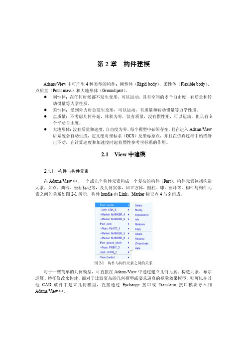
图 23 状态提示信息
(1)创建设计点。以设计点为基准定义空间位置来创建构件,是 Adams/View 中的常用 方法。可以通过对设计点的参数化处理,实现模型的参数化建模,在试验设计、研究和优化分 析中非常有用。
单击 Construction 中的 按钮,在模型树上方出现设计点的属性栏,如图 24 所示。
图 212 MSC Nastran Translate 设置
2.1.5 添加特征 创建了几何实体后,用户可以对其进行修饰处理,包括倒直角(Chamfer)、倒圆角(Fillet)、 钻孔(Hole)、凸圆(Boss)、抽壳(Hollow)等特征,如图 213 和表 21 所示。
图标
图 213 创建特征工具栏
构件建模
第2章
2.1.2 创建构造元素
构造元素包括设计点、标记点、圆、圆弧、直线、质量点、多段线和样条曲线。单击主工 具栏 Bodies>Construction,构造元素工具栏如图 22 所示。
图 22 构造元素工具栏
这些构造元素建模工具的使用方法大同小异,单击不同的按钮,工具界面状态栏会有相应 的提示信息,如图 23 所示,可根据状态栏的提示信息进行操作,下面介绍部分要素的使用方法。
2.创建拉伸体(Extrusion) 对于一些复杂的不规则的几何形体,可以使用此工具来创建。单击 Solids 工具栏中的 按钮,在模型树上方出现长方体属性栏,如图 29 所示。
23
MSC Adams 多体动力学仿真基础与实例解析
图 29 创建拉伸体对话框
在下拉列表框中有 New Part、Add to Part、On Ground 选项,分别表示所创建的拉伸体是 新创建、添加到已有的构件上或者属于地面。在 Profile 栏右侧可选择 Points、Curve 选项,分 别表示拉伸体截面可由点或曲线生成。
基于ADAMS平台的STANDFORD机器人三维建模和运动学仿真
杨孝杰·毕业设计
基于 ADAMS 为平台的 STANDFORD 机器人三维建模和运动学仿真
力的特种机器人和各种智能机器人。从某种意义上讲,一个国家机器人技术水平 的高低 反映了这个国家综合技术实力的高低。毋庸质疑,21 世纪机器人技术必 将得到更大的发展,成为各国必争之知识经济制高点。
1.2 工业机器人
机;国外已有模块化装配机器人产品问市。 3、工业机器人控制系统向基于 PC 机的开放型控制器方向发展,便于标准 化、网络化;器件集成度提高,控制柜日见小巧,且采用模块化结构;大大提高 了系统的可靠性、易操作性和可维修性。 4、机器人中的传感器作用日益重要,除采用传统的位置、速度、加速度等 传感器外,装配、焊接机器人还应用了视觉、力觉等传感器,而遥控机器人则采 用视觉、声觉、力觉、触觉等多传感器的融合技术来进行环境建模及决策控制; 多传感器融合配置技术在产品化系统中已有成熟应用。 5、虚拟现实技术在机器人中的作用已从仿真、预演发展到用于过程控制, 如使遥控机器人操作者产生置身于远端作业环境中的感觉来操纵机器人。 6、 当代遥控机器人系统的发展特点不是追求全自治系统,而是致力于操作 者与机器人的人机交互控制, 即遥控加局部自主系统构成完整的监控遥控操作系 统,使智能机器人走出实验室进入实用化阶段。 此外,机器人家族中还有医用机器人、军用智能机器人、娱乐机器人等。
2
杨孝杰·毕业设计
基于 ADAMS 为平台的 STANDFORD 机器人三维建模和运动学仿真
1.3
STANDFORD 机器人
STANDFORD 机器人 (如图 1-1 所示) 是一种具有 6 个自由度的新型机器人,
该机器人不仅能够灵活的实现六个自由度的三维空间运动,而且具有结构稳定、 承载能力强、 误差小、 位置精度高、 响应快等一系列突出优点, 其应用日益广泛, 应用领域不断拓展,使得 STANDFORD 机器人成为国际上备受关注的研究领域之 一。目前,对 STANDFORD 机器人运动学和动力学的分析多采用的是解析法,为了 更有效的发展该类机器人的研究成果, 有必要建立适当的模型并进行仿真从仿真 分析的角度,对其进行建模、仿真、分析,为 STANDFORD 机器人的研究提供了一 种新的方法。
用ADAMS进行蜗轮蜗杆模拟仿真示例
蜗轮蜗杆的啮合传动 蜗轮蜗杆的传动比如右图所表示,设在节点P 处蜗杆与蜗轮的速度 分别为1v 和2v ,由图中可知:112tan λ'=v v ,即11122tan λωω''=r r其中1r '为蜗杆的分度圆半径,2r为蜗轮的分度圆半径,1λ'为蜗杆节圆螺旋线的升角。
从而,1122112tan λωω''==r r i (1) 在本例子中,将介绍怎么在ADAMS 12.0中模拟创建过程⒈ 启动ADAMS双击桌面上ADAMS/View 的快捷图标,打开ADAMS/View 。
在欢迎对话框中选择“Create a new model ”,在模型名称(Model name )栏中输入:woluenwogan ;在重力名称(Gravity )栏中选择“Earth Normal (-Global Y)”;在单位名称(Units )栏中选择“MMKS –mm,kg,N,s,deg ”。
如图1-1所示。
图1-1 欢迎对话框 ⒉ 设置工作环境2.1 对于这个模型,网格间距需要设置成更高的精度以满足要求。
在ADAMS/View 菜单栏中,选择设置(Setting )下拉菜单中的工作网格(Working Grid )命令。
系统弹出设置工作网格对话框,将网格的尺寸(Size )中的X 和Y 分别设置成750mm 和500mm ,间距(Spacing )中的X 和Y 都设置成50mm 。
然后点击“OK ”确定。
如图2-1所表示。
2.2 用鼠标左键点击选择(Select )图标,控制面板出现在工具箱中。
2.3 用鼠标左键点击动态放大(Dynamic Zoom )图标,在 模型窗口中,点击鼠标左键并按住不放,移动鼠标进行放大或缩小。
⒊创建蜗轮3.1 在ADAMS/View 零件库中选择圆柱体(Cylinder )图标,参数选择为“New Part ”,长度(Length )选择100mm ,半径(Radius )选 择200mm(这里的长度和半径的选择没有特殊要求,可以选择不同的数字 )。
用adams进行仿真第六讲
增加发动机、车身后 整车多体动力学模型
用adams进行仿真第六讲
铁路车辆及装备
悬挂系统设计 磨耗预测 轨道载荷预测 货物加固效果仿真 物料运输设备设计 事故再现 车辆稳定性分析 临界车速预测 乘员舒适性研究
用adams进行仿真第六讲
结构噪声 仿真
双层车 模态仿真
温度场 仿真
D38轻量 化设计
强度 分析
ADAMS软件包括3个最基本的解题程序模块:A/View(基本环 境)、A/Solver(求解器)和A/PostProcessor(后处理)。 另外还有一些特殊场合应用的附加程序模块,A/Rail(机车模 块 ) 、 A/Driver( 驾 驶 员 模 块 ) 、 A/Tire( 轮 胎 模 块 ) 、 A/Linear(线性模块)、A/Flex(柔性模块)、A/Controls(控制模 块 ) 、 A/Car( 轿 车 模 块 ) 、 A/FEA ( 有 限 元 模 块 ) 、 A/Hydraulics ( 液 压 模 块 ) 、 A/Vibrations( 振 动 模 块 ) A/Exchange(接口模块)、A/Animation(高速动画模块)等。
产品概念设计
产品详细设计
用adams进行仿真第六讲
美国GM公司虚拟样机技术 戴维·陈是GM R&D虚拟样机(VP)的首席科学家,他的观点
值得考虑: ➢虚拟样机是一个方向,同时也是一个渐进过程; ➢产品设计的所有要求,用数学模型创建后,一定要验证,
用试验验证; ➢关键是建模(Creating Model),且应在专家指导下进行;
用adams进行仿真第六讲
m=5,k=2,c=1
用adams进行仿真第六讲
已知条件:假设系统处于零平衡位置,外力函数为幅 值为1 的阶跃函数。
ADAMS实例仿真解析
参考文献
【1】《虚拟样机技术与ADAMS应用实例教程》-----北京航空航天大学出版社。
【2】《MD ADAMS虚拟样机从入门到精通》---------机械工业出版社。
模型建立··························································3
约束添加··························································9
运动添加··························································11
模型仿真··························································14
小结······························································17
参考文献··························································17
小 结
通过利用ADAMS对旋转机的虚拟建模以及仿真分析,我们可以对选钻机的工作情况有一个较为真实的了解,对我们以后设计选钻机有很大的帮助,可以大幅度上减少我们的作业时间,极大地提高了我们的工作效率,而且很大程度上减少了设计错误。
ADAMS是一款虚拟仿真软件,一直受到各行各业的广泛青睐,对设计及分析有很大帮助,是工程上不可缺少的一款软件,而且在市场上,一直备受欢迎。ADAMS本身也在随着社会科技的发展不断更新,不断地为社会服务。
- 1、下载文档前请自行甄别文档内容的完整性,平台不提供额外的编辑、内容补充、找答案等附加服务。
- 2、"仅部分预览"的文档,不可在线预览部分如存在完整性等问题,可反馈申请退款(可完整预览的文档不适用该条件!)。
- 3、如文档侵犯您的权益,请联系客服反馈,我们会尽快为您处理(人工客服工作时间:9:00-18:30)。
Adams 实例建模仿真目录Adams课程论文 (1)第一章模型的建立 (2)1、模型的介绍 (2)2、启动ADAMS (2)3、栅格设置 (3)4、创建齿轮 (3)5、创建连杆 (5)6、创建滑块 (6)第二章创建转动副,移动副,齿轮副,驱动力,仿真 (7)1、创建转动副 (7)2、创建移动副 (8)3、创建齿轮副 (9)4、创建驱动力 (10)5、仿真 (11)第三章计算结果后处理 (12)1、滑块的速度曲线 (12)2、滑块位移曲线 (12)3、滑块加速度曲线 (13)4、齿轮1与齿轮2转角曲线 (13)5、连杆曲线图 (14)6、录制动画并导出 (15)第四章总结 (17)第一章模型的建立1、模型的介绍如图一所示,该模型由齿数z为200,模数m为4,半径400mm的齿轮1,齿数z为100,模数m为4,半径200mm的齿轮2,以及连杆和滑块组成。
该模型的运动形式为齿轮1为驱动轮,带动齿轮2转动,齿轮2于连杆偏心连接,带动连杆推动滑块直线反复运动。
实质上是将齿轮的转动转化为滑块的平动。
图1-1 模型简图2、启动ADAMS2.1 在桌面点击ADAMS快捷键Adams - View x64 2013,或者Windows开始菜单启动:“开始”—“所有程序”—“MSC.Software”—“Adams x64 2013”—“A View”—“Adams-View”。
2.2 启动后出现Welcome欢迎窗口,如图1-1所示,点击New Model,出现Create New Model,Model Name为adams,Gravity为Earth Normal,Units为MMKS。
2.3 单击OK,进入ADAMS。
图1-2 启动ADAMS3、栅格设置3.1 点击Setting,选择Working Grid。
3.2 弹出的窗口设置网格范围尺寸,如图1-2所示。
图1-3 修改栅格4、创建齿轮4.1 如图1-3所示,单击Bodies菜单栏中的圆柱体(Cylinder),在出现的对话框中设置圆柱的长度(Length)50mm和半径(Radius)400mm。
4.2 在点(0.0.0)处点击鼠标左键,然后上拉鼠标到点(0.50.0),生成圆柱体,即齿轮1的模型。
4.3 对齿轮1进行位置转换,如图1-4所示,在ADAMS/View中位置/方向库中选择位置旋转图标,在角度(Angle)一栏中输入90,表示将对象旋转90度。
4.4 选择PART2,出现白色箭头,依照图1-4的箭头方向点击鼠标,将齿轮1反转90度。
4.5 如图1-5所示,按3.1至3.4的方法同样创建齿轮2。
齿轮2的位置为(600.0.0),上拉鼠标到位置(600.50.0)。
图1-4 创建齿轮1图1-5 齿轮位置转换图1-6 创建齿轮25、创建连杆5.1 选择Bodies菜单栏中的Construction Geometry:Marker图标,创建标记(1250.50.0)。
点。
在如图1-6所示的位置创建两个标记。
标记位置分别为(750.50.0),5.2 左边菜单栏中鼠标右键选择MARKER3--Modify,跳出的对话框中修改Location为(750.50.-30),第二个标记点为(1250.50.-30)。
5.3 点击上方菜单栏中的Bodies中的连杆(Link),连杆第一个点选择MARKER3,第二个点选择MARKER4,生成如图1-6所示9位置的连杆。
图1-7 创建连杆6、创建滑块6.1 选择Bodies菜单栏中的Construction Geometry:Marker图标,创建标记点。
在如图1-7所示的位置创建标记。
标记位置为(1150.50.0)6.2 左边菜单栏中鼠标右键选择MARKER7--Modify,跳出的对话框中修改Location为(1150.50.-25)。
6.3 点击上方菜单栏中的Bodies中的箱体(BOX),设置箱体的Length=200mm,Height=200mm,Depth=200mm,各自前面的框框打勾。
6.4 在工作区中选择MARKER7,创建滑块,如图1-7所示7位置所示。
6.5 整体的几何模型侧面形状如图1-7右下方图片所示。
图1-8 创建滑块第二章创建转动副,移动副,齿轮副,驱动力,仿真1、创建转动副1 选择ADAMS/View约束库中的旋转副(Joint: Revolute)的图标,参数选择2 Bod-1 Loc和Normal To Grid。
在 ADAMS/View工作窗口中先用鼠标左键选择齿轮1(PART2),然后选择机架(ground),接着选择齿轮1上的PART_2.cm,如图2-1所示的2位置处,图中显亮的部分就是所创建的旋转副(JOINT_1) ,该旋转副连接机架和齿轮1,使齿轮1能相对机架旋转。
2选择ADAMS/View约束库中的旋转副(Joint: Revolute)的图标,参数选择2 Bod-1 Loc和Normal To Grid。
在 ADAMS/View工作窗口中先用鼠标左键选择齿轮2(PART3),然后选择机架(ground),接着选择齿轮2上的PART3.cm,如图2-1所示的3位置处,图中显亮的部分就是所创建的旋转副(JOINT_2) ,该旋转副连接机架和齿轮2,使齿轮2能相对机架旋转。
3选择ADAMS/View约束库中的旋转副(Joint: Revolute)的图标,参数选择2 Bod-1 Loc和Normal To Grid。
在 ADAMS/View工作窗口中先用鼠标左键选择齿轮2(PART3),然后选择连杆(PARK4),接着选择齿轮2上的MARKER3,如图2-1所示的4位置处,图中显亮的部分就是所创建的旋转副(JOINT_3) ,该旋转副连接连杆和齿轮2,使连杆能相对齿轮2旋转。
4选择ADAMS/View约束库中的旋转副(Joint: Revolute)的图标,参数选择2 Bod-1 Loc和Normal To Grid。
在 ADAMS/View工作窗口中先用鼠标左键选择滑块(PART5),然后选择连杆(PARK4),接着选择连杆上的MARKER4,如图2-1所示的5位置处,图中显亮的部分就是所创建的旋转副(JOINT_4) ,该旋转副连接连杆和滑块,使连杆能相对滑块旋转。
图2-1 创建转动副2、创建移动副选择ADAMS/View约束库中的移动副(Joint: Translational)的图标,参数选择2 Bod-1 Loc和Normal To Grid。
在 ADAMS/View工作窗口中先用鼠标左键选择滑块(PART5),然后选择机架(ground),接着选择滑块底边中点,如图2-2所示的3位置处,图中显亮的部分就是所创建的移动副(JOINT_5) ,该移动副连接滑块和机架,使滑块能相对机架旋转。
图2-2 创建移动副3、创建齿轮副3.1 创建齿轮啮合点。
选择ADAMS/View零件库中的标记点工具图标,参数选择如图3-1所示。
选择坐标为(400,100,0),如图3-1所示,图中显亮的部分就是创建的啮合点(MARTKER20)图2-3 创建齿轮啮合点3.2 对上面做出的啮合点进行位置移动和方位旋转,使该啮合点位于两齿轮中心线上,并使啮合点的Z轴方向与齿轮旋转方向相同。
在ADAMS/View窗口中,在两个齿轮啮合处点击鼠标右键,选择MARKER20--Modify,如图2-4所示。
在弹出的对话框中,将Location栏的值400.0, 50.0, 0.0改为400.0, 25, 0.0(位置移动),将Orientation栏中的值0.0, 0.0, 0.0修改为0, 90, 0(方位旋转)。
如图2-4所示。
点击对话框下面的OK键进行确定,旋转后的啮合点(MARKER20)如图2-4所示。
从图中可以看出,啮合点的Z轴(蓝色)Z轴的方向与齿轮的啮合方向相同。
图2-4 修改啮合点位置3.3选择ADAMS/View约束库中的齿轮副(Gear)图标,在弹出的对话框中的Joint Name栏中,点击鼠标右键分别选择JOINT_1、JOINT_2。
如图2-5所示。
在Common Velocity Marker栏中,点击鼠标右键选择啮合点(MARKER20)。
如图2-5 所示2位置处,然后点击对话框下面的OK按钮,两个齿轮的齿轮副创建出来,如图2-5所示3位置处。
图2-5 创建齿轮副4、创建驱动力在ADAMS/View驱动库中选择旋转驱动(Rotational Joint Motion)按钮,在Speed一栏中输入360,360表示旋转驱动每秒钟旋转360度。
在ADAMS/View 工作窗口中,选择左边的齿轮(黄色的),用鼠标左键点击齿轮上的旋转副(JOINT_1),一个旋转驱动创建出来,如图2-6所示3位置处,图中显亮的部分为旋转驱动。
图2-6 创建驱动力5、仿真点击仿真按钮,设置仿真终止时间(End Time)为1,仿真工作步长(Step Size)为0.001,然后点击开始仿真按钮,进行仿真。
图2-7 仿真第三章计算结果后处理1、滑块的速度曲线1.1点击仿真对话框右下角曲线绘图按钮(Plotting),进入绘图界面。
1.2如图3-1所示,依次鼠标右击Objects-Body-PART_5-CM_Velocity-X-Add生成速度曲线,由图可知该曲线为正弦曲线。
图3-1 滑块速度曲线2、滑块位移曲线2.1 如图3-2所示,依次鼠标右击Objects-Body-PART_5-CM_Position-X-Add Curves,生成速度曲线,由图可知,该曲线为余弦曲线。
图3-2 滑块位移曲线3、滑块加速度曲线3.1 如图3-2所示,依次鼠标右击Objects-Body-PART_5-CM_Accelration-X-Add Curves,生成加速度曲线。
图3-3 滑块加速度曲线4、齿轮1与齿轮2转角曲线4.1点击Measure,选择Math中的angle,选择JOINT_1,然后点击Add Curves,生成齿轮1的转角曲线图。
4.2 点击Measure,选择Math中的angle,选择JOINT_2,然后点击Add Curves,生成齿轮2的转角曲线图。
4.3如图3-4所示,齿轮2的转角是720度,齿轮1的转角是360度.因为齿轮2的齿数为50,模数为4,半径为200mm,齿轮1的齿数为100,模数为4,半径为400mm,所以齿轮一转一圈,齿轮2要转两圈。
图3-4 齿轮转角曲线5、连杆曲线图5.1 图3-5到图3-9所示分别为连杆的位移,速度,加速度,角速度,角加速度的曲线图。
3-5 连杆位移曲线3-6 连杆速度曲线3-7 连杆加速度曲线图3-8 连杆角速度曲线3-9 连杆角加速度曲线6、录制动画并导出6.1 在Plotting左上角,把Plotting换成Animation。