
四以太网口协转说明书
(A)
指示灯
前面板共有十七个有效指示灯,分别为:
名称
指示灯 功能
状态
设备工作状态
PWR
电 源 连 接 状 亮 设备的电源正常工作
态指示
灭 无电源输入本设备
LINK1~ 以 太 网 连 接 亮 以太网口有连接
LINK4 状态指示
灭 以太网口无连接
闪亮 以太网有收发数据
SPD1~
亮 以太网口工作在 100M
或 -38 VDC ~ - 72 VDC 6、功耗: 台式设备<5W
机框设备<75W 7、工作条件:温度 -40℃ ~ +70℃ 湿度 95%
无腐蚀性和溶剂性气体,无扬尘,无强磁场干扰。 8、台式设备尺寸: 台式设备有两种尺寸可选:
7
台式/机架式 FE1-4Eth(A)操作手册
218mm*136mm*44mm
一般安全要求
请阅读下列安全注意事项,以避免人身伤害,并防止 本产品或与其相连接的任何其他产品受到损坏。为了避免 可能发生的危险,本产品只可在规定的范围内使用。
只有我公司授权的技术人员方可执行维修。
防止火灾或人身伤害
使用适当的电源。仔细核对产品的电源类型以及正负极
性。
正确的连接和பைடு நூலகம்开。当设备正处于上电状态时,请勿随
3) 排除E1故障后,确定整条链路以太网口的工作状 态。以太网口的工作模式有5种,根据用户需要可以设置。
4) 当网线接入 FE1-4Eth(A)的时候,设备的 LINK 灯
4
台式/机架式 FE1-4Eth(A)操作手册
应该正常点亮,F/D、SPD 灯是根据用户设置来定是否点亮。 如果还是不亮,请检查网线是否按做线方式要求做。设备 的四个以太网口可以任意选择使用,无须任何设置。
操作手册
一、功能简介
设备主要包括两个方面: ① 上行口为 E1 的交换式网桥 ② 还是一种高性能、自学习式远程以太网桥。它 体积小、成本低,很适宜对成本敏感的桥接应
5
台式/机架式 FE1-4Eth(A)操作手册
用,或作为比特流基础结构上的局域网延伸器 或分段器。 设备能不间断地学习与其相连的局 域网上的 MAC 地址,并根据数据帧的目的 MAC 地址来决定是否能发还是过滤。 ③ FE1-4EthA 支持 OP-FE1(必须设置成 PCM31 状 态)和 OP-4Eth 三级组网,并能进行 SNMP 全程 网管。
避免接触裸露电路。产品有电时,请勿触摸裸露的接点
和部件。
在有可疑的故障时,请勿操作。如怀疑本产品有损坏, 请让我公司授权的维修人员检修。 提供良好的通风环境。 请勿在潮湿环境下操作。 请勿在易爆环境中操作。 保持产品表面清洁和干燥。
快速操作指南
FE1-4Eth(A)产品是上行口为 E1 的交换式网桥,在 E1 上传输以太网的数据包。以太网工作状态有 5 种工作模式 可设。同时也可设置包长、通道隔离和掉线自检功能。E1 口的工作状态是 75Ω和 120Ω自适应,无需通过开关设置。
警
灭 E1 线路接收正确
PTOK
伪随机码检
表示本端处于测试状态,且
亮
测指示
伪随机码检测通过
灭 表示没有检测到伪随机码
TEST
测试状态指
表示处于测试状态,本端或
亮
示
远端有测试按钮被按下
灭 当前处于正常工作状态
注:本端设备 E1 有告警,本端的 E1LOS、E1SYL 灯常亮,
远端的这两个灯闪亮。
拨码开关 设备的阻抗是自适应,用户根据需要选择相应的物理
8
台式/机架式 FE1-4Eth(A)操作手册
SPD4
以太网工作
以太网口工作在 10M
灭
速率指示
F/D1~ 双 工 工 作 状 亮 以太网口工作在全双工
F/D4
态指示
灭 以太网口工作在半双工
E1LOS E1 线路断码 亮 E1 线路断码告警
告警
灭 E1 线路正常工作
E1SYL E1 帧失步告 亮 E1 数据帧失步
FE1-4Eth(A)
FE1-4Eth(A)
无特殊要求,根据出厂默认设置直接连接 5) 当设备工作在100M时,要求用户将与其对接的网络设 备的流控打开,别的工作状态,流控不做任何限制。 6) 设备以太网口是交叉直通自适应,方便用户可以任意 使用直通线或者交叉线,免去重新做线的麻烦。 7) 设备正常工作时,PWR与LINK灯常亮,F/D、SPD灯视 情况而定(指工作的以太网口),其余灯和不工作的以太 网口灯都灭。 8) 设备出厂时按钮开关设置无效,如果要起作用,将第 5位拨码开关置"ON"方可生效。 9) 均按以上操作,并参见了使用手册说明,但设备还是 不能正常工作,请与供应商或办事处的技术人员联系。
一、功能简介 ................................................5 二、产品特点 ................................................6 三、技术参数 ................................................7 四、前面板示意图 ........................................8
台式/机架式 FE1-4Eth(A)操作手册
目录
前 言 ................................................................2 一般安全要求 ........................................................3 快速操作指南 ........................................................4 操作手册 ................................................................5
二、产品特点
① 支持 1600 长包,支持 ISL 协议 ② 以太网口有 10M/半双工、10M/全双工、100M/半双
工、100M/全双工、自适应五种工作模式 ③ E1 接口 75Ω非平衡/120Ω平衡自适应 ④ 支持本端环回、向对端环回二种环回方式,支持线
路伪随机码测试 ⑤ 以太网口支持交叉线直通自动识别,免去重新做线
三、技术参数
1、G.703接口
* 速率: 2048Kbit/s
* 码型: HDB3码 * 阻抗: 75Ω非平衡/120Ω平衡自适应 * 接口特性: 满足G.703、G.704等标准 * 连接器: Q9(75Ω)、RJ45或RJ48-C(120Ω) * 帧结构: 成帧 2、Ethernet接口 * 速率:10M/100M自适应 * 双工模式:全/半双工可以设置 * 以太网口数量:4个 * 以太网口做线要求:直通交叉自适应 3、环回功能: 支持本端环回和 PATT 伪随机码检测, 配合使用用于检测 E1 线路。 4、电压选择:台式设备 AC 220V、 DC -48V 兼容 机框:AC220V 或 DC-48V,有热备份功能。 5、可波动电压: 180 VAC~260 VAC
意连接或断开数据线。
产品接地。为了防止电击,接地导体必须与地面相连,
在与本产品输入或输出终端连接前,应确保本产品已正确 接地。
正确的连接。用户在连接使用时请使用出厂配备的辅配
件。如用户做特殊连接时请注意拐角分配要求。 请勿在无设备盖板时操作。如盖板或面板已卸下,请勿操 作本产品。
3
台式/机架式 FE1-4Eth(A)操作手册
我公司的协议转换系列产品是针对这一实际问 题而设计的,这一系列中所包含的多种多样的转换 器能通过在不同接口间提供转换来克服上述矛盾。
我公司的系列产品具有集成度高、可靠性强、 功耗低、体积小、功能齐全等特点,还有丰富的告 警指示助于工程开通,有着广泛的应用前景。根据 应用需求,转换形式可包括下述一种或多种
1
台式/机架式 FE1-4Eth(A)操作手册
前言
数据通信标准经协商一致、发表并为众人遵循。 其最终目的是为了确保来自不同国度不同生产厂家 的设备之间能实现通信。遗憾的是,各种通信网络 如计算机通信网(LAN或WAN),传统电信网(PSTN) 等,由于发展的时期及背景有所不同,再加上其它 一些历史原因,很多时候为了实现同一目的却产生 了众多不一的标准。例如:G703、V.35、X.21、V.36、 RS-422和RS-530都用于高速通信而且在功能上差异 甚微,但它们却有着不同的电气和物理特性。许多 现存的标准妨碍直接通信,要求设备之间有一中介 设备。
1) 根据后面板上电源标识接入正确电源,开机轻 触电源开关至相应位置。如果开关上显示“48V”,表示 用户使用-48V的直流电源;如果开关上显示“220V”,表 示用户使用220V的交流电源。
2) 根据E1线路要求,选择需要的物理接口,本设备 的E1收与对端设备的发相连,发与收相连,线路上应没有 E1告警,如果有,可以通过E1环回来确定故障源。我公司 设备须成对使用。
(两台设备并排放置,通过台式设备侧面的插槽,配上选
订的支架可上标准的 19 英寸机架) 251.8mm*141.6mm*47.5mm
(通过选订的支架可上标准的 19 英寸机架) 机框设备尺寸:483mm*165mm*177mm (可上标准的 19 英寸机架) 9、台式和机架式的设备共用一块板子,用户可以根据 需要将台式的设备改成机架,反之亦然。
1)电气的——转换信号电平 2)物理的——提供不同型式的插头 3)功能的——转换信号的功能 4)速率的——从一种速率转换成另外一种
版本号:V1.07
2
台式/机架式 FE1-4Eth(A)操作手册
台式/机架式 FE1-4Eth(A)使用说明
HR-SWG20244S 28 口千兆管理型以太网交换机说明书

HR-SWG20244S28口千兆管理型以太网交换机【产品概述】HR-SWG20244S是28口千兆管理型以太网交换机,提供24个千兆下联网口+4个千兆上联SFP光口+1个Console口;交换容量高达192Gbps;二层网络管理功能,支持路由、DHCP、VLAN、MAC地址、ACL访问控制、QoS、组播、风暴抑制、IPV4/IPV6等业务功能;支持环网,极速检测及自愈功能;支持802.1X认证、ARP入侵检测、IP源防护、DoS防护等安全控制策略;支持STP/RSTP/MSTP生成树协议、动/静态链路汇聚等网络保护功能;支持Web/Telnet/CLI/SSH等多种管理维护方式;采用黑色铁质外壳设计;DC12V电源接入;面板上有LED指示灯,可以动态显示设备连接和运行,提供简单的故障检测方法,轻巧简便;主要应用于工业园区、楼宇、厂矿、政府机关、社区等用户网络的以太网接入/汇聚层。
【主要特点】支持24个千兆下联网口+4个千兆上联SFP光口+1个管理端口符合IEEE802.3、IEEE802.3u、IEEE802.3ab、IEEE802.3z标准存储转发交换机制,整机交换容量高达192Gbps二层网络管理,支持路由/DHCP/VLAN/MAC地址/ACL/QoS等业务功能支持环网功能,极速检测及自愈功能支持802.1X认证、ARP入侵检测、IP源防护、DoS防护等安全控制策略支持STP/RSTP/MSTP生成树协议、动/静态链路汇聚等网络保护功能支持WEB、TELNET、CLI、SSH、SNMP网络维护管理方式【应用环境】城域光纤宽带网:电信、有线电视、网络系统集成等数,据网络运营商宽带专网:适用于金融、政府、石油、铁路、电力、公安、交通、教育等行业专网多媒体传输:图像、话音、数据综合传输、适用于远程教学、会议电视、可视电话等应用 实时监控:实时控制信号、图像及数据同时传输【技术指标】【订购信息】【产品效果图】。
以太网转4E1协议转换器说明书

以太网转4E1协议转换器说明书QS-RJ45-4E1接口转换器采用反向复用技术,将多条E1电路捆绑起来用于传输10M/100M的以太网数据,实现了1-4路E1通道至以太网接口之间的相互转换,此转换器能把E1通道收发的信号点对点传输到RJ45接口,实现E1信道与以太网的互连。
与一般的远程网桥不同的是,此转换器支持1-4路E1信道的灵活配置,能自动检测E1的数量并选择可用的E1,并且允许E1电路之间存在一定的传输时延差。
单路线路速率是1968Kbit/s,4路带宽可达7872Kbit/s。
设备在10/100Mbps全/半双工方式下使用时,可与以太网交换机或集线器相连,充分地利用电信网络中现有的大量E1电路资源来扩展以太网的传输距离和应用范围,是以太网宽带接入一个很好的解决方案。
此产品可用于局域网互连、局端互连、视频点播、远程监控、交换机的E1接口插卡等各种领域。
关键特性:基于自主知识产权的集成电路;实现以太网数据在1~4条E1电路中的透明传输;以太网接口10M/100M,全/半双工完全自适应,支持VLAN协议;每路以太网口支持支持AUTO-MDIX(交叉线和直连线自适应);可设置CRC告警门限自动对传输质量差的线路进行隔离,并且是单方向切断,当2M支路一个方向误码率超出门限时,只切断该方向,另一方向不受影响;即以太网传输的两个方向可以不对称;实允许4路E1 有10ms 的传输时延差。
当该差值超出允许的范围时,系统可以自动停止在时延过大的E1 上发送数据;真正实现SNMP 的网管功能;提供2种环回功能:E1本端自环、E1向外环;内置动态以太网MAC 地址列表(4096个),具有本地数据帧过滤功能;E1接口符合ITU-T G.703、G.704和G.823,不支持信令时隙的使用;E1接口模块含有内置的时钟恢复电路和HDB3编解码电路;设备工作中支持E1信道的热插拔,并自动检测有效的E1信道,中间不会中断数据传输;支持1至4路E1的灵活配置,在复位时自动检测E1的数量和时延并选择可用的E1;支持本地系统对远端系统的复位;有以太网监控自动复位功能,不会死机;网管接口采用SNMP 。
协转说明书

6、达诚协转换器-6:
分为RJ45接口和V.35接口两个部分。
1、RJ45,成帧:前面板共有4位按钮开关,16位拨码开关
FE1-Eth协议转换器告警指示灯说明如下:
按钮开关功能说明:
ANA: 从本端的E1口向用户口环回,用于检测设备及连接线是否正常
DIG: 从本端的用户口向E1口环回,用于检测对端设备及E1线路。
REM: 命令远端环回,由于该命令必须通过E1线路送到对端才能生效,所以有两种情况此命令无效:第一种情况是设备工作在不成帧状态如E1-ETH(所有时隙都用来传输用户口的数据,此时用户口的速率为2048K);第二种情况是对端不是本设备。
PATT: 伪随机码检测功能。
前面板共16位拨码开关,其功能说明如下:
2.以太网协议转换器的网络拓扑图如下:
3.
2、V.35,成帧:前面板共有4位按钮开关,16位拨码开关
1.V.35协议转换器的图示及说明如下
按钮开关功能说明:
ANA: 从本端的E1口向用户口环回,用于检测设备及连接线是否正常
DIG: 从本端的用户口向E1口环回,用于检测对端设备及E1线路。
REM: 命令远端环回,由于该命令必须通过E1线路送到对端才能生效,所以有两种情况此命令无效:第一种情况是设备工作在不成帧状态如E1-ETH(所有时隙都用来传输用户口的数据,此时用户口的速率为2048K);第二种情况是对端不是本设备。
PATT: 伪随机码检测功能。
2.其网络拓扑图如下:。
Orion VCL-4 以太网1E1到E1接口转换器用户手册说明书
VCL-4 Ethernet over 1E14*10/(100) Base-T to E1 Interface ConverterData Sheet & User ManualORION TELECOM NETWORKS INC.RIONTELECOMNETWORKSHeadquarters: Phoenix, Arizona Orion Telecom Networks Inc.20100, N 51st Ave, Suite B240,Glendale AZ 85308Phone: +1 480-816-8672Fax: +1 480-816-0115E-mail:**********************Website: Regional Office: Miami, Florida Orion Telecom Networks Inc.4000 Ponce de Leon Blvd. Suite 470,Coral Gables, FL 33146 U.S.A.Phone: 1-305-777-0419, Fax: 1-305-777-0201E-mail:**********************Website: WarrantyThis Orion product is warranted against defects in material and workmanship for a period of one year from the date of shipment. During the warranty period, Orion will, at its discretion, either repair or replace products, which prove to be defective. For warranty service or repair, this product must be returned to a service facility designated by Orion. The buyer shall prepay shipping charges to Orion and the company shall pay shipping charges to return the product to the buyer. However, the buyer shall pay all the shipping charges, duties and taxes for products returned to Orion from another country.Limitation of WarrantyThe foregoing warranty shall not apply to defects resulting from improper or inadequate maintenance by the buyer, the buyer-supplied firmware or interfacing, unauthorized modification or misuse, operation outside of the environmental specifications for the product or improper site preparation or maintenance.Exclusive RemediesThe remedies provided herein are the buyer's sole and exclusive remedies. Orion shall not be liable for any direct, indirect, special, incidental or consequent damages, whether based on contract or any legal theory.NoticeThis manual contains information that is proprietary to Orion T elecom Networks Inc. No part of this publication may be reproduced in any form whatsoever without prior written approval by Orion T elecom Networks Inc.Safety WarningsThe exclamation point within a triangle is intended to warn the operator or service personnel of operation and maintenance factors relating to the product and its operating environment, which could pose a safety hazard.Always observe standard safety precautions during installation, operation and maintenance of this product. Only qualified and authorized service personnel should carry out adjustment, maintenance or repairs to this instrument. No adjustment, maintenance or repairs should be performed by either theoperator or the user.!INDEXThe VCL-4 Ethernet over 1E1 Converter provides the user a facility to transport Ethernet (multiple LANs) over an E1 link. The equipment converts and transports upto 4 x Ethernet links over an E1 in a shared* mode, or a discrete** mode, depending on the user's preference and selection.*In shared mode: All 4 Ethernet channels are transported over the same shared E1 link and areallowed full access to each other's path. The usermay select this mode if the user desires that all of the 4 x Ethernet links that are being transported over the same E1 to optimally share its bandwidth resources and where discretion is essential.*In discrete mode: All 4 Ethernet channels are transported over the same E1 link, but without allowing intrusion or access to each other's path. The user may select the discrete* mode when the user desires to transport all 4 Ethernet channels over the same E1 line discretely, and without allowing access to each other.The equipment shall always be installed and used in pairs, with one terminal being installed at either end (each side) of the network.The VCL-4 Ethernet over 1E1, 4*10(100)Base-T to E1 Interface Converter is an ethernet extension device utilizing TDM telecom infrastructure (the telecom network of E1s, or of PDH, SDH and E1/E3/SDH microwave etc. carrying E1s).The VCL-4 Ethernet over 1E1, 4*10(100)Base-T to E1 Interface Converter converts the Ethernet Data into E1 frame format for transmission over the existing TDM (E1) links and then re-converts the E1s back into Ethernet Data at the far-end terminal. It function is to primarily provide a BRIDGE between two Ethernet LANs over the existing E1 based telecom network. The device can effectively utilize the redundant bandwidth of telecom operators' existing TDM network to transport Ethernet data with low investment.*Optional powers 220V AC and -48V DC. May be ordered with either power option.DescriptionApplicationsThis equipment may be used for the following purposes:1.Bridging Ethernet LANs over existing TDM (E1) telecom network. Extending Ethernet Networks utilizing TDM (E1) landline based telecom infrastructure.2.Using telecom network of E1s / PDH / SDH Microwave etc. carrying E1s to transport Ethernet Data.In all these cases the equipment be always installed and used in pairs, with one terminal beinginstalled at either end (each side) of the network.VCL-4 Ethernet over 1E1VCL-4 Ethernet over 1E1Description and ApplicationsShared link modeIn the "shared link mode", each LAN can view and talk to other LANs. Example: each LAN can view and talk to all other LANs at same site or the corresponding remote side. This mode may be selected for use if bandwidth optimization and usage is of prime importance and the user is not averse to sharing the E1 link resources with the other LANs being transported on the same E1 link.For example all four Ethernet Ports at local site are in LAN Mode and will also communicate to all four Ethernet Ports at far end site.T ypical ApplicationNote:In the "shared link mode", the VLAN switch must be OFF (The ethernet ports are notisolated to each other on both sides of the E1 link).Note: Each DIP Switch is ON in downside and OFF in upside.POWERConverter in V LAN Mode “shared link mode”E1NetworkE1Network E1E1VCL-4 Ethernet over E1VCL-4 Ethernet over E1VCL-4 Ethernet over 1E1T ypical ApplicationPOWERDiscrete link modeIn the "discrete link mode" each LAN is bridged to, and can only talk to its corresponding LAN on the remote side. It can not talk to any other LAN either at same side or the remote side. This mode may be selected for use if the users do not wish to share the E1 link resources with the other LANs being transported on the same E1 link.For example the Ethernet Port 1 (at local site) will communicate to Ethernet Port 1 at far end site and so on for Port 2 etc.Example: In the discrete link mode , the LAN 1 (Ethernet Port 1 of the equipment) only can talk to the corresponding LAN 1 (Ethernet Port 1 of the equipment) at remote side and can not talk to any other LAN, either on remote side or same side.Note: In the discrete link mode , the VLAN switch must be ON (Ethernet Ports isolated) in Boththe units.Note: Each DIP Switch is ON in downside and OFF in Upside.Converter in “discrete link mode”E1NetworkE1Network E1E1VCL-4 Ethernet over E1VCL-4 Ethernet over E1VCL-4 Ethernet over 1E1Discrete Link ModeVCL-4 Ethernet over 1E1Technical features T echnical Features1.The maximum transmission rate of 4 Ethernet data over E1 links is2.048 Mbit/s2.Supporting 1600 long frames, accordance with Interior Switching Link (ISL) Protocol3Supporting local E1 port loop-back4.The Ethernet Port is self-adaptive to crossover or Straight/Parallel cable to avoid the trouble of re-wiring5.Supports up to four Ethernet Ports. Supports port mask6.Ethernet auto negotiation function. Supports 10M/100M and working modes of bothfull-duplex and semi-duplex7.T ransparently transmits ultra-long frames stipulated in IEEE 802.1Q, and supports Ethernetswitches with VLAN function8.Imbedded, dynamic Ethernet MAC address list (1024 addresses), and filter function forlocal data frames9.Can support multiple LANs of different network addresses10.Optional powers 220V AC and -48V DC. May be ordered with either power option.E1 Port SpecificationsNumber of E1 Ports`OneLine Rate E1 (2.048 Mbps ± 50 bps)Framing Framed / Un-Framed / Multi-FramedElectrical As per ITU-T G.703Jitter As per ITU-T G.823Impedance 120 Ohm (RJ-45)Impedance75 Ohm (BNC)Ethernet Port SpecificationsNumber of Ports FourPort T ypes10/100BaseT (Auto-negotiating)Standards Compliance IEEE 802.3Data Rate10/100BaseT transmission rate limitedto 2.048Mbps (maximum)Connectors RJ-45 (10/100 BaseT Electrical)VCL-4 Ethernet over 1E1Installation and Commissioning Installation and Commissioning1. Qualifying the network!The time-slots should be configured according to the planning of E1 link. If the accessed E1 link is being exclusively and only by this equipment (i.e. VCL-4 Ethernet over E1, 4*10(100)Base -T to E1 Interface Converter), it should be configured as transparent transmission to increase Ethernet service bandwidth*** Note: Due care must be taken to ensure that the settings meet the user requirements of “shared line" or "discrete line" service!The remote time-slots shall be configured in accordance with the local time-slots. The configuration of the equipment on both sides should be the same!The length of the Ethernet cable shall not exceed 100m2.Grounding!When the equipment is used with the AC~220V power supply, the 3-core socket must be grounded for protection!The other equipment (e.g. optical terminal) connected with this equipment must also be grounded to earth for protection3.InstallationStep 1 Power up the Ethernet over E1 (IPoTDM) equipment.Important: Please ensure that Ethernet over E1 (IPoTDM) equipment is powered-up prior to connecting the ethernet and the E1 links.Step 2 Connect E1 line after ensuring that transmission device, port converter and ethernet switch have been grounded.A Bit Error Rate (BER) test may be conducted on E1 link using a BERT tester to ensure that the E1 errors are within the permitted limits / threshold.Step 3 Please configure the Ethernet Mode of the Ethernet over E1 (IPoTDM) equipment at both sides as well as the Ethernet Ports of the devices that are connected to the Ethernet over E1 (IPoTDM) equipment. Connect the ethernet links.The equipment is used to bridge Multiple LANs. Please ensure that the connecting LANs on both sides of the link are operating in the same IP domain.Step 4 Ping over the ethernet connection from one side to the other (near-end to the far-end) to verify the link.Important Note: Please power-up the equipment prior to connecting the ethernet and the E1 links.VCL-4 Ethernet over 1E1Front Panel Description of the Front Panel1.Front PanelOutline of the front panel is as follows:POWERPower LED: The GREEN LED indicator lights of power supply is lit under normal working condition when the power supply is connected.VCL-4 Ethernet over 1E1Definition of Indications Definition of IndicatorsStatus of Ethernet Port LEDsIndicator light Port 1Port 2Port 3Port 4Link LED GREEN Input Signal Input Signal Input Signal Input Signal "ON" (Solid)Detected Detected Detected DetectedLink LED GREEN Receiving/ Receiving/ Receiving/Receiving/ "ON" (Flashing)Sending Data Sending Data Sending Data Sending Data10/100M "Green" Port under Port under Port under Port under100M service 100M service 100M service 100M servicemode mode mode mode10/100M "OFF” Port under Port under Port under Port under10M service 10M service 10M service 10M servicemode mode mode modeDup/Col "ON" Port under Port under Port under Port under (Solid)full-duplex full-duplex full-duplex full-duplexmode mode mode modeDup/Col "OFF" Port under Port under Port under Port under (Solid)semi-duplex semi-duplex semi-duplex semi-duplexmode mode mode modeDup/Col "OFF" Ethernet Port Ethernet Port Ethernet Port Ethernet Port (Flashing)has detected has detected has detected has detectedany conflict any conflict any conflict any conflicterror error error errorStatus ofIndicator light E1 Circuit LED Alarm and statusE1 LOS RED "ON"E1 port is unconnected or bad connectedE1 LOS RED "OFF"E1 port is connected properlyAIS YELLOW "ON"1's code alarm of E1 lineAIS YELLOW "OFF"OKDIP switch settings on front panel are as followsSwitch Description Default 1 (CLK)ON Internal clock: The system is running on its internal clock ONOFF Line clock: The system is drawing clock from E1 line.2 (RLOOP)ON No loop-back on E1 interface.ONOFF E1 Interface is loop-back.3 (AUTO)ON Ethernet Port is running in self-adaptive mode.ONOFF Ethernet Port rate is depend on SPD4 (SPD)ON Ethernet Port rate is 100M if "AUTO" is off ONOFF Ethernet Port rate is 10M if "AUTO" is off5 (DPX)ON Ethernet Port is running in full-duplex mode ONOFF Ethernet Port is running in semi-duplex mode6 and 7Speed Limit configuration of Ethernet Interface(SPLD 1 and SPLD 1SPLD 2 Port Speed limit ON SPLD 2)ON ON None port is speed limitON OFF 1 and 2 port speed, limit 512 K; 3 and 4 port, noSpeed limitOFF ON 1 port speed limit, 1M; 2,3 and 4, no speed limit.OFF OFF Speed limit, 512 K for all ports8 (VLAN)ON Ethernet Port isolated (discrete link mode)OffOFF Ethernet Port is not isolated (Share link mode)Note: Each DIP Switch is ON in downside and OFF in Upside.Power supply switch: T o switch the power OFF/ON.2.(A) Back Panel - AC InputThe back panel of 4Ethernet over E1 (IPoTDM) equipment is as follows with AC Input:(B) Backpanel - DC InputThe back panel of 4Ethernet over E1 (IPoTDM) equipment is as follows with -48V DC Input:DIP switch settings on Back panel!E1 socket for 120 Ohms balanced: All DIP switches MUST be OFF (upside)!E1 socket for 75 Ohms unbalanced: All DIP switches MUST be ON (downside)AC220V: represents the unit uses AC~220V power supply.*Optional powers 220V AC and -48V DC. May be ordered with either power option.E1 RJ-45 Pinouts Details120W RJ45 pin-outPIN No.Definition of function Signal Direction 1NC2 TX+ (transmitted data +)E1 Data Output3TX- (transmitted data -)E1 Data Output4NC5NC6RX+ (received data +)E1 Data Input7RX- (received data -)E1 Data Input8NCEthernet RJ-45 PinoutsEthernet RJ-45 PinoutsPIN No.Definition of function Signal Direction 1TX+ (transmitted data +)Data Output2TX- (transmitted data -)Data Output3RX+ (received data +)Data Input4NC5NC6RX- (received data -)Data Input7NC8NCTime-slot configuration of E1 port: For E1 time-slot configuration, the DIP Switch settings on the bottom panel are as follows:The time-slot DIP switches located at the bottom of the equipment marked with TS0~TS31 bits corresponding to 0~31 time-slots of E1 channel.Note: It is recommended to set the TS0 DIP switch OFF .3. Bottom PanelThe Bottom panel of 4Ethernet over E1 (IPoTDM) equipment is as follows:Working Mode Switch SettingUnframedAll switches are set to OFFFramed (CCS/PCM-31)S0 set to OFF , and the occupied time slots to ON Multi-Framed (CAS/PCM-30 )All switches S0~S31 set to ON but S16 is set to OFFExample 1: If you wish to use only first 5 time-slots then you need to set the S0 time-slots to OFF and switch S1 to S5 to ON and time-slot S16 will be set to ON.Example 2: If you wish to carry first 8 time-slots on 512Kbps, then you need to set the S0 time-slot OFF and switch S1 to S8 to ON (i.e. since each time-slot consumes 64Kbps, so 8 time-slots will consume 8 x 64Kbps = 512Kbps) and time-slot S16 will be set to ON.Example 3: If you wish to carry 20 time-slots on 1.28Mbps (64Kbps x 20) then you need to set time slot S0 OFF and S1 to S21 time-slots to ON. Please remember that the time-slot S16 will be used as signaling time-slot.VCL-4 Ethernet over 1E1Bottom PanelVCL-4 Ethernet over 1E1Installation Instructions and Trouble-Shooting Installation Instructions and T rouble-shootingA Installation Instruction1.Perform the following tests prior to usage:Inspect every configuration switch on the panels to see whether they are set in normalworking state, i.e. PWR and E1 LOS light ON; in the case of framed E1, E1SYL shall be ON,other lights OFF.2.Arrange E1 line impedance and time-slots as required, plug in E1 input/output lines andEthernet line, then turn ON the power supply, the equipment comes into normal workingconditions.3.One equipment MUST be set to master clock and other MUST be set to line clock(loop-timed).B T rouble-shootingWhen the equipment is under normal working conditions, the three indication lights, E1LOS E1SYL and AIS, shall be OFF.1.T rouble: E1LOS light ONCheck point: make E1 loop-back at E1 input port and output port, if the light OFF, thenhighlight the check on E1 input line. Please check with the E1 Cable.2T rouble: E1SYL light ONCheck point: Make E1 loop-back at E1 input port and output port, if the light OFF, thenhighlight the check on the opposite-end interface converter to see whether set to framingservice mode. If the opposite side interface converter has been set to framing service mode,check the transmission path of E1 for any disconnect. The alarm is valid if port is working on framing mode.3.T rouble: AIS light ONCheck point: normally this fault is due to either of the following reasons:1. The opposite-end E1 equipment cuts off receiving.2. There are other devices working under test on E1 transmission line.3. E1 Channel is in loop-back state.VCL-4 Ethernet over 1E1General Parameters 4.T rouble: LINK light OFFCheck point: This fault is basically due to the error in making network (crossover orstraight-through) cable. Please check if the equipment I require crossover cable or straight-through cable you are connecting to. VCL-4 Ethernet over E1 is self-adaptive to crossover or straight-through cable.5.T rouble: LINK light in normal state, but data PING failsCheck point:1. Check whether the state of the equipment Ethernet is in accordance with thatof the opposite-end Ethernet; If not then, cancel the self-adaptive state ofEthernet Interface and change compulsorily to configure speed and duplexso as to be in accordance with the other end.2. Check whether the equipment E1 port or E1 transmission channel is underloop-back or other test conditions, if any, then cancel it.3. Check whether the time slot configuration of the local equipment is inaccordance with the remote one. If not then, configure it to be in accordance.6.T rouble: Data succeed in PING, but with frame lossCheck point: This fault may be due to the following reasons:1. Incompatible configuration of E1 port impedance.2. Incomplete physical connection of E1 port, e.g. only one pole connected atreceiving end.3. Wrong configuration of clock, change the clock to master clock.7.T rouble: The communication is normal prior to configure port mask, but blocked after portmask configuration.Check point: Ensure whether the remote equipment also configured port mask, whether the port mask configuration at two ends is in accordance; after port mask configuration, onlyEthernet of same port number can perform communications. Check whether VLAN switch set to OFF (shared link mode is ON) the equipment connected to Ethernet interface, if any, T oggle the VLAN switch to ON (set the equipment for discrete link mode).General1.Power SupplyAC Mains Input : 220V 20% (AC Mains input model).*Optional powers 220V AC and -48V DC. May be ordered with either power option.Power Consumption: <10W2.Service Conditions00Working temperature: -5C ~ +50C00Storage temperature: -20C ~ +70CRelative humidity: 5 % ~ 95% (at 35C)Do not subject the equipment to corrosive solvents, gas, dust or intense magnetic-fieldinterference.3.Dimensions : 200mm x 150mm x 40mm4.Weight : 0.86 Kg.Note:1 The equipment shall always be installed and used in pairs, with one terminal beinginstalled at either end (each side) of the network.2Operation and maintenance of network equipment require professional knowledge and experience. We recommend the equipment to be managed only by qualified technicians.Should you require technical assistance please consult the provider, or contact ourSUPPORT DESK at ************************T echnical specifications are subject to changes without notice.Windows is the registered T rademark of Microsoft Corporation, USA.Revision 06 - November 30, 2012.VCL-4 Ethernet over 1E1SupportHeadquarters: Phoenix, Arizona Orion Telecom Networks Inc. 20100, N 51st Ave, Suite B240, Glendale AZ 85308Phone: +1 480-816-8672Fax: +1 480-816-0115E-mail:********************** Website: Regional Office: Miami, Florida Orion Telecom Networks Inc.4000 Ponce de Leon Blvd. Suite 470, Coral Gables, FL 33146 U.S.A. Phone: 1-305-777-0419,Fax: 1-305-777-0201E-mail:********************** Website: 。
UT-2204 四口RS-485智能数据 转换器说明书

123UT-2204RS-485四口智能数据转换器说明书一、产品概述:UT-2204RS-485RS-485(HUB)115.2KBPS RS-485RS -485RS-4851200UT-2204RS-485HUB RS-485RS-485RS-485UT-2204RS-485HUB RS-485是一款专为解决复杂环境下系统要求而设计的总线分割集线器。
该产品支持传输速率最高达,内置数据缓存和微处理器,供电采用外接开关电源供电,安全可靠,非常适合工程应用。
在工作模式,采用的判别电路能够自动感知数据流方向,并且自动的切换使能控制电路,轻松解决收发转换时问题。
接口传输距离大于米、性能稳定。
广泛应用于视频监控等系统中,是一款性能优良的数据接口转换产品。
提供星型总线连接。
用户可以轻易改善总线结构,分割网段,提高通信可靠性。
这一性能大大提高了现有网络的可靠性,有效缩短了网络的维护时间。
合理的利用可以助您设计出独特的高可靠的系统。
延二、性能参数:1EIA/TIA RS-232C RS-485、接口特性:接口兼容的、标准2RS-232C DB9/F RS-485、电气接口:接口为插座接口为接线端子345(PWR )(TXD1)(TXD2)(RXD1)(RXD2)(E1-E4)61200BPS-115.2KBPS7RS-23215KV ESD RS-4851500W 80-1.2115200-1200BPS 9DC9-30V 1A 10210mm 140mm 32mm11-40855%95%、传输介质:双绞线或屏蔽线、工作方式:异步半双工、信号指示:九个信号指示灯电源、发送、、接收、、故障、传输速率:、保护等级:接口±保护接口雷击浪涌保护、传输距离:公里()、工作电源:、尺寸:××、使用环境:℃到℃,相对湿度为到三、产品面板及信号指示:UT -2204RS-232Setup SIGNAL OUT DC9-30V RS-485INPUT RS-485OUTPUT 的前面板共有九个指示灯,后面板有接线端子和插座,口为设置波特率用(详见软件设置说明书),为报警继电器输出,电源输入插座及接线端子,和为数据通信接口。
艾维通 BB-USOPTL4-2P 4P 4 通道 RS-232 转以太网转换器 使用手册说明书
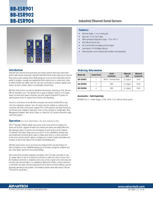
IntroductionIndustrial and commercial measurement and control systems often have stand-alone devices with unused serial ports. Advantech BB-ESRx Serial Servers allow you to connect those ports to your existing LAN or WAN, giving you access to more information and the ability to configure, manage and troubleshoot those devices from a control room, office or distant location via a WAN. Save the cost, time and trouble of carrying a laptop out to devices located in distant, dirty or uncomfortable environments.BB-ESRx Serial Servers are built for industrial environments, featuring an IP30, slim line, DIN rail mountable case. They operate from a range of voltages using AC or DC power, feature terminal block power connectors and even support redundant DC power. An external power source is required (not included, sold separately).Connect a serial device to the BB-ESRx serial port and connect the BB-ESRx to your LAN. Your networked computer ‘sees’ the device over the network as a virtual serial connection. BB-ESRx serial servers support TCP or UDP protocols and allow Transmit-to and Receive-from multiple IP addresses. There are four methods of configuration: Vlinx Management Software, Web Server, Telnet, or a direct RS-232 console connection using a terminal program.Operation(For more information, see user manual on CD.)Vlinx™ Manager software allows easy access to the serial server to configure the server and its ports, upgrade firmware and monitor port status and activity. When the Vlinx Manager opens, it searches for and displays all serial servers on the network. The Monitor Port feature allows you to use any PC on the LAN/WAN to actively view and troubleshoot communications status. It shows when there is a client connectionto the server and the client IP address. It displays the number of bytes transmitted and received, as well as the status of the hardware handshaking lines.BB-ESRx serial servers can be accessed and configured from any web browser (ie, Internet Explorer) on the LAN/WAN allowing you to remotely manage the software and your serial device and do off-site troubleshooting.Vlinx Serial Servers provide automatic resumption of the TCP data connection in caseof a power failure or loss of an Ethernet connection on either the client or server. Once the Heartbeat connection is established, the server sends a signal to the client every five seconds until communication is re-established. Without this feature, a device that loses a connection and stops communicating would not be able to reconnect without a person physically attending to the problem. The Heartbeat feature works with virtual COM and TCP direct IP connections.• Ethernet enable 1, 2 or 4 serial ports• Data rate: 110 to 230.4 kbps• Wide operating temperature range: -10 to +80 °C• IP30 DIN rail mount case• RS-232/422/485 full-duplex and half-duplex• Auto detects 10/100 Mbps Ethernet• External power source required (not included, sold separately)FeaturesAccessories – Sold SeparatelyBB-MDR-40-12 – Power Supply, 12 Vdc, 40 W, 3.33 A, DIN rail mount, plastic BB-ESR904BB-ESR901 BB-ESR902 BB-ESR904。
智能设备开发有限公司的专用四口千兆以太网开关说明书
• 4 Gigabit Ethernet ports• Wide voltage input range: +5V to +30V DC - can be powered by a variety of sources• Industrial temperature range: -40ºC to +80ºC/-40ºF to +176ºF - works in extreme conditions• Redundant dual power inputs - reduces risk of power outage• Jumbo Frame support upto 9K frames • Integral DIN mountIntegral DIN mount and slim design takes up minimal cabinet spaceNon conducting polyamide casing with removablenumbered power terminal for easy wiring+5 to +30 Volt power input enables the device to be runfrom a standard car battery -ideal for in vehicle applications COMPACT INDUSTRIAL 4 PORT GIGABIT ETHERNET SWITCHSW-514Easy Wire Removable screw terminal blockJumbo Frame support up to 9K framesDual redundant power input: +5VDC to +30VDCPower consumption is optimised based on the status of the link deviceAll Ethernet ports are Auto MDI/MDIX supporting straight through or crossover Ethernet cablesCOMPACT INDUSTRIAL 4 PORT GIGABIT ETHERNET SWITCHSW-514Automatic detection of data transmission speed: 10 or 100 or 1000 MbpsIntegral DIN mount with groundNon-conducting polyamide case -40ºC to +80ºC/-40ºF to +176ºF temperature rangeConnectorsScrew Terminals 3.5mm pitch, #22 - #14, 0.5mm 2-2.5mm 2 pin power supplyWire Thickness0.150 inch, 3.81mm, 20 pins, 12+8 screw terminals, #26 - #16 AWG, 0.14mm 2-1.3mm 2Power SupplyPower Consumption 3.6W Max: 550mA@+5VDC/90mA@+30VDCPower Supply input Unregulated +5V to +30Volts DC, reverse polarity protection Isolation1500V RMS Magnetic isolation from Ethernet EnvironmentalOperating Temperature -40ºC to +80ºC/-40ºF to +176ºF Storage Temperature-40ºC to +80ºC/-40ºF to +176ºF Ambient Relative Humidity 5 to 95% (non-condensing)Magjack LED Information Link/ActivitySolid Connection established Flashing Data communication SpeedYellow 1000Mbps Green100MbpsEthernetEthernet Port 4 x RJ45 jack, 10/100/1000Mbs autosensing, crossover auto sensing (Auto MDIX)Protection 1,500 Volts magnetic isolation between ports HousingIP-20 rated non-conducting polyamide caseCompact case - all round smallprofileCOMPACT INDUSTRIAL 4 PORT GIGABIT ETHERNET SWITCHSW-514Lifetime Warranty and Support:We can help with every aspect of your project, from getting you up and running to custom application.Power Terminal Pin OutsPIN FUNCTION 1-V 2+VA 3+VB 4-V5Functional EarthEthernet Ports x4 Pin OutsPIN FUNCTION 1TxRxA+2TxRxA-3TxRxB+4TxRxC+5TxRxC-6TxRxB-7TxRxD+8TxRxD-© Brainboxes 2020BBSW260220COMPACT INDUSTRIAL 4 PORT GIGABIT ETHERNET SWITCHSW-514SW RangeSwitch products available in a range of formats and specifications.PW-650Power supply with USBconnector and prewired screw terminal block. Suitable for use with 5V USB ports.PW-600Power supply with connectors for UK, USA, EU and AUS mains socket. ‘Tails’ are suitable for connecting to screw terminal blocks.Packaging Information Packaging Quick Start Guide DeviceEthernet Switch 4 port Packaged Weight 0.19 kg, 5.64 ouncesPackaged Dims 160x135x49 mm, 6.3x5.3x1.9 inches GTIN Universal Code 837324004854ApprovalsIndustry Approvals Microsoft Certified Gold Partner, WEEE, RoHS, AEO (C-TPAT), CE, UKCA, METL Complies with UL62368-1Product Support Warranty Lifetime - online registration requiredSupportLifetime web, email and phone support from fully qualified, friendly staff who work in and alongside the Product Development TeamAdditional Information OEM option Available for bulk buy OEMMade In Manufactured in Great Britain (GB) by Brainboxes - Winner 2005 European Electronics Industry Awards ‘Manufacturer of the Year’CustomisableBrainboxes operate a ‘Perfect Fit Custom Design’ policy for volume users. Moreinfo:********************。
5.协议转换器系列说明书
ZY系列部分数据产品说明书V1.2北京正有网络通信技术股份有限公司Beijing Zhengyou Network &Communication Technology CO.,LTD一、综合概述本说明书主要阐述正有ZY系列部分数据产品的使用说明。
本说明书涉及到的数据产品包括:ZYTR-10/100M-OP网桥转换器和ZYTR-10/100M-E1网桥转换器;ZYEQ-OPE1型光端机;ZYTR-OP/V.35型转换器。
●ZYTR-10/100M-E1网桥转换器高性能自学式以太网桥。
它将一个以太网段的数据流通过E1通道传输到另一个以太网段,达到局域网延伸器的作用,并且该设备亦支持超长帧传输、具备流量可控制的功能。
●ZYTR-10/100M-OP网桥转换器是高性能自学式以太网桥。
它作为局域网延伸器,可将一个以太网段的数据流通过光纤通道传输到另一个以太网段,并且该设备亦支持超长帧传输、具备时隙可选配功能。
●ZYEQ-OPE1型光端机是以超大规模集成电路ZYIC-019为核心构成的光电合一传输设备。
可提供面向电信的E1传输,面向LAN和WAN的光纤解决方案。
●ZYTR-OP/V.35型转换器是以大规模集成电路为核心构成的V.35至光的转换设备。
V.35可直接连接数据终端或复用器、路由器的WAN端口,可组成专网或进行广域网连接。
V.35数据速率从64K—2048K可选。
1.1 性能特点:●ZYTR-10/100M-OP网桥转换器:提供一个光口;过滤和转发速率达每秒15,000帧;10,000MAC地址表;支持超长数据帧透明传输;提供1个UTP口,可接网卡和HUB(正反线自适应),支持10/100M自适应,全半双工;内置交流220V或直流-48V电源,可选配。
●ZYTR-10/100M-E1网桥转换器:提供一个E1口;流量可选,过滤和转发速率达每秒15,000帧;10,000MAC地址表;支持超长数据帧透明传输;提供1个UTP口(正反线自适应),支持10/100M自适应,全半双工;●ZYEQ-OPE1型光端机:提供一个光口和一个E1口;功耗低,可靠性高;提供E1远端环回测试功能;采用收发一体光器件。
IBM Flex System EN2024 4端口1Gb以太网适配器说明书
®IBM Flex System EN2024 4-port 1Gb Ethernet Adapter for Power SystemsIBM Redbooks Product GuideThe IBM Flex System™ EN2024 4-port 1Gb Ethernet Adapter is a quad-port Gigabit Ethernet network adapter that is supported on all IBM Power Systems compute nodes. When it is combined with the IBM Flex System EN2092 1Gb Ethernet Scalable Switch, clients can use an end-to-end 1 Gb solution on the IBM Flex System Enterprise Chassis. The EN2024 adapter is based on the Broadcom 5718 controller and offers a PCIe 2.0 x1 host interface with MSI/MSI-X.Figure 1 shows the adapter.Figure 1. IBM Flex System EN2024 4-port 1Gb Ethernet AdapterDid you know?This EN2024 is based on the industry-standard PCIe architecture and is ideal for customers that are using Gigabit Ethernet in their network infrastructure. The IBM Flex System compute nodes support up to two of these adapters for a total of eight NICs per system.Part number informationThe following table lists the ordering part number and feature code for the adapter.Table 1. Ordering part number and feature codeDescription Feature code(e-config)IBM Flex System EN2024 4-port 1Gb Ethernet Adapter1763The EN2024 4-port 1Gb Ethernet Adapter part number includes the following items: One adapter●Documentation CD●Important Notices flyer●FeaturesThe IBM Flex System EN2024 4-port 1Gb Ethernet Adapter has the following features: Dual Broadcom BCM5718 ASICs●Quad-port Gigabit 1000BASE-X interface●Two PCI Express 2.0 x1 host interfaces, one per ASIC●Full-duplex (FDX) capability, which enables simultaneous transmission and reception of data on the ●Ethernet networkMSI and MSI-X capabilities, up to 17 MSI-X vectors●A total of 17 receive queues and 16 transmit queues●A total of 17 MSI-X vectors that support per-queue interrupt to host●Function Level Reset (FLR)●ECC error detection and correction on internal SRAM●TCP, IP, and UDP checksum offload●Large Send offload, TCP segmentation offload●Receive-side scaling●Virtual LANs (VLANs): IEEE 802.1q VLAN tagging●Jumbo frames (9 KB)●IEEE 802.3x flow control●Statistic gathering (SNMP MIB II, Ethernet-like MIB [IEEE 802.3x, Clause 30])●Comprehensive diagnostic and configuration software suite●ACPI 1.1a-compliant: multiple power modes●Wake-on-LAN (WOL) support●Preboot Execution Environment (PXE) support●RoHS-compliant●Supported serversThe following table lists the IBM Flex System compute nodes that support the adapters.Table 2. Supported serversFor more information about the expansion cards that are supported by each blade server type, see this IBM® ServerProven website:/servers/eserver/serverproven/compat/us/I/O adapter cards are installed in the slot in supported servers (such as the x240) as shown in the following figure.Figure 2. Location of the I/O adapter slots in the IBM Flex System p270 Compute NodeSupported I/O modulesThese adapters can be installed in any I/O adapter slot of a supported IBM Flex System compute node. One or two compatible 1 Gb or 10 Gb I/O modules must be installed in the corresponding I/O bays in the chassis. The following table lists the switches that are supported. When connected to the 10 Gb switch or pass-thru module, the internal switch ports operate at 1 Gb speeds.To maximize the number of usable adapter ports, you might also need to order switch upgrades to enable morel ports as listed in the table. Alternatively, for CN4093, EN4093R, and SI4093 switches, you can use Flexible Port Mapping, which is a new feature of Networking OS 7.8 that allows you to minimize the number of upgrades needed. For more information, see the Product Guides for the switches that are available at this website:/portals/puresystems?Open&page=pg&cat=switchesThe table also specifies how many ports of the adapter are supported after the indicated upgrades are applied. Switches should be installed in pairs to maximize the number of ports enabled and to provide redundant network connections.Table 3. I/O modules and upgrades for use with the EN2024 4-port 1Gb Ethernet AdapterDescription Featurecode(e-config)Port count (per pairof switches)*1 Gb switchesIBM Flex System EN2092 1Gb Ethernet Scalable Switch + EN2092 1Gb Ethernet Scalable Switch (Upgrade 1) 35983594410 Gb switchesIBM Flex System Fabric CN4093 10Gb Converged Scalable Switch + CN4093 10Gb Converged Scalable Switch (Upgrade 1) ESW2ESU14IBM Flex System Fabric EN4093R 10Gb Scalable Switch + EN4093 10Gb Scalable Switch (Upgrade 1)ESW735964IBM Flex System Fabric EN4093 10Gb Scalable Switch + EN4093 10Gb Scalable Switch (Upgrade 1)359335964IBM Flex System EN4091 10Gb Ethernet Pass-thru37002IBM Flex System Fabric SI4093 System Interconnect Module + SI4093 System Interconnect Module (Upgrade 1)ESWAESW84IBM Flex System EN4023 10Gb Scalable Switch+ IBM Flex System EN4023 10Gb Scalable Switch (Upgrade 1) or Flex System EN4023 10Gb Scalable Switch (Upgrade 2)ESWDESWEESWF4Cisco Nexus B22 Fabric Extender for IBM IBM Flex System ESWB2* This column indicates the number of adapter ports that are active if indicated upgrades are installed. The adapter does not support the IBM Flex System EN6131 40Gb Ethernet Switch I/O module.The following table shows the connections between adapters that are installed in the compute nodes to the switch bays in the chassis.Table 4. Adapter to I/O bay correspondenceI/O adapter slot in the serverPort on the adapter Corresponding I/O module bay in the chassis Port 1Module bay 1Port 2Module bay 2Port 3*Module bay 1Slot 1Port 4*Module bay 2Port 1Module bay 3Port 2Module bay 4Port 3*Module bay 3Slot 2Port 4*Module bay 4Port 1Module bay 1Port 2Module bay 2Port 3*Module bay 1Slot 3(full-wide compute nodes only)Port 4*Module bay 2Port 1Module bay 3Port 2Module bay 4Port 3*Module bay 3Slot 4(full-wide compute nodes only)Port 4*Module bay 4* Ports 3 and 4 require Upgrade 1 of the EN2092 1Gb or EN4093 10Gb switch. The EN4091 Pass-thru only supports ports 1 and 2 (and only when two I/O modules are installed).The connections between the adapters that are installed in the compute nodes to the switch bays in the chassis are shown in the following figure. The figure shows half-wide servers, such as the p270 with two adapters.Figure 3. Logical layout of the interconnects between I/O adapters and I/O modulesOperating system supportThe IBM Flex System EN2024 4-port 1Gb Ethernet Adapter supports the following operating systems: AIX Version 6.1●AIX Version 7.1●IBM i 6.1●IBM Virtual I/O Server●Red Hat Enterprise Linux 6 for IBM POWER●SUSE LINUX Enterprise Server 11 for IBM POWER●Support for operating systems is based on the combination of the expansion card and the blade server on which it is installed. See the IBM ServerProven website for the latest information about the specific versions and service packs supported. Select the blade server, and then select the expansion card to see the supported operating systems: /systems/info/x86servers/serverproven/compat/us/WarrantyThere is a 1-year, customer-replaceable unit (CRU) limited warranty. When installed in a server, these adapters assume your system’s base warranty and any IBM ServicePac® upgrade.Physical specificationsThe adapter features the following dimensions and weight:Width: 100 mm (3.9 inches)●Depth: 80 mm (3.1 inches)●Weight: 13 g (0.3 lb)●The adapter features the following shipping dimensions and weight (approximate):Height: 58 mm (2.3 in)●Width: 229 mm (9.0 in)●Depth: 208 mm (8.2 in)●Weight: 0.4 kg (0.89 lb)●Regulatory complianceThe adapter conforms to the following standards:United States FCC 47 CFR Part 15, Subpart B, ANSI C63.4 (2003), Class A●United States UL 60950-1, Second Edition●IEC/EN 60950-1, Second Edition●FCC - Verified to comply with Part 15 of the FCC Rules, Class A●Canada ICES-003, issue 4, Class A●UL/IEC 60950-1●CSA C22.2 No. 60950-1-03●Japan VCCI, Class A●Australia/New Zealand AS/NZS CISPR 22:2006, Class A●IEC 60950-1(CB Certificate and CB Test Report)●Taiwan BSMI CNS13438, Class A●Korea KN22, Class A; KN24●Russia/GOST ME01, IEC-60950-1, GOST R 51318.22-99, GOST R 51318.24-99, GOST R●51317.3.2-2006, GOST R 51317.3.3-99IEC 60950-1 (CB Certificate and CB Test Report)●CE Mark (EN55022 Class A, EN60950-1, EN55024, EN61000-3-2, EN61000-3-3)●CISPR 22, Class A●Popular configurationsThe adapters can be used in various configurations. The following figure shows EN2024 4-port 1Gb Ethernet Adapters that are installed in both slots of the p270 (a model without the Embedded 10Gb Virtual Fabric Adapter), which in turn is installed in the chassis. The chassis also has four IBM Flex SystemEN2092 1Gb Ethernet Scalable Switches, each with Upgrade 1 installed to enable 28 internal ports. Figure 4. Example configurationThe following table lists the parts that are used in the configuration.Table 5. Components used when connecting the adapter to the 10 GbE switchesDescription Quantity Machine type /Feature Code7954-24X IBM Flex System p270 or other supported server 1 to 14 1763IBM Flex System EN2024 4-port 1Gb Ethernet Adapter 2 per server 7893-92X IBM Flex System Enterprise Chassis13598IBM Flex System EN2092 1Gb Ethernet Scalable Switch 43594IBM Flex System EN2092 1Gb Ethernet Scalable Switch (Upgrade 1)4 Related publicationsFor more information, see the following resources:Product Guides for all Flex System switches:●/portals/flexsystem?Open&page=pg&cat=switchesProduct Guides for Flex System compute nodes:●/portals/flexsystem?Open&page=pg&cat=nodesIBM Redbooks® publication IBM Flex System Products and Technology for Power Systems:●/abstracts/sg248256.htmlIBM Redbooks Product Guides for Flex System servers and options:●/portals/flexsystem?Open&page=pgbycatIBM Configurator for e-business (e-config):●/services/econfig/ServerProven for Flex System:●/systems/info/x86servers/serverproven/compat/us/flexsystems.htmlNoticesThis information was developed for products and services offered in the U.S.A.IBM may not offer the products, services, or features discussed in this document in other countries. Consult your local IBM representative for information on the products and services currently available in your area. Any reference to an IBM product, program, or service is not intended to state or imply that only that IBM product, program, or service may be used. Any functionally equivalent product, program, or service that does not infringe any IBM intellectual property right may be used instead. However, it is the user's responsibility to evaluate and verify the operation of any non-IBM product, program, or service. IBM may have patents or pending patent applications covering subject matter described in this document. The furnishing of this document does not give you any license to these patents. You can send license inquiries, in writing, to:IBM Director of Licensing, IBM Corporation, North Castle Drive, Armonk, NY 10504-1785 U.S.A.The following paragraph does not apply to the United Kingdom or any other country where such provisions are inconsistent with local law: INTERNATIONAL BUSINESS MACHINES CORPORATION PROVIDES THIS PUBLICATION "AS IS" WITHOUT WARRANTY OF ANY KIND, EITHER EXPRESS OR IMPLIED, INCLUDING, BUT NOT LIMITED TO, THE IMPLIED WARRANTIES OF NON-INFRINGEMENT, MERCHANTABILITY OR FITNESS FOR A PARTICULAR PURPOSE. Some states do not allow disclaimer of express or implied warranties in certain transactions, therefore, this statement may not apply to you. This information could include technical inaccuracies or typographical errors. Changes are periodically made to the information herein; these changes will be incorporated in new editions of the publication. IBM may make improvements and/or changes in the product(s) and/or the program(s) described in this publication at any time without notice.Any references in this information to non-IBM Web sites are provided for convenience only and do not in any manner serve as an endorsement of those Web sites. The materials at those Web sites are not part of the materials for this IBM product and use of those Web sites is at your own risk.IBM may use or distribute any of the information you supply in any way it believes appropriate without incurring any obligation to you. Information concerningnon-IBM products was obtained from the suppliers of those products, their published announcements or other publicly available sources. IBM has not tested those products and cannot confirm the accuracy of performance, compatibility or any other claims related to non-IBM products. Questions on the capabilities of non-IBM products should be addressed to the suppliers of those products. This information contains examples of data and reports used in daily business operations. To illustrate them as completely as possible, the examples include the names of individuals, companies, brands, and products. All of these names are fictitious and any similarity to the names and addresses used by an actual business enterprise is entirely coincidental.Any performance data contained herein was determined in a controlled environment. Therefore, the results obtained in other operating environments may vary significantly. Some measurements may have been made on development-level systems and there is no guarantee that these measurements will be the same on generally available systems. Furthermore, some measurement may have been estimated through extrapolation. Actual results may vary. Users of this document should verify the applicable data for their specific environment. COPYRIGHT LICENSE:This information contains sample application programs in source language, which illustrate programming techniques on various operating platforms. You may copy, modify, and distribute these sample programs in any form without payment to IBM, for the purposes of developing, using, marketing or distributing application programs conforming to the application programming interface for the operating platform for which the sample programs are written. These examples have not been thoroughly tested under all conditions. IBM, therefore, cannot guarantee or imply reliability, serviceability, or function of these programs.© Copyright International Business Machines Corporation 2014. All rights reserved.Note to U.S. Government Users Restricted Rights -- Use, duplication or disclosure restricted byGSA ADP Schedule Contract with IBM Corp.This document was created or updated on December 12, 2014.Send us your comments in one of the following ways:Use the online Contact us review form found at:●/redbooksSend your comments in an e-mail to:●***************.comMail your comments to:●IBM Corporation, International Technical Support OrganizationDept. HYTD Mail Station P0992455 South RoadPoughkeepsie, NY 12601-5400 U.S.A.This document is available online at /redbooks/abstracts/tips1243.html . TrademarksIBM, the IBM logo, and are trademarks or registered trademarks of International Business Machines Corporation in the United States, other countries, or both. These and other IBM trademarked terms are marked on their first occurrence in this information with the appropriate symbol (® or ™), indicating US registered or common law trademarks owned by IBM at the time this information was published. Such trademarks may also be registered or common law trademarks in other countries. A current list of IBM trademarks is available on the Web at/legal/copytrade.shtmlThe following terms are trademarks of the International Business Machines Corporation in the United States, other countries, or both:IBM®Power Systems™Redbooks®Redbooks (logo)®The following terms are trademarks of other companies:Intel, Intel logo, Intel Inside logo, and Intel Centrino logo are trademarks or registered trademarks of Intel Corporation or its subsidiaries in the United States and other countries.Java and all Java-based trademarks are trademarks of Sun Microsystems, Inc. in the United States, other countries, or both.Other company, product, or service names may be trademarks or service marks of others.IBM Flex System EN2024 4-port 1Gb Ethernet Adapter for Power Systems11。
CANFDNET-400U高性能四通道CANFD总线转以太网转换器用户手册说明书
©2019 Guangzhou ZLG Microelectronics Technology Corp.,Ltd.CANFDNET-400U 用户手册CANFD 总线转以太网模块产品UM01010101 1.0.00 Data:2019/03/11修订历史目录1. 产品简介 (1)1.1产品概述 (1)1.2产品特性 (1)1.2.1强大的硬件 (1)1.2.2完善的功能 (1)1.2.3典型应用 (2)2. 产品规格 (3)2.1电气参数 (3)2.2工作温度 (3)2.3防护等级 (3)3. 机械尺寸 (4)4. 产品硬件接口说明 (6)4.1面板布局 (6)4.2状态指示灯 (6)4.3按键 (7)4.4电源接口 (7)4.5CANFD-bus接口 (7)4.6以太网接口 (9)4.7车载以太网接口 (9)5. 快速使用 (11)5.1设备连接 (11)5.2软件安装 (11)5.3打开设备配置工具 (11)5.4设备搜索 (12)5.5设备基本配置 (13)5.5.1配置网络参数 (13)5.5.2配置CAN(FD)通道参数 (14)5.5.3配置CAN(FD)转以太网参数 (14)5.5.4下载配置 (15)5.6连接ZCANPRO (16)6. 免责声明 (18)1. 产品简介1.1 产品概述CANFDNET-400U是广州致远电子有限公司开发的高性能工业级以太网与CAN(FD)-bus的数据转换设备,它内部集成了4路CAN(FD)-bus 接口、1路Ethernet 接口,1路车载双线以太网接口,自带成熟稳定的TCP/IP 协议栈,用户利用它可以轻松完成CAN(FD)-bus 网络和以太网网络的互连互通,进一步拓展CAN(FD)-bus 网络的范围。
CANFDNET-400U为工业级产品,可以工作在-40℃~85℃的温度范围内。
它具有一路100M/1000M自适应以太网接口,一路10M/100M车载双线以太网接口,4路CAN(FD)口通信最高波特率为5Mbps,具有TCP Server,TCP Client,UDP等多种工作模式,通过配置软件用户可以灵活的设定相关配置参数。