
力士乐比例伺服阀
Electric Drivesand Controls Hydraulics Linear Motion andAssembly Technologies PneumaticsServiceTable of contentsContents Page Features 1 Ordering details 2 Standard types 3 Symbols 3 Functional description, cross-section 4 Technical data 5 to 6 Electrical connections, plug-in connectors 7 Integrated valve electronics for type 4WRAE 8 Characteristic curves 9 to 11 Unit dimensions 12 to 15RA 29055/08.01 Replaces: 06.98Nominal sizes 6 and 10Series 2XMaximum operating pressure 315 bar (4600 PSI) Maximum flow 42 L/min (11 GPM) (NS 6) Maximum flow 75 L/min (19.8 GPM) (NS 10)Model4WRAE 6 …-2X/G24K31/.VFeatures– Direct actuated proportional valve for controlling the direction and volume of a fl ow– Actuation by means of proportional solenoids with central thread and removable coil– For subplate mounting: Porting pattern to DIN 24 340 form A, ISO 4401 and CETOP-RP 121 HNFPA T3.5.1M R1 and ANSI B93.7 D 03Subplates to catalog sheets RE 45 052 (NS 6) or RE 45 054 (NS 10) separate order, see pages 12 to 15– Spring centred control spool– Integrated control electronics, interface A1 or F1 for type 4WRAE– Control electronics for type WRA:• Electrical amplifi er VT-VSPA2-1-1X in Eurocard format (separate order), see RE 30 112• Digital amplifi er VT-VSPD-1-1X in Eurocard format (separate order), see RE 30 123Model 4WRA 10 …-2X/G24…K4/.Vwith plug-in connectors andassociated control electronics(separate order)4/2- and 4/3-way proportional directional valves, direct actuated, without electrical position feedback Model 4WRA and 4WRAE 1/162/16 Bosch Rexroth Corp. | Industrial Hydraulics 4WRA and 4WAE | RA 29055/08.01 Ordering details1)Other types of electrical protection on request2)Only for NS 6: for version “J” = sea water resistant only state “K31”SymbolsProportional directional valve without integrated Type WRA…Type WRA…Proportional directional valve with integratedNS 6Model Material no. 4WRA 6 E07-2X/G24K4/V00910780 4WRA 6 E15-2X/G24K4/V00904438 4WRA 6 E30-2X/G24K4/V00904439 4WRA 6 E1-15-2X/G24K4/V00954053 4WRA 6 E1-30-2X/G24K4/V00947835 4WRA 6 EA15-2X/G24K4/V00954054 4WRA 6 EA30-2X/G24K4/V00954055 4WRA 6 W07-2X/G24K4/V00928412 4WRA 6 W15-2X/G24K4/V00954056 4WRA 6 W30-2X/G24K4/V00954407 4WRA 6 W1-15-2X/G24K4/V00954057 4WRA 6 W1-30-2X/G24K4/V00954058 4WRA 6 WA15-2X/G24K4/V00954059 4WRA 6 WA30-2X/G24K4/V00935535 4WRAE 6 E07-2X/G24K31/A1V00954069 4WRAE 6 E15-2X/G24K31/A1V00954070 4WRAE 6 E30-2X/G24K31/A1V00954071 4WRAE 6 E1-15-2X/G24K31/A1V00954072 4WRAE 6 E1-30-2X/G24K31/A1V00954073 4WRAE 6 EA15-2X/G24K31/A1V00954074 4WRAE 6 EA30-2X/G24K31/A1V00954075 4WRAE 6 W07-2X/G24K31/A1V00954076 4WRAE 6 W15-2X/G24K31/A1V00954077 4WRAE 6 W30-2X/G24K31/A1V00954078 4WRAE 6 W1-15-2X/G24K31/A1V00954079 4WRAE 6 W1-30-2X/G24K31/A1V00954080 4WRAE 6 WA15-2X/G24K31/A1V00954081 4WRAE 6 WA30-2X/G24K31/A1V00954082NS 10Model Material no. 4WRA 10 E30-2X/G24K4/V00954060 4WRA 10 E60-2X/G24K4/V00954061 4WRA 10 E1-30-2X/G24K4/V00954062 4WRA 10 E1-60-2X/G24K4/V00954063 4WRA 10 EA30-2X/G24K4/V00954408 4WRA 10 EA60-2X/G24K4/V00954064 4WRA 10 W30-2X/G24K4/V00577424 4WRA 10 W60-2X/G24K4/V00954065 4WRA 10 W1-30-2X/G24K4/V00954066 4WRA 10 W1-60-2X/G24K4/V00954067 4WRA 10 WA30-2X/G24K4/V00954068 4WRA 10 WA60-2X/G24K4/V00952054 4WRAE 10 E30-2X/G24K31/A1V00933793 4WRAE 10 E60-2X/G24K31/A1V00954083 4WRAE 10 E1-30-2X/G24K31/A1V00954084 4WRAE 10 E1-60-2X/G24K31/A1V00954409 4WRAE 10 EA30-2X/G24K31/A1V00954085 4WRAE 10 EA60-2X/G24K31/A1V00954086 4WRAE 10 W30-2X/G24K31/A1V00954087 4WRAE 10 W60-2X/G24K31/A1V00954088 4WRAE 10 W1-30-2X/G24K31/A1V00953496 4WRAE 10 W1-60-2X/G24K31/A1V00954089 4WRAE 10 WA30-2X/G24K31/A1V00954090 4WRAE 10 WA60-2X/G24K31/A1V00954091Standard typesRA 29055/08.01 | 4WRA and 4WAE Industrial Hydraulics | Bosch Rexroth Corp.3/16Functional description, cross-sectionThe 4/2- and 4/3-way proportional directional valves are designed as direct operated components for subplate mounting. They are actuated by means of proportional solenoids with central thread and removable coil. The solenoids are controlled either by external control electronics (type WRA) or by integrated control electronics (type WRAE).Design:The valves basically consist of:– Housing (1) with mounting surface– Control spool (2) with compression springs (3 and 4)– Solenoids (5 and 6) with central thread– Optional integrated valve electronics (7)Valve with 2 spool positions:(Type 4WRA…A …)In principle, the funtion of this valve version corresponds to that of the valve with 3 spool positions. However, the valves with 2 spool positions are only fi tted with solenoid “a”. Instead of the 2nd proportional solenoid a plug (8.1) is fi tted for NS 6 or for NS 10 a cover (8.2).Functional description:– With the solenoids (5 and 6) de-energized, the control spool (2) is held in the central position by compression springs (3 and 4)– Direct actuation of the control spool (2) by energizing a proportional solenoidE.g. controlling of solenoid “b” (6)→ The control spool (2) is moved to the left in proportion to the electrical input signal→ Connection form P to A and B to T via orifi ce-like cross sections with progressive fl ow characteristics – De-energization of the solenoid (6) → The control spool (2) is returned to the central position by compression spring (3)Note for type 4WRA 6…-2X/…:Draining of the tank line is to be avoided. With the appropriate installation conditions, a back pressure valve is to be installed (back pressure approx 2 bar).4/16 Bosch Rexroth Corp. | Industrial Hydraulics 4WRA and 4WAE | RA 29055/08.01RA 29055/08.01 | 4WRA and 4WAE Industrial Hydraulics | Bosch Rexroth Corp.5/16 Technical data (for applications outside these parameters, please consult us!)GeneralValve type WRA WRAE Installation optional, preferably horizontalStorage temperature range °C (°F) – 20 to + 80 (-4 to 176)Ambient temperature range °C (°F) – 20 to + 70 (-4 to 158) – 20 to + 50 (-4 to 122) Weight NS 6 kg (lbs) 2.0 (4.4) 2.2 (4.8)NS 10 kg (lbs) 6.6 (14.5) 6.8 (15)Hydraulic (measured at p = 100 bar, with HLP46 at 40 °C ± 5 °C)Operating pressure Ports A, B, P bar (PSI) up to 315 (4600)Port T bar (PSI) up to 210 (3000)NS 6 L/min (GPM) 7, 15 and 26 (1.85, 3.96 and 6.87)Nominal fl ow qV nomat Δp = 10 bar NS 10 L/min (GPM)30 and 60 (7.92 amd 15.85)Max. permissible fl ow NS 6 L/min (GPM)42 (11) [80 (21) with double fl ow](GPM)75 (19.8) [140 (37) with double fl ow]10L/minNSPressure fl uid Mineral oil (HL, HLP) to DIN 51 524other pressure fl uids on request!Pressure fl uid temperature range °C (°F) – 20 to + 80 (-4 to 176) [preferably + 40 to + 50 (104 to 122)] Viscosity range mm2/s (SUS) 20 to 380 (97 to 1766) [preferably 30 to 46 (141 to 210)] Degree of contamination Maximum permissible degree Filter with a minimumof contamination of the retention rate ofp ressure fl uid is to NAS 1638 β≥ 75 is recommendedxclass 9 x = 10≤ 5Hysteresis %Reversal error % ≤ 1Response sensitivity % ≤ 0.5Technical data (for applications outside these parameters, please consult us!)Electrical Valve type WRA 1)WRAEVoltage typeDC Command value signal Voltage input …A1“ V ± 10 ± 10with type WRAE Current input …F1“ mA 4 to 20 4 to 20Max. current per solenoidA 2.5 2.5Solenoid coilCold value 20 °CΩ2 2resistance Max. warm value Ω 33Duty % 100Max. coil temperature 2) °C (°F) Up to 150 (302)Electrical connections WRA With component plug to DIN EN 175 301-803 and ISO 4400see page 7 Plug-in connector to DIN EN 175 301-803 and ISO 4400 3) WRAE With component plug to E DIN 43 563-AM6-3Plug-in connector E DIN 43 563-BF6-3/Pg11 3)Valve protection to DIN 40 050IP 65 with fi tted and locked plug-in connectorControl electronics For WRA Amplifi er in Eurocard format 3) VT-VSPA2-1-2X/… see RE 30 110 Amplifi er in Modular format VT-MSPA2-1-1X/… see RE 30 228Digital amplifi er in Eurocard format 3) VT-VSPD-1-2X see RE 30 523For WRAEIntegrated into the valves, see page 8 Analogue command value module V T- SWMA-1-1X/... see RE 29 902 Analogue command value module V T-SWMKA-1-1X/... see RE 29 903 Analogue command value module V T-SWKA-1-1X/... see RE 30 255Digital command value module V T HACD-1-1X ... see RE 30 143Supply voltage Nominal voltage VDC 244WRAE, Lower limiting value V 21 / 22194WRA 1) Upper limiting valueV 35Amplfi er currentI max A 1.81.8Note: For details regarding the environmental simulation test covering EMC (electro-magnetic compatibility),climate and mechanical loading see RE 29 055-U (declaration regarding environmental compatibility).1)With Bosch Rexroth AG control electronics2)Due to the occuring surface temperature of the solenoidcoils, the European Standards EN 563 and EN 982 must be taken into account!3)Separate order6/16 Bosch Rexroth Corp. | Industrial Hydraulics 4WRA and 4WAE | RA 29055/08.01Electrical connection, plug-in connectors For type WRA(without integrated control electronics – not for version “J ” = sea water resistant) Connection on component plug Connection on plug-in connectorPlug-in connectorCECC 75 301-803-A002FA-H3D08-G to DIN EN 175 301-803 and ISO 4400Solenoid a , color graySeparate order under material no. 00074683Solenoid b , color blackSeparate order under material no. 00074684For type WRAE(with integrated electronics and for version “J ” = sea water resistant)For pin allocation, see block circuit diagram on page 8Plug-in connector to E DIN 43 563-BF6-3/Pg11Separate order under material no. 00021267 (plastic version)RA 29055/08.01 | 4WRA and 4WAE Industrial Hydraulics | Bosch Rexroth Corp. 7/16Block circuit diagram/terminal allocation of the integrated control electronicsCom. value: Positive command value (0 to 10 V or 12 to 20 mA) at D and reference potential to E causes fl ow from P to A and B to T.Negative command value (0 to – 10 V or 12 to 4 mA) at D and reference potential to E causes fl ow from P to B and A to T.For valves with a solenoid on side …a“ (spool variant EA and WA ) reference potential to E and positive command value at D (NS 6: 4 to 20 mA and NS 10: 12 to 20 mA) causes fl ow from P to B and A to T.Connection cable: Recommendation: – up to 25 m cable length type LiYCY 5 x 0.75 mm 2 (80 ft)– up to 50 m cable length type LiYCY 5 x 1.0 mm 2 (160 ft) External diameter 6.5 to 11 mm (0.26 in to 0.44 in) Connect screen to PE only on the supply side.1)Slots C and F must not be connected!Integrated electronics(see below)Pin allocation of the component plugIntegrated control electronics for type WRAE2) PE is connected to the cooling body and the valve housing 3)Protective conductor screwed to the valve housing and cover4) Ramp can be externally adjusted from 0 to 2,5 s; the same applies for T up and T down 5) Output stages current regualted6)Low voltage detection is not carried out for component type 4WRAE 10-2X.4)SlotSignalSupply voltage A B 24 VDC (19 to 35 VDC)GND C n.c. 1)Differential amplifi er inputD E com. value (± 10 V / 4 to 20 mA)ref. potential Fn.c. 1)8/16 Bosch Rexroth Corp. | Industrial Hydraulics 4WRA and 4WAE | RA 29055/08.010506070908010030 (7.9)20 (5.3)10 (2.6)5432130404050 2050607090801005432130402030 20 1050607090801005432130402030 20 10 20304050607080901005432130 (7.9)20 (5.3)10 (2.6)40 (10.6)50 (13.2)60 (15.9)70 (18.5)203040506070809010032.45120 (5.3)40 (10.6)60 (13.2)80 (21.1)100 (26.4)Characteristic curves – measured with HLP46 at 40 °C ± 5 °C (104 °F ±41 °F) NS 6Command value in % →F l o w i n L /m i n (G P M ) →7 L/min nominal fl ow at 10 bar valve pressure differential (1.8 GPM at 145 PSI)Command value in % →F l o w i n L /m i n (G P M ) →15 L/min nominal fl ow at 10 bar valve pressure differential (3.9 GPM at 145 PSI)Command value in % →F l o w i n L /m i n (G P M ) →30 L/min nominal fl ow at 10 bar valve pressure differential (7.9 GPM at 145 PSI)1 Δp = 10 bar constant2 Δp = 20 bar constant3 Δp = 30 bar constant4 Δp = 50 bar constant5 Δp = 100 bar constantΔp = Valve pressure differential (inlet pressure p P minus loadpressure p L and minus return pressure p T )30 L/min nominal fl ow at 10 bar valve pressure differential (7.9 GPM at 145 PSI)60 L/min nominal fl ow at 10 bar valve pressure differential (13.2 GPM at 145 PSI)Command value in % →F l o w i n L /m i n (G P M ) →1 Δp = 10 bar (145 PSI) constant2 Δp = 20 bar (290 PSI) constant3 Δp = 30 bar (435 PSI) constant4 Δp = 50 bar (725 PSI) constant 5Δp = 100 bar (1450 PSI) constantΔp = Valve pressure differential (inlet pressure p P minus loadpressure p L and minus return pressure p T )Command value in % →F l o w i n L /m i n (G P M ) →Characteristic curves – measured with HLP46 at 40 °C ± 5 °C (104 °F ±41 °F)NS 10RA 29055/08.01 | 4WRA and 4WAE Industrial Hydraulics | Bosch Rexroth Corp. 9/16501001502502003004321567(725) (1450) (2175) (2900) (3625) (4350)405030(7.9)20(5.3)10(2.6)501001502502003004321567(725) (1450) (2175) (2900) (3625) (4350)30(7.9)20(5.3)10(2.6)50100150250200300432567302010(725) (1450) (2175) (2900) (3625) (4350)100908070605040302010040801201602000–1000 – 750 – 500 – 25020406080Characteristic curves – measured with HLP46 at 40 °C ± 5 °C (104 °F ±41 °F) NS 6Performance limit, nominal fl ow 7 L/min (1.8 GPM)Performance limit, nominal fl ow 15 L/min (3.9 GPM)Performance limit, nominal fl ow 30 L/min (7.9 GPM)F l o w i n L /m i n (G P M ) →1 Command value = 40 %2 Command value = 50 %3 Command value = 60 %4 Command value= 70 %5 Command value = 80 %6 Command value = 90 %7 Command value = 100 %Valve pressure differential in bar (PSI) →Transient functions with stepped form of electrical input signals Time in ms →Signal change in %Types WRA and WRAES t r o k e i n % →F l o w i n L /m i n (G P M ) →Valve pressure differential in bar (PSI) →F l o w i n L /m i n (G P M ) →Valve pressure differential in bar (PSI) →If the performance limits are exceeded then fl ow forces occur which lead to uncontrolled spool movements.10/16 Bosch Rexroth Corp. | Industrial Hydraulics 4WRA and 4WAE | RA 29055/08.01501000150250200300765432130 (7.9)20 (5.3)10 (2.6)40 (10.6)50 (13.2)60 (15.9)70 (18.5)(725) (1450) (2175) (2900) (3625) (4350)80 (21.1)90 (23.8)100 (26.4)5010001502502003007654321(725) (1450) (2175) (2900) (3625) (4350)3020 10 40 50 60 70Characteristic curves – measured with HLP46 at 40 °C ± 5 °C (104 °F ±41 °F) NS 10Performance limit, nominal fl ow 30 L/min (7.9 GPM)Performance limit, nominal fl ow 60 L/min (15.9 GPM)F l o w i n L /m i n (G P M ) →Valve pressure differential in bar (PSI) →F l o w i n L /m i n (G P M ) →Valve pressure differential in bar (PSI) →Transient functions with stepped form of electrical input signalsTime in ms →Signal change in %1 Command value = 40 %2 Command value = 50 %3 Command value = 60 %4 Command value = 70 %5 Command value = 80 %6 Command value = 90 %7 Command value = 100 %I f the performance limits are exceeded then fl ow forces occur which lead to uncontrolled spool movements.Unit dimensions: NS 6 – dimensions in millimeters (inches) Type 4WRA1 Valve housing2Proportional solenoid “a”3Proportional solenoid “b”4.1Plug-in connector “A”, colour grey, separate order,see page 74.2Plug-in connector “B”, colour black, separate order,see page 75 Name plate6R-ring 9.81 x 1.5 x 1.78 (ports A, B, P, T)7Plug for valves with one solenoid(2 switched positions, versions EA or WA)8Space required to remove the plug-in connector9Machined valve mounting surface,position of the ports to DIN 24 340 form A,ISO 4401 and CETOP-RP 121 H Subplates to catalogue sheet RE 45 052 and valve fi xing screws have to be ordered separately.Subplates:G341/01, G1/4 (SAE-4; 7/16-20)G342/01, G3/8 (SAE-6; 9/16-18)G502/01, G1/2 (SAE-8; 3/4-16)Valve fi xing screws: 4 of M5 x 50 DIN 912-10.9(10-24 UNC x 2”); MA= 8.9 Nm (6.56 lb-ft)Unit dimensions: NS 6 – dimensions in millimeters (inches) Subplates to catalogue sheet RE 45 052 and valve fi xing screws have to be ordered separately.Subplates: G341/01, G1/4 (SAE-4; 7/16-20) G342/01, G3/8 (SAE-6; 9/16-18) G502/01, G1/2 (SAE-8; 3/4-16)Valve fi xing screws: 4 of M5 x 50 DIN 912-10.9 (10-24 UNC x 2”); M A = 8.9 Nm (6.56 lb-ft)1 Valve housing2 Proportional solenoid “a”3 Proportional solenoid “b”4 Plug-in connector to E DIN 43 563-BF6-3/Pg11,separate order, see page 7 5 Name plate6 R-ring 9.81 x 1.5 x 1.78 (ports A, B, P, T)7 Plug for valves with one solenoid(2 switched positions, versions EA or WA ) 8 Integrated control electronics9 Space required for the connection cable and to removethe plug-in connector 10 Machined valve mounting surface,position of the ports to DIN 24 340 form A,ISO 4401 and CETOP-RP 121 HTypes 4WRAE .../...K31/ (V)Required surface fi nish ofmating pieceUnit dimensions: NS 10 – dimensions in mm (inches) 1 Valve housing2Proportional solenoid “a”3Proportional solenoid “b”4.1Plug-in connector “A”, color gray, separate order,see page 74.2Plug-in connector “B”, color black, separate order,see page 75 Name plate6Valve bleed screwNote: The valves are bled before delivery.7R-ring 13.0 x 1.6 x 2.0 (ports A, B, P, T)8Plug for valves with one solenoid(2 switched positions, versions EA or WA)9Space required to remove the plug-in connector 10Machined valve mounting surface,position of the ports to DIN 24 340 form A,ISO 4401 and CETOP-RP 121 H Subplates to catalogue sheet RE 45 054 and valve fi xing screws have to be ordered separately.Subplates:G66/01, G3/8 (SAE-6; 9/26-18)G67/01, G1/2 (SAE-8; 3/4-16)G534/01, G3/4 (SAE-12; 1-1/16-12) Valve fi xing screws: 4 of M6 x 40 DIN 912-10.9(1/4-20 UNC x 1-1/2”); MA= 15.5 Nm (11.4 lb-ft)Type 4WRAUnit dimensions: NS 10 – dimensions in mm (inches)Subplates to catalogue sheet RE 45 054 and valve fi xing screws have to be ordered separately.Subplates: G66/01, G3/8 (SAE-6; 9/26-18) G67/01, G1/2 (SAE-8; 3/4-16) G534/01, G3/4 (SAE-12; 1-1/16-12)Valve fi xing screws: 4 of M6 x 40 DIN 912-10.9 (1/4-20 UNC x 1-1/2”); M A = 15.5 Nm (11.4 lb-ft)1 Valve housing2 Proportional solenoid “a”3 Proportional solenoid “b”4 Plug-in connector to E DIN 43 563-BF6-3/Pg11,separate order, see page 7 5 Name plate6 Valve bleed screwNote: The valves are bled before delivery. 7 R-ring 13.0 x 1.6 x 2.0 (ports A, B, P, T) 8 Cover for valves with one solenoid(2 switched positions, versions EA or WA ) 9 Integrated valve electronics10 Space required for the connection cable and to removethe plug-in connector 11 Machined valve mounting surface,position of the ports to DIN 24 340 form A,ISO 4401 and CETOP-RP 121 HType 4WRAENotesBosch Rexroth Corp. Industrial Hydraulics2315 City Line Road Bethlehem, PA 18017-2131 USATelephone (610) 684-8300 Facsimile (610) 694-8467 © This document, as well as the data, specifi cations and other information set forth in it, are the exclusive property of Bosch Rexroth Corporation. Without their consent it may not be reproduced or given to third parties.The data specifi ed above only serve to describe the product. No statements concerning a certain condition or suitability for a certain application can be derived from our information. The information given does not release the user from the obligation of own judgment andverifi cation. It must be remembered that our products are subject to a natural process of wear and aging.。
博世力士乐比例伺服阀教程
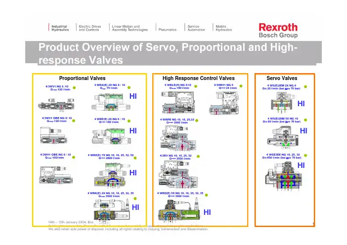
14th –15th January 2004, Bosch Rexroth in China4 WRD(E) 5X NG 10, 16, 25, 32, 35Q max 3000 l/min 4/3RV NG 10, 16, 25, 32Q max 3500 l/min4 WRLE(H) NG 6/10Q max 180 l/min 4 WRA(E) 2X NG 6 / 10Q max 75 l/min 4 WRE(E) 2X NG6 / 10Q max 180 l/min 4 WRZ(E) 7X NG 10, 16, 25, 32, 52Q max 2800 l/min 4 WRK(E) 2X NG 10, 16, 25, 32, 35Q max 3000 l/min Proportional ValvesHigh Response Control Valves 4 WS(E)2EM 5X NG 10Q N 90 l/min (bei Δpv 70 bar)4 WSE3EE NG 16, 25, 32Q N 850 l/min (bei Δpv 70 bar)4 WS(E)2EM 2X NG 6Q N 20 l/min (bei Δpv 70 bar)Servo Valves 4 WRPE NG 10, 16, 25,32Q max 3500 l/min 4/3HRV1 NG 6Q max 24 l/min 4/3WV1 NG 6 /10Q max 120 l/min 4/3WV1 OBE NG 6/ 10Q max 120 l/min 4/3WV1 OBE NG 6 / 10Q max 100l/min HIHIHIHI HIHI HI HI14th–15th January 2004, Bosch Rexroth in China14th–15th January 2004, Bosch Rexroth in China14th –15th January 2004, Bosch Rexroth in China开环比例液压系统)传统的结构形式: 4WRA4精度较低, 响应较慢4滞环:≤5% ;灵敏度: ≤0.5% ;反向域: ≤ 1 %4相频特性(-900, 50%输入信号):10 ~ 25Hz14th –15th January 2004, Bosch Rexroth in China4WRE …注意:不同系列的比例伺服阀的放大器(尤其外置放大器),其电气参数不同!即外置放大器一般不可更换!不同系列的比例伺服阀的安装尺寸有的相同,有的不同,需进行一下核对!14th–15th January 2004, Bosch Rexroth in China14th –15th January 2004, Bosch Rexroth in China开环比例液压系统先导式比例方向阀:4WRZ电比例控制多路阀的仿制品 精度较低, 响应较慢滞环:≤6% ;Proportional Directional Valve 4WRZE-7XFeatures 4WRZE-7X...Piloted Proportional Valve with and without O n B oard E lectronicsPilot pressure controlled by a pressure control valve D3High reliability and simple operationAt loss of electrical power or cable brake, main spool is positioned in stroke center positionmax. allowable contamination level of the fluid is class 9 to NAS 1638, or 18/15 to ISO 440614th–15th January 2004, Bosch Rexroth in China14th–15th January 2004, Bosch Rexroth in China14th–15th January 2004, Bosch Rexroth in China14th –15th January 2004, Bosch Rexroth in China开环比例液压系统DBETE…–精度一般, 响应较慢–Q max =2 l/min.–滞环:≤±1.5 %–重复精度: ≤±2 %–线性度:最高压力的±3.5 %–开关时间:30~150ms14th –15th January 2004, Bosch Rexroth in China直控式,带反馈;DBETRE …(PV1-DBV …)DBETRE…–精度较高, 响应很快–Q max =1 l/min.–滞环:≤0.2 %–温漂: ≤1 % ,当ΔT=400C–开关时间:10ms (10%)~30ms(100%)14th –15th January 2004, Bosch Rexroth in China先导式,不带反馈;(Z)DBE(E) (6)(Z )DBE (E )…–精度一般, 响应较快–Q max =30 l/min.–滞环:≤ 1.5 %–重复精度:≤ 2 %–线性度:±3.5 %–开关时间:50ms(10%)~80ms (90%)14th –15th January 2004, Bosch Rexroth in China先导式,不带反馈;DB …6?(PV2-DBV …)DB…–精度一般, 响应较慢–Q max =40 l/min.–滞环:≤ 4 %–制造公差: ≤10 %–开关时间:200ms (100%+)~250ms (100%—)HI 14th–15th January 2004, Bosch Rexroth in China14th –15th January 2004, Bosch Rexroth in China先导式,不带反馈;DBEM(E)…16;25DBEM(E)…–精度一般, 响应较慢–Q max =600 l/min.–滞环:≤±1.5 %–线性度:≤±3.5 %–重复精度:≤±2 %–制造公差: ≤±2.5 %–开关时间:150ms (100%+)~150ms (100%—)先导式,带反馈;DB (10)DB…DBV –精度较高, 响应较快–Q max=。
力士乐比例伺服阀的工作原理及应用领域

力士乐比例伺服阀的工作原理及应用领域力士乐比例伺服阀的工作原理及应用领域一、力士乐比例伺服阀的工作原理力士乐伺服阀是一种控制流量的阀门 ,通过电子控制技术对阀门的位置和开度进行控制,实现准确的流量控制。
其主要工作原理是将电子信号转换为机械运动,通过机械运动控制流体的流动,从而实现对流量的控制。
伺服阀通常由一一个由电磁铁驱动的活塞组成,当电流通过电磁铁时,活塞会向一个方向移动,从而改变阀广]的位置和开度。
这种控制方式比传统的机械控制方式更加精确。
伺服阀还可以通过反馈回路控制阀[ ]的位置和开度,从而实现更为准确的流量控制。
二、力士乐伺服阀的应用领域由于伺服阀具有精准的流量控制能力,它在许多领域都有广泛应用。
以下是几个应用领域的例子:1. 伺服阀通常被用来控制液压缸和液压马达的运动,以及调节飞机的姿态和高度。
2.机器人控制:在机器人控制领域,伺服阀可以用来控制机器人的肢体运动,并精确控制机器人的位置和速度。
3.工厂自动化:在工厂自动化领域,伺服阀可以控制流体的流量,从而实现精确的工业过程控制。
4. 伺服阀工业:在汽车工业中,伺服阀可以控制制动器的压力,从而调节车辆制动的力度和灵敏度。
总之,伺服阀在许多领域都有广泛应用,它可以精确地控制流量,从而实现更为准确的流体控制。
关于力士乐伺服阀的作用,伺服阀这个很多人还不知道,今天来为大家解答以上的问题,现在让我们一起来看看吧!1、伺服阀和比例阀,都是通过调节输入的电信号模拟量,从而无极调节液压阀的输出量,例如压力,流量,向。
2、( 伺服阀也有脉宽调制的输入方式)。
3、但这两种阀的结构不同。
4、伺服阀依靠调节电信号,控制力矩马达的动作 ,使衔铁产生偏转,带动前置阀动作,前置阀的控制油进入主阀,推动阀芯动作。
5、比例阀是调节电信号,使衔铁产生位移,带动先导阀芯动作,产生的控制油再去推动主阀芯。
6、伺服阀的结构非常复杂,前置阀有喷嘴挡板式,有射流管式,主阀芯还带有位移反馈。
力士乐伺服阀放大器说明书

电气放大器类型 VT-VRRA1-527-2X/V0/K40-AGC-2STV组件系列 2XRC 30043/02.12替代对象:11.02目录内容 页码特点1订货代码,附件 2前板2带插脚分配的电路图 3技术数据 4调试 5单元尺寸6项目规划/维护说明/附加信息6特点– 适用于控制带有双增益的特性曲线的先导式方向控制阀– 双增益的阀特性曲线的线性化– 单杆液压缸的面积比调节– 用于安装在 19 英寸机架上的欧洲格式的模拟放大器– 可控输出级– 选通输入– 防短路输出– 调节可能性 – 零位阀– 实际值电缆的电缆断连检测– 带有 PID 调节的位置控制– 较小信号范围内的增益注意:图片所示的是示例配置。
实际交付的产品与图片会有所差异。
1/6订货代码,附件前板首选类型放大器类型材料编号用于带电气位置反馈和弯折的特性曲线的先导式方向控制阀VT-VRRA1-527-20/V0/K40-AGC-2STV08114050684WRL 10...35 V/V1...P-3X...4WRL 10...25 V/V1...P-3X...-750液压组件:用于具有电气反馈的阀 = R阀类型:方向控制阀 = R控制模拟= A选件K40-AGC-2STV = 在40%位置处双增益的先导式方向控制阀客户定制型号 V0 =标准样本型号2X =组件系列 20 至 29(20 至 29:技术数据和插脚分配不变)以下类型的序列号:527 =先导控制阀规格 6单杆液压缸的面积比调节较小信号范围内的增益粗调节精确调节VT-V RR A 15272X V0K40-AGC-2STV配套的板卡插槽:– 开放式板卡插槽 VT 3002-1-2X/32F (请参阅样本 29928)。
仅限用于控制柜安装!0带插脚分配的电路图控制零位控制零位电位计电源启用信号输入错误技术数据(有关这些参数之外的应用,请务必向我们咨询!)在 z2 – b2 处的电源电压 UB 公称电压 24 V =,电池电压 21…40 V,整流后的交流电压 Ueff= 21...28 V(单相,全波整流器)单独在 z2 – b2 处的滤波电容器建议:电容模块 VT 11110(请参阅样本 30750)(只有当 UB的波动值 > 10 % 时方可使用)阀线圈最大值 A/VA 2.7/40(先导控制阀规格 6)最大电流消耗 A 1.7电流消耗可能会随 最小 UB和到控制线圈的极限电缆长度增加功耗(典型值) W37输入信号(控制值)b20:0...±10 Vz20:0...±10 V }差动放大器(Ri= 100 kΩ)信号源b32,z32(10 mA)的电位计 10 kΩ,电源 ±10 V 或外部信号源启用输出级在 z16,U = 8.5...40 V,Ri= 100 kΩ,前板上的 LED(绿色)亮起位置传感器电源b30:–15 Vz30:+15 V先导控制阀实际值信号b22:0...±10 V实际值参考位b24主级实际值信号b26:0...±10 V实际值参考位b28线圈输出b6 – b8 I最大定时电流控制器2.7 A放大器与阀之间的电缆长度线圈电缆: 20 至 20 m 1.5 mm220 至 60 m 2.5 mm2位置传感器: 4 x 0.5 mm2(已屏蔽)主要特点 实际值电缆的电缆断连防护,带有 PID 调节的位置控制,脉冲输出级,具有较短启动时间的快速通电和快速断电,防短路输出,双增益流量特性曲线的线性化调节 零电位通过微调电位计 ±5 % 进行调节,单杆液压缸的面积比调节,较小信号范围内的增益LED 显示 绿色: 启用,黄色: 电缆断连实际值,红色: 欠电压(UB过低)错误消息– 电缆断连实际值– UB 过低– ±15 V 稳定z22:集电极开路输出到 +UB 最大 100 mA;无错误:+UB电路板格式 mm(100 x 160 x 大约 35)/(W x L x H)使用前板为 7 TE 的欧洲格式插入式连接连接器 DIN 41612 – F32环境温度 °C0...+70存储温度范围 °C–20...+70重量 m0.39 kg注意:电源零位 b2 和控制零位 b12 或 b14 或 z28 必须单独通向中心接地(零点)。
力士乐伺服阀机电工作原理

力士乐伺服阀机电工作原理
几天,小编一直有在关注与学习力士乐伺服电机相关知识,那么,力士乐伺服电机工作原理又是怎么样的呢?下面我们具体来看看伺服电机工作原理。
力士乐伺服电机工作原理
伺服电机本身具有调速性好、输出功率高、精度高、力矩波动小等特点,能够在封闭的环里面使用,广泛应用于机床、印刷设备、包装设备、纺织设备等领域,
力士乐伺服主要靠脉冲来定位,基本上可以这样理解,伺服电机接收到1个脉冲,就会旋转1个脉冲对
应的角度,从而实现位移,因为,伺服电机本身具备发出脉冲的功能,所以伺服电机每旋转一个角度,都会发出对应数量的脉冲。
这样,和伺服电机接受的脉冲形成了呼应,或者叫闭环,如此一来,系统就会知道发了多少脉冲给伺服电机,同时又收了多少脉冲回来,这样,就能够很精确的控制电机的转动,从而实现精确的定位,可以
达到0.001mm。
以上内容是关于力士乐伺服电机工作原理的介绍,希望对大家的使用有进一步的认识和了解。
通过伺服电机工作原理,能够让我们对伺服电机是如何运行的有更深一步的了解。
德国力士乐比例换向阀工作原理2011
德国力士乐比例换向阀工作原理2011-1-14 来源:上海颖哲工业自动化设备有限公司第五营业部>>进入该公司展台德国力士乐比例换向阀工作原理,REXROTH比例换向阀作用,力士乐换向阀应用德国REXROTH比例换向阀是一种中高压整体式两路换向阀。
可按客户要求在阀上设溢流阀、过载阀、单向阀、补油阀等。
溢流阀可调节系统压力、过载阀控制单个油腔工作压力,单向阀防止油液倒流,换向阀滑阀机能有A、O、Y、P等,可任意组合。
换向手柄有两种安装形式,便于不同方向的操作。
该阀采用并联油路,设计有压力输出口与其它液压元件相接提供动力源。
经过特殊设计的密封方式,使阀的密封性能卓越。
该阀泛用于叉车、环卫车辆、小型装载机等工程机械的液压系统。
液压换向阀,由左右驱动阀组成,驱动阀包括驱动阀阀体和阀芯,其特征是:所述驱动阀阀体上设有过载保护阀,过载保护阀与阀体的进出油口连接,所述过载保护阀包括主阀体、副阀体、阀针和单向阀芯,所述主阀体后端螺接有副阀体,所述副阀体内腔置有阀针,阀针后端套接复位弹簧,锥形阀针与副阀体前端的油孔触接,所述单向阀芯前端设有圆孔,圆孔与节流阀芯滑动配合,所述中心设有节流孔的节流阀芯后端设有弹簧,所述副阀体前端与单向阀芯内腔之间形成卸压腔。
有益效果:实现了微动效果;增加过载保护阀,使工作系统传过来的瞬时高压在系统的溢流阀卸荷之前开启,去除峰值压力,有效保护了液压件及结构件免受到破坏性冲击,换向阀是管路流体输送系统中控制部件,它是用来改变通路断面和介质流动方向,具有导流、截止、调节、节流、止回、分流或溢流卸压等功能。
REXROTH比例换向阀原理主要用来控制流体。
例1个活塞向1个方向移动。
要向1端充流体,另1端排流体,进的1端是高压流体,出的1端回到油箱。
这1个动作要求进端阀打开,排(回)流阀关闭,另1端进端阀关闭,打开排(回)流阀关闭。
活塞材能向1个方向移动。
目前现成产品有2位3通,2位4通,3位5通等。
力士乐比例减压阀中文说明书

力士乐比例减压阀中文说明书力士乐比例减压阀功能:通过比例电磁铁设置A或B中的压力。
压力的大小取决于电流。
线圈(5、6)断电后,控制阀芯(2)将通过压缩弹.簧(8)保持在中心位置。
油口A和B连接到T,以便液压油可以不受阻挡地流入油箱。
通过为比例电磁铁(例如线圈“a"(5))通电,压力测量阀芯(3)和控制阀芯(2)将向右移动。
这样将通过具有渐进流体特性的节流横截面,打开从P到B及从A到T的连接。
在通道B中形成的压力通过压力测量阀芯(4)的表面作用于控制阀芯,抵抗线圈磁力。
压力测量阀芯(4)受线圈“b”支撑。
如果压力超过线圈“a”上设置的值,将逆线圈磁力方向回推控制阀芯(2),并建立B与T的连接,直到重新达到调定压力。
压力与线圈电流成比例。
当线圈关闭时,控制阀芯(2)在压缩弹簧(8)的作用下返回到中心位置。
可选手动应急操作元件(9、10)可在线圈不通电的情况下移动控制阀芯(2)。
德国REXROTH力士乐比例减压阀特征用于控制压力和流向的直动式比例阀通过带有中心螺纹和可拆卸线圈的比例电磁铁进行操纵用于底板安装:孔图按ISo4401手动应急操作,可选弹簧定中的控制滑板带集成电子元件(OBE)的型号3DREPE带外部电子元件的型号3DREP型号DRSandZDRS比例减压阀,先导式,有直流马达操作规格6安装面按ISO4401用于降低系统压的阀,有溢流功能直流马达操作力士乐减压阀/力士乐比例减压阀底板安装作为叠加阀型号3DRE(M)和3DRE(M)E比例减压阀,先导式规格10和16安装面按DIN24340A型和ISO4401用于降低系统压力的阀比例电磁铁操作底板安装用于3DREEand3DREME的集成电控器(OBE)型号DRE比例减压阀,先导式规格6和10规格6:安装面按ISO4401规格10:安装面按ISO5781-AG-06-2-A用于降低系统压力的阀比例电磁铁操作通过电磁铁电枢位置进行调节DREBE型的集成电控器(OBE)型号DRE(M)和DRE(M)E比例减压阀,先导式规格10至32安装面按DIN24340D型用于降低系统压力的阀比例电磁铁操作底板安装线性压力/指令值特性曲线用于DREM和DREME型的ZUi大减压功能可选单向阀,在A和B油口之间集成电控器(OBE),用于DREE和DREME 型号(Z)DREandZDREE10比例减压阀,先导式规格6和10安装面按DIN24340A型和ISO4401力士乐比例减压阀中文说明书。
4WRZE力士乐比例阀样本
4WRZE力士乐比例阀样本
一、结构
二、工作原理
4WRZE力士乐比例阀的工作原理是通过电磁线圈产生的磁场作用于阀芯,使阀芯在阀体内做上下运动,从而调节阀芯开口大小,进而调节流体流量。
电磁线圈接收到控制信号时,通过电流变化而改变磁场强度,从而实现对阀芯位置的精确控制。
三、特点
1.高精度:4WRZE力士乐比例阀采用先进的比例电磁阀技术,具有调节精度高的特点,可满足各种流量调节的要求。
2.双向控制:4WRZE力士乐比例阀可实现双向控制,能准确调节正反向流体的流量,并且切换迅速,无泄漏。
3.快速响应:4WRZE力士乐比例阀的电磁阀响应时间短,能快速调节流量,适应高速流体控制的需求。
4.高可靠性:4WRZE力士乐比例阀采用高质量的材料和先进工艺,具有耐腐蚀、耐高温、耐压等特点,保证了阀门在恶劣环境下的长期稳定运行。
5.节能环保:4WRZE力士乐比例阀能通过精确调节流量来实现能源的高效利用,降低系统能耗,并且采用无渗漏设计,避免了浪费和对环境的污染。
四、适用范围。
4WRZE力士乐比例阀样本
B → T:qV /2 A → T:qV B → T:堵塞
A → T:qV
注意:符号为 W6-,W8-,W9-,W6A 时,A → T 和 B → T 的连接距离在切换位置 "0" 的各公称剖面的 2 % 以下。
4/28 Bosch Rexroth AG Hydraulics
.WRZ;.WRZE;.WRH RC 29115/08.13
= 无代码 =E
= ET =T
RC 29115/08.13 .WRZ;.WRZE;.WRH
Hydraulics Bosch Rexroth AG
3/28
*
M = V = 无代码 = D3 1)=
A1 = F1 = 无代码 =
K4 1, 4)=
K31 1, 4)=
1)不适用于型号 4WRH 2)适用于型号 "J" → "N",不适用于 "N9"
不带电气位置反馈,不带/带集成电子 RC 29115/08.13 1/28
元件(OBE)的先导式二位四通,
替代对象:10.05
三位四通和二位五通,
三位五通比例方向阀
型号 .WRZ…,.WRZE… 和 .WRH…
规格 10 至 52 组件系列 7X 最大工作压力 350 bar 最大流量 2800 l/min
带液压操作
型号 4WRH…-7X./… 和 型号 4WRH 52…-7XF/…
AB
a
a 0b
b
X
PT
X
型号 5WRH 52…-7X. AB
a
a 0b
b
X
RPT
X
X = 外部 Y = 外部
X = 外部 Y = 外部
rexroth比例阀技术参数
一、rexroth比例阀的定义和功能rexroth比例阀是一种用于控制液压系统流量的重要组成部分。
它能够根据控制信号精确地调节流体的流量比例,从而实现对液压执行元件的精准控制。
rexroth比例阀广泛应用于工业生产和机械设备领域,能够提高系统的控制精度和效率。
二、rexroth比例阀的技术参数1. 额定流量rexroth比例阀的额定流量是指在额定工作条件下,阀芯的最大流量。
通常以升/分钟或立方米/小时为单位进行标识。
2. 控制精度控制精度是指rexroth比例阀在工作过程中实际输出流量与设定值之间的偏差范围。
一般以百分比来表示,控制精度越高,说明阀门能够更精确地控制流量。
3. 压力损失rexroth比例阀在工作时会产生一定的压力损失,这会影响整个液压系统的性能。
压力损失通常以巴或帕ascal为单位进行标识,压力损失越小,阀门的效率越高。
4. 工作温度范围rexroth比例阀能够在一定的温度范围内正常工作,超出规定的温度范围会影响阀门的性能和寿命。
工作温度范围通常以摄氏度或华氏度来表示。
5. 控制信号rexroth比例阀通常需要外部控制信号来调节流量,常见的控制信号有电压、电流和压力信号等。
控制信号的稳定性和精度对阀门的工作效果具有重要影哥。
6. 阻尼特性rexroth比例阀在流量调节过程中的阻尼特性对于阀门的稳定性和工作效率具有重要影响。
阻尼特性好的阀门能够更精确地控制流量,避免振荡和波动。
7. 使用寿命rexroth比例阀的使用寿命是指在规定的工作条件下,阀门能够正常工作的时间。
使用寿命通常以工作小时或工作循环次数来表示,是衡量阀门质量好坏的重要指标。
8. 安全防护rexroth比例阀在工作时需要具备一定的安全防护措施,以防止意外事故的发生。
包括过载保护、漏电保护、过压保护等。
三、rexroth比例阀的应用领域rexroth比例阀广泛应用于汽车、机械设备、航空航天、船舶、冶金、化工等领域。
在这些领域,rexroth比例阀能够实现对液压系统的精确控制,提高系统性能和效率。
力士乐REXROTH伺服参数设置
力士乐REXROTH伺服参数设置文中简述了力世乐ECODRIVE03 伺服驱动系统通过并行接口进行位置块(组)操作模式(position block mode)的控制原理,并例举了与伺服驱动相关的故障及其解决方法。
数控机床控制中西门子、法那科伺服驱动系统应用较为普遍,而力世乐ECODRIVE03 伺服系统亦广泛地应用于机械制造、印刷造纸业、食品包装及集装总装等领域。
拥有FWA-ECODR3-SMT-02VS-MS 等系列硬件的ECODRIVE03 伺服系统通过串行、模拟、并行接口,及对系统标准参数(S 型参数)生产参数(P 型参数)的设置,可完成扭矩控制、速度控制、位置控制、插补控制、点动、位置块(组)及步进电机等模式的操作。
且系统带有测量、驱动、暂停、模拟输入/输出、数字输入/输出等多种基本功能并拥有完备的诊断功能。
下面介绍力世乐伺服系统的位置块(组)操作模式的控制原理。
1 位置块(组)操作模式的控制原理1.1 概述位置块(组)操作模式的控制原理位置块(组)操作模式是伺服系统以设定的速度、加速度等参数驱动电机运行到已在程序中预设的目标值的位置控制。
系统根据所处理的不同工艺过程(加工区域)最多可以设置64 个位置块(组)。
应用位置块(组)操作模式时,首先要对操作首要模式参数S-0-0032 进行设置,如设置为0000 0000 0011 х011 时,是通过编码器1 接口进行位置控制。
其中第3 位,bit3=0时代表位移滞后控制,bit3=1 时为无滞后控制;同时要将第二操作模式1 设置为点动模式,即设置参数S-0-0033 为1100 0000 0001 1011。
系统中与之相关的参数为:P-0-4006:加工块的目标位置值P-0-4007:加工块的速度值P-0-4008:加工块的加速度值P-0-4009:加工块的加加速度极值。
当设定为“0"时,极限值不起作用。
无论是绝对值还是相对值控制方式,P-0-4006、P-0-4007、P-0-4008、P-0-4009都有效,且每个参数都可最多设置为64 个数据,分别对应于0-63 数据块(组)的各个值。