
orange-橙的电子-汽车胎压监测系统-TPMS-P409-Manual-手册-说明书
Manual for Tire Pressure Monitoring Systems, TPMS
Orange TPMS 無線胎壓監測系統
無線胎壓監測系統(TPMS)提高駕車時的安全。一旦安裝在您的車輛,系統會自動監測您輪胎的 實際壓力和溫度。當任何輪胎的壓力或溫度出現異常時,監測系統會主動警示,並顯示出數字提醒 使用者。該系統輔助的安全,可以延長輪胎壽命和降低燃油消耗。
胎壓過低警告值設定................................................................................................................ 8 胎壓過高警告值設定................................................................................................................ 8 胎溫過高警告值設定................................................................................................................ 9 異常警告說明 .......................................................................................................................... 9
系統安裝及使用 無線胎壓監測系統要求要有正確的安裝方法並經由合格操作人員依照安裝手冊之步驟進行系統安 裝,該系統才能正確動作並提供保固。因安裝不當或拆卸而損壞感測器者,將不受產品保固。本系 統適用於轎車,越野車和吉普車的輪胎使用,最大可量測壓力為 74 psi (表壓力)。 *強烈建議每年定期更換或檢查”輪胎氣門嘴”,避免輪胎氣門嘴有漏氣等現象發生。
產品警告 本系統是利用感測器量測輪胎內的壓力及溫度並以無線電訊號傳輸,在正常運作過程中,監測器會 以綠色數值來表示接收到正常的輪胎壓力或溫度,當系統中的任一個或多個感測器偵測到輪胎處於 異常之胎壓或胎溫時,感測器會立即傳送警告訊號至車內的無線胎壓監測系統,當監測器收到輪胎 有異常的訊號後,會立即發出”嗶”聲警告並同時以紅色數字顯示通知駕駛者需立即檢查及修復輪 胎,以避免因輪胎胎壓不足或溫度過高之類問題而造成意外發生。
警告 本系統是無線傳輸訊號,因此在某些特殊環境狀況下有該系統可能會因為干擾因素或錯誤操 作方法或不當的安裝方法致使無線訊號減弱或收不到訊號之狀況發生,若監測器持續 20 分鐘接收 不到某一輪胎之訊號時,該輪胎的顯示數值會顯示”E2”。此時應將汽車遠離目前位置(可能附近有 強烈的無線訊號干擾)或盡速前往指定的輪胎保修廠檢查輪胎內的感測器是否有故障發生或輪胎內 感測器之電池耗盡(電池可能因為經常有異常狀況出現,而需要連續發射無線電波訊號警告駕駛 人,使得電池壽命比正常使用年限短)。若系統持續 20 分鐘以上接收不到任何一輪的訊號,則可能 為監測器故障,此時四輪輪胎的顯示數值皆會顯示”E1”,請速裝汽車遠離目前位置(可能附近有強 烈的無線訊號干擾)或將監測器送回經銷商檢修。
系統警告方式 當警告燈號及嗶聲響起時,應該減低速度並尋找安全停靠位置檢查輪胎並立即到就近合格之輪胎修 護廠進行修復。 胎壓過低警告表示輪胎胎壓之壓力已經洩漏至安全胎壓值以下。 溫度過高警告表示輪胎溫度已經高過安全標準值。 電瓶電壓過低警告表示電瓶電壓已經低於 11.0 伏特。
化學物品使用 密封膠或特殊輪胎充填化學物質可能導致胎壓監測系統的誤動作或影響感測器的動作。
附錄 1 ........................................................................................... 16 附錄 2 ........................................................................................... 16 系統保固 ....................................................................................... 17
2/17
Manual for Tire Pressure Monitoring Systems, TPMS
電池使用壽命 感測器儲存溫度 感測器工作溫度 感測器工作濕度 感測器工作頻率 輪胎壓力監測範圍 胎壓讀取誤差值 溫度讀取誤差值 感測器功率 電池容量 感測器重量
操作電壓 操作電流 監測器儲存溫度 監測器工作溫度
系統安裝
無線胎壓監測器系統分成兩個部份,分別說明安裝方法如下: 1. 無線接收顯示器安裝於車內 2. 無線胎壓感測發射器安裝於輪胎內 *強烈建議先安裝無線接收顯示器後,再安裝 4 組無線胎壓感測發射器 注意:保固範圍除了"監測器"和"無線胎壓感測器"以外,其餘配件皆屬消耗品,在變更輪胎位 置、更變輪胎及更換無線胎壓感測器”,所有輪胎氣嘴和氣嘴螺絲將要更換成新的”輪胎氣嘴”和”氣 嘴螺絲”。(當安裝無線胎壓感測器、新輪胎氣嘴、氣嘴螺絲時將必須使用。)
系統設定輪胎更換位置方式 .......................................................... 10
Mode 1:前輪和後輪互換..................................................................................................... 11 Mode 2:輪胎對角線互換..................................................................................................... 12 Mode 3:前輪對角線更換至後輪,後輪平行更換至前輪...................................................... 13 Mode 4:任意更換輪胎位置 ................................................................................................. 14
無線胎壓監測系統規格
胎壓感測發射器規格表 正常狀況下超過 7 年 -40oC to 125oC -30oC to 120oC 最大 95% 433.92MHz 0~74 psi 正常操作狀態下± 1psi ± 4oC (一般正常環境下) 最大 5 dBm 3.0V 32g ±3 g
接收顯示器規格表 直流 12V < 200mA -30oC to 105oC -30oC to 85oC
合位置。 4. 安裝完畢後請移除接收顯示器上的保護貼。
汽車供電的點煙座 正極(紅色)
B ALeabharlann 天線(黑色)ACC (綠色)
負極(網線)
C
電源線
4/17
Manual for Tire Pressure Monitoring Systems, TPMS
無線胎壓感測發射器安裝
D E
3/17
Manual for Tire Pressure Monitoring Systems, TPMS
B
A F
D
C
E
H
無線胎壓顯示器安裝
1. 將電源線(C)的一端插入無線胎壓顯示器(A)的下方的電源接孔處。 2. 將電源線(C)的一端點煙器接頭插入汽車的點煙座內。
( 或是切斷點煙器接頭,將 ACC、正極、負極電源線接入保險絲盒,白色的線空接即可) 注意:將 ACC、正極、負極電源線接入保險絲盒,顯示器可以全時接收到訊號,但是只有在 ACC 啟動後 LED 燈才會顯示,當 ACC 關閉時 LED 燈就會熄滅。 3. 安裝接收顯示器於汽車儀表板適合位置 - 將(B)2 個分別黏貼在接收顯示器(A)背面及儀表板中適
無線胎壓監測系統配件清單
NO.
產品單元名稱
A 監測器(內建無線接收電路)
B 魔鬼氈
C 電源連接線(點煙器電源接頭)
D 無線胎壓感測器
E 輪胎氣嘴
F 氣嘴鎖附螺絲(耐落處理螺絲)
G 系統操作手冊
H 磁性擋風玻璃吸附支架(依實物為主)
數量 1 2 1 4 4 4 1 1
警告 本產品之電源連接線不得用於其它產品,亦不支援 USB 介面,請勿連接至任何 USB 裝置, 以免發生故障。
警告
FCC 警告 此系統已經遵守美國 FCC 法規第 15 條標準要求,但操作使用時仍需符合下列注意事項: (1) 該產品可能因為其他有害的干擾導致系統無法作動。 (2) 該系統不正常的操作可能導致系統失敗。 該系統經過儀器的測試並遵守數位 Class B 的限制,根據 FCC 第 15 條規定,這些限制的設計是 提供有意義的保護以防止干擾訊號源在住宅區出現。這種設備將會產生無線射頻訊號,如果未能依 照安裝及正確使用會導致產生一些訊號源干擾無線通訊。然而,縱使正確安裝也無法完全確保不會 有干擾產生。 如果該產品會干擾到無線收音機或電視機的收訊時,可以由使用者自行決定是否關閉該產品。使用 者也可以自行調整正確頻率解決問題,可能方法如下: z 重新調整天線 z 增加設備與該系統的距離 z 變更接收器的位置與連接方式 警告 任何的自行修改或變更系統本體將無法保證操作者的權益繼續受到保護。
Manual for Tire Pressure Monitoring Systems, TPMS
為了確保正確的操作和服務,請先閱讀手冊上的說明,然後再進行安裝和操作
Orange TPMS 無線胎壓監測系統操作手冊
i80 PAD汽车智能诊断平台 用户手册说明书

4. 设置
点击左上角的
图标,再点击【设置】,打开设置界面,可设置语言、单位等。
4.1 语言选择
选择语言,在右侧众多语言选项中选择需要的语言打勾即可。
国内销售的 i80 PAD 只支持简体中文。
12
I80 PAD
4.2 单位:选择计量单位,公制或英制 13
I80 PAD
5. 诊断报告 “诊断报告”用于查看已保存的文件,比如诊断过程中数据流或故障码报告, 或视频回放,还可查看测试过的车型。
不可拉扯线束中间段,插接线束时先查看接口的对应方向平着插接, 不可斜着插接以免损坏端子。
11
I80 PAD
(3)进行一些特殊功能的测试时,操作人员务必按照操作提示说明进行操作。 对车上则 需要严格满足要求,如有的车型“特殊功能”需要满足的条件有: 引擎水温 80℃/105℃,关闭大灯、空调等负荷,加速踏板在松开位置等。 (4)由于国内车型配备的电控系统比较杂乱,如遇到无法测试或测试数据 不对的情况,考虑所选菜单和被测电控系统是否对应,可查找到该车 ECU, 通过 ECU 标贴上的型号进行菜单选择。 (5)在 i80 PAD 测试菜单中未找到所测车型或电控系统时,可能未进行 软件升级或向公司技术服务部咨询。 (6)禁止使用非朗仁科技公司配套的线束进行连接测试,以免造成不必要的损失。 (7)在 i80 PAD 与车辆通讯中,禁止直接关机。应先将任务取消后 再返到主界面进行关机。
6. 一键升级激活后,i80 PAD 设备升级只需进入一键升级, 点击升级即可,如下图所示。
14
I80 PAD
7. 朗仁云 所有使用 i80 PAD 的汽车维修技师可非常方便的查询我司放在云服务平台 的维修资料,并且可结合汽车诊断出来的结果去查询使用,同时还可以访问 大量维修及诊断技巧以及车辆维修方案的线上数据库。
合微hw004胎压监测使用说明

合微hw004胎压监测使用说明合微HW004胎压监测使用说明一、产品概述合微HW004胎压监测系统是一款专用于汽车胎压检测的设备。
它通过安装在车辆轮胎上的传感器,实时监测胎压和温度,并将数据传输到接收器,以便驾驶员随时了解轮胎的状态。
本文将详细介绍HW004胎压监测系统的使用方法和注意事项。
二、产品组成HW004胎压监测系统由以下几部分组成:1. 传感器:每个轮胎都需要安装一个传感器,用于检测轮胎的胎压和温度。
2. 接收器:接收来自传感器的数据,并将其显示在仪表盘上。
3. 显示屏:显示当前各个轮胎的胎压和温度。
三、安装步骤1. 安装传感器:a. 将车辆停在平坦的地面上,并拉起手刹。
b. 使用专用工具拧下每个轮子上的气门帽。
c. 将传感器插入气门孔中,并用适当扭矩固定。
d. 重复以上步骤,直到所有轮子上都安装了传感器。
2. 安装接收器:a. 找到车辆的OBD-II接口,通常位于驾驶员座椅下方。
b. 将接收器插入OBD-II接口,并确保连接牢固。
3. 安装显示屏:a. 找到合适的位置,将显示屏固定在仪表盘上。
b. 使用提供的支架或双面胶带将显示屏固定在位置上。
四、使用方法1. 开启系统:a. 启动车辆,并等待几秒钟,直到系统自动检测到传感器并开始工作。
b. 在显示屏上,您将看到各个轮胎的胎压和温度数据。
2. 胎压警报:a. 当任何一个轮胎的胎压低于或高于设定值时,系统会发出警报音和闪烁提示。
b. 驾驶员应立即停车检查轮胎,并根据情况采取相应的措施。
3. 胎压校准:a. 如果更换了轮胎或调整了气压,请进行胎压校准以确保准确性。
b. 在显示屏上选择“设置”菜单,然后选择“校准”选项。
按照提示进行操作完成校准。
4. 数据保存:a. 系统将自动保存最近的胎压和温度数据,以便您随时查看历史记录。
b. 在显示屏上选择“历史”菜单,然后选择相应的选项来查看特定时间段内的数据。
五、注意事项1. 定期检查传感器和接收器的电池电量,并及时更换。
橙色电子(Orange Amplifiers)罗克勒30(Rockerverb 30)产品说明书

Orange Amplifiers Glenhaven Avenue Borehamwood Hertfordshire WD6 1AY ENGLAND Tel: +44 20 8905 2828Fax: +44 20 8905 2868*************Orange USA2065 Peachtree Industrial Ct.Suite 208Atlanta, GA 30341USA Tel: 1-404-303-8196Fax: 1-404-303-7176******************Rockerverb 30Owners ManualRocker 30 Owners ManualThank you for choosing Orange. You are now a member of the ‘Legendary British Guitar Amplifier’ owners club!Since 1968, when the company was founded, Orange has been a pioneering force in the guitar amplification industry. Today, with a team of the world’s finest amplifier engineers, Orange continues to push back the boundaries of conventional tube amplifier design.Our commitment to craftsmanship and quality control has allowed our amplifiers to stand the test of time, giving their owners as much pleasure now, as the day they were bought. To maintain this level of excellence, each Orange amplifier is put through many rigorous test procedures before leaving the factory.The warmth, tonal quality and rich harmonics generated by a valve amplifier cannot be reproduced by ‘artificial’ means. Many guitarists have reached the same conclusion: neither the transistor nor microchip is a suitable alternative to valve technology.This booklet contains valuable technical and safety information Please take the time to read this manual as the information may enhance the sound and performance of your amplifier.We are confident that you will be delighted with your new purchase and that it will provide you with many years of enjoyment.Introduction Front and Rear Panel Explanations Using Your Amplifier Technical Specifications .........................................................................................................................................................................................1...............................................................................................................................................2..........................................................................................................................................................................3. (3)ContentsFront PanelRear Panel1. Power/Standby Switch Up position - amplifier is offMiddle position - amplifier is on standby Down position - amplifier is on2. Channel Switch Switches between the Natural and Dirty channels3. Power Indicator Lamp4. Dirty Volume Control Controls output volume level for the Dirty channel5. Dirty Hi Control Controls treble frequency levels for the Dirty channel6. Dirty Mid Control Controls middle frequency levels for the Dirty channel7. Dirty Low Control Controls bass frequency levels for the Dirty channel8. Dirty Gain Control Overdrive/Distortion level for the Dirty channelThe Gain works from left to right increasing in saturation as the control is turned clockwise.9. Natural Volume Control Controls output volume for this channel. Please note this channel has no gain control andno EQ section. It is a ‘non-master volume’ channel.9 8 7 6 5 4 3 2 11. Channel Footswitch Socket Attaching an optional footswitch to this socket will allow you to remotely change channels.2. Speaker Outputs When using a single Orange 16 ohm speaker cabinet, (i.e. PPC412 or PPC212), attach it to the 16 ohm output socket on your amplifier.When using two Orange 16 ohm speaker cabinets attach each one to a separate 8 ohm output socket on your amplifier.When using a single 8 ohm cabinet attach it to either one of the two 8 ohm output sockets on your amplifier.WARNING: Never use two 8 ohm cabinets at the same time.When using the Rocker 30 combo with a 16 ohm extension speaker, disconnect the internal speaker from the 16 ohm socket and reconnect to one of the two 8 ohm sockets. Connect the extension speaker to the other 8 ohm socket.WARNING: Orange Rocker amplifiers should not be used with 4 ohm speakers.3. HT Fuse The high tension fuse, protects transformers and other circuitry from blowing in the event of an output valve shorting. Please refer to the Technical Specification section for fuse ratings.4. Mains Inlet Socket & Fuse Holder Tray This is where your mains lead plugs in. Also the mains fuse is located here. Please refer to the Technical Specification section for fuse ratings.5. Mains Voltage Switch Switches amp between 220V and 240V or 100V and 120V. This should be set to the mains electricity voltage used in the country where the amplifier is to be operated.Please ensure your amplifier is switched to the correct voltage for your country. If unsure please consult your dealer.5 4 3 2 2 2 1Using Your AmplifierIMPORTANT! Before connecting your amplifier to a power source, please check the following:1. Ensure your speaker cabinet is connected to the correct impedance speaker output socket, (see Rear Panel, item 2), using agood quality speaker cable. Do not use guitar leads. (Head models only. Combo models will have it’s speaker attached).2. Ensure that the voltage selector switch is set to the correct mains voltage, (see Rear Panel, item 5).When powering up your amplifier, switch to the ‘Standby’ position first and leave for two minutes before switching to the ‘On’ position. (This will maximise the life of your valves)..If you are unsure about any of the above points please consult your local Orange supplier.Using The ‘Natural’ ChannelThe Natural channel feeds your guitar straight into your amplifier’s power amp for pure, unaffected tone. Try this channel with different guitars to hear the tonal variations of each instrument. Increasing the gain will allow the power section to break up a little for natural distortion sounds.Using the ‘Dirty’ ChannelThe Dirty Channel has a three stage gain section, turning the gain control clockwise will gradually increase the saturation level from clean throughblues/crunch up to full rock sounds.Technical Specifications。
胎压监测(Tire pressure Monitoring) en

Passenger Car - ChassisTyre Pressure Monitor (TPM)Introduction trainingAs of 01/04TitelWithout words (1)System Components (2)System Functions (8)The most important in the end (17)Expensive and dangerous Wrong t y re pressure,Loss money?1 % higher fuel consumption 10 % shorter life2 %30 % shorter life4 % higher fuel consumption45 % shorter lifehigher fuel consumption1243System components:1. Wheel antennas X4 (A2/44 - 47)2. TPM control module (N88)3. Wheel sensors X4 (A69/1 - 4)4. Metal valvesThe tyre pressure monitor (TPM) is a system for permanently monitoring tyre inflation pressure. For this the tyre inflation pressure and tyre temperature are measured in the tyre at certain intervals and transmitted telemetrically to the TPM/[RDK] control module (N88) via an high frequence (HF) transmission link.The tyre pressure monitor system supports the driver when checking the correct tyre inflation pressure and thus serves active safety.Via the multifunction display (MFD/A1p13) in the instrument cluster (A1) the driver is informed about the current tyre inflation pressure or about the necessary corrections to the tyre inflation pressure and flat tyres.General information:1 countering nut2 spacer ring (2x45°)3 filling valve4 pin Ø 2 mm5 clamping screw a manufacture date b identification codeA69/1 wheel sensor TPM left front A69/2 wheel sensor TPM right front A69/3 wheel sensor TPM left rear A69/4 wheel sensor TPM right rear A69/5 wheel sensor TPM spare wheelAdvantages - Life and Economics- Tyre wear and fuel consumption are reduced by having the correct tyre pressure.The wheel sensors (A69/1-4) is mounted on the metal valve (not visible from outside) and measures the air pressure and temperature inside the tyre.The data transmitted by the wheel sensors are received by wheel specific antennas (A2/44-47). The TPM/[RDK] control module (N88) evaluates this data and determines the position of the transmitter from the field strengths measured at the wheel antennas. This ensures that the data can be correctly matched to the relevant wheel.The tyre pressure of each wheel adjusted and activated by the driver is stored in the TPM/[RDK] control module (N88) as a specified pressure to be monitored. The data evaluated by the TPM/[RDK] control module is shown in the multifunction display (MFD) of the instrument cluster (A1) in the form of messages relevant to the operation and function (N88). - Regular checking of tyre inflation pressure is simplified.- The tyre pressure monitor does not relieve the operator from a regular manual check of tyre inflation pressure (at least every 14 days). In the process the correct tyre inflation pressure must be adjusted by means of the table in the fuel filler flap. The tyre pressure monitor does not warn of a tyre inflation pressure which is incorrectly adjusted.Advantages - Safety- It takes place an early warning with fast pressure loss.- Tyre burst by excessive drumming work, caused by driving too fast with insufficient air pressure, are avoided.- The driver is requested to check the tyre inflation pressure.- There is a warning in good time in the event of a rapid pressure drop (pressure drop >0.2 bar).General functionAdvantages - ComfortThe t y re pressure control consists of the following components:The battery-operated wheel sensor is mounted within the tyres and measures the tyre pressure and temperature of wheel sensor electronics. Each wheel sensors possesses an identification (ID),with one transfers. The sensors work in 433MHz or 315 MHz(USA/ROW).1 clamping screw2 filling valve3 spacer ring4 countering nut5 capA69/1 wheel sensor TPM left front A69/2 wheel sensor TPM right front A69/3 wheel sensor TPM left rear A69/4 wheel sensor TPM right rearThe following are located in the housings: - Pressure sensor - Temperature sensor - Transmission stage- Lithium battery for internal voltage supply.Note:The TPM/RDK wheel sensors cannot be dismantled into its individual parts.Together with the filling valves (2) the left front tire pressure monitor wheel sensor (A69/1), right front tire pressure monitor wheel sensor (A69/2), left rear tire pressure monitor wheel sensor (A69/3) and right rear tire pressure monitor wheel sensor (A69/4) form a compact unit and are fitted in the rims like a screw-on valve. Modifications to the rims are not required.* four aluminum of valves * four wheel sensors * TPM control unit (N88) * system activation buttonStructure:1clamping screw 2filling valve3spacer ring4countering nut 5cap A69/1 wheel sensor TPM left front A69/2 wheel sensor TPM right front A69/3 wheel sensor TPM left rear A69/4 wheel sensor TPM right rearIn the context of energy management the TPM left front wheel sensor(A69/1), the right front wheel sensor (A69/2), left rear wheel sensor(A69/3) and right rear wheel sensor (A69/4) change over automatically between the following operating modes:- Powersave mode while the component is in storage prior to installation.- As long as no pressure change dependent on specified value isdetected, data telegrams are sent at intervals of 55 seconds tomonitor the system and to detect very slow changes in pressure.- The measuring rate and transmission rate is increased (0.8 seconds), ifa rapid change in pressure change has been detected at one wheel.The TPM control module (N88) is thus provided with a number ofmeasured values within a short period of time, allowing reliableevaluation of the pressure change.- Switching OFF the measuring/transmission electronics attemperatures > 120° C, as reliable recording of data and data transferis not guaranteed in this operating condition.- The measuring/transmission electronics is switched ON againautomatically when the system cools down to < 100° C.Function:Energy managementBecause of the wheel sensor battery size and therefore the batterycapacity is also limited by the restricted space available. An intelligentenergy management system provides an estimated service life of approx.7 years with a single battery. When wheel sensor battery defect, it is only to exchange the complete wheel sensor.* four aluminum of valves* four wheel sensors* four wheel antennas* TPM control unit (N88)* system activation buttonFunction:The tyre pressure values of the individual wheels are receivedtelemetrically and passed on to the TPM/[RDK] control module(N88). The wheel position is detected by measuring the fieldstrengths.The determined tyre pressure values of the individual wheels arereceived telemeterically from the respective wheel antenna andtransmissed to the tyre prseeure monitor control module (N88).By the measurement of the field strengths at the wheel antennas thewheel position is recognized.A2/44 Left front TPM wheel antennaA2/45 Right front TPM wheel antennaA2/46 Left rear TPM wheel antennaA2/47 Right rear TPM wheel antenna* four aluminum of valves * four wheel sensors * four wheel antennas* TPM control module (N88) * system activation buttonThe TPM control module (N88) consists of a radio frequency receiver module, a control module circuit board withmicroprocessor control and an interface for the CAN data bus.When comparing the actual tyre pressure with the stored nominal pressure, the temperature of the tyre is taken into account. The TPM control module (N88) calculates valid limits for the actual tyre temperature.If the tyre pressure falls below these limits, the TPM control module (N88) passes an appropriate CAN signal to theinstrument cluster (A1) according to the pressure deviation. This CAN signal is processed in the instrument cluster (A1) and the relevant information is displayed to the driver via the multifunction display (MFD).Task - Tyre Pressure Monitor control module (N88):The TPM system activation button is located on the right-hand side of the multifunction steering wheel. It is the "+" button on the + and - button (setting specific functions and volume control) (S111s1).When the system is activated, the air pressures for the wheels set by the driver are stored in the TPM control module (N88) as the desired monitoring data.Task - System Activation Button (show in W211):After changing the tyre pressure by the dirver, after a wheel exchange or exchange of wheel sensor or the TPM control module (N88). The adjusted tyre pressure values in the TPM control module (N88) must again be stored as target monitoring being.Repair Note:System F un ction 01/2004 The following information is processed by adifference control module:1. Instrument cluster (A1)- INITIALIZING2. Driver-side SAM control module with fuse andrelay module (N10/1)- Outside air temperatures- Terminal 61 ON (for detecting "enginerunning")3. for EIS control module (N73)- Wheel speeds- Circuit 15 ON4. Central gateway control module (N93)- Country code- Engine / body variant- Diagnosis activeThe following information is issued via the engine compartment bus:1. Instrument cluster (A1)•T y re pressures•Messages relevant to operation •Messages relevant to function2. Central gateway control module (N93)•DiagnosisInput signals:•Left front TPM wheel antenna (A2/44)•Right front TPM wheel antenna (A2/45)•Left rear TPM wheel antenna (A2/46)•Right rear TPM wheel antenna (A2/47)•Power supply, terminal 30Via the engine CAN bus, there are connections to the:•Instrument cluster (A1)•Driver-side SAM control module N10/1)•EIS [EZS] control module (N73)•Central gateway control module (N93)T y re pressure monitor (TPM), displaying massage:The t y re pressure monitor system allows the driver to call up a display of theinstantaneous actual pressures in the individual t y res in the multifunctiondisplay (MFD/A1p13) when the vehicle is moving or while it is stationary with theignition ON. The values displayed are the actual measured values withouttemperature compensation. Changes in the pressure displays while driving aredue to changing temperatures of the air inside the tires.Different messages:1.Messages relevant to OPERATION:A1r1 reset button for IC (R button)•Rapid pressure drop (>0.2 bar/min.)•Dropping below a warning limit (the adjusted specified pressure ischecking of the tire inflation pressures.•Functional failure of tire pressure monitor system.Displaying t y re inflation pressure:•Starting from the standard display, press the button three times or the button twice on the multifunction steering wheel.•The instantaneous actual pressures in the individual t y res appear in the multifunction display (A1p13).Pressure display without numerical valuesOccasionally, a pressure display without numerical values may be displayed fora short time instead of the pressure values. This is the case when an activation sequence has been triggered, or when wheel sensors have recently been replaced or different wheels have been fitted. In these cases the t y re pressure monitor system checks whether the locations of the wheels have changed. The pressure values are only displayed when the system has been able to match the signals to the wheels.By measuring the field strengths at the left front tire pressure monitor antenna (A2/44), the right front tire pressure monitor antenna (A2/45), the left rear tire pressure monitor antenna (A2/46) and the right rear tire pressure monitor antenna (A2/47), the system’s logic circuits automatically detect the wheels with wheel electronics installed on the vehicle, and can identify their locations. If the wheel assignment changes (e.g. when changing a wheel), a learning process commences which can identify the state after approx. 10-15 minutes driving. This process is only active while driving in order to prevent incorrect assignment due to signals from other vehicles.Function-relevant messages in the MFD (A1p13) indicate a system condition, where neither actual tire pressures nor other TPC system messages will be displayed. Possible system messages via the instrument cluster is/are (YELLOW messages)Function-relevant messages are divided into:1.system FAULT (error) messages•System faults are memorized in the control unit TPC (N88) with a fault code.2.•System events are memorized in the control unit TPC with an event code.•System events describe system operating conditions, so in the case of memorized event codes, there is no need to change any system components !This message appears, if ...•Message indicates CAN-data bus malfunctions or defect system components or at least one wheel without wheel sensor.•If this message appears, a fault code is stored in the TPM control unit (N88).This message appears, if ...•Message indicates missing CAN bus messagefrom TPM control unit to, or malfunction ininstument cluster.•Message also appears on cable interruption ordisconnected TPM control unit.•If the TPC control unit is disconnected while"ignition ON" this message only appears afterignition ON/OFF.This message appears, if ...•one or more wheel sensor/s has/have beenreplaced and the system is still in the learning-inprocess.•external transmitters disturb data exchange•the temperature of at least one wheel sensor hasreached 120C•additional active wheel sensor/s have beendetected by the antennas (e.g. winter tyres inboot).Tyre Pressure Controlcurrently not activeTyre Pressure Control Visit Workshop!Tyre Pressure Control Display DefectiveThese messages appear after activating the system.• Activation is necessary after change of tyre pressure, change of wheel position or wheel sensor/wheel replacement.• The activation process can be started while "ignition ON " or engine running.This message appears if ...• Following system activation the pressure values will only be displayed after the individual wheel sensor positions have been acknowledged by TPM control unit.• This requires approx. 10-15 minutes of driving time. Until that only the messages shown on the right will be displayed.This message appears if ...• tyre pressure is >0.3 bar above the memorized reference value• the control unit TPM has been replaced• after a red warning message has been displayed • the control unit TPM has been set to "not active "(message appears for 30 seconds after each engine start)Tyre Pressure Control re-activate system!Tyre Pressure ControlActivated!As of 01.09.2002Pressure display after few mins driving!Tyre Pressure ControlActivated!up to 31.08.2002Pressure display after few minutes of drivingRe-activated withR buttonAs of 01.09.2002Tyre Pressure [bar]up to 31.08.2002Operation-relevant messages in the MFD (A1p13) of the IC (A1) inform the driver about tire pressure changes in one or more wheels of the vehicle.¾These messages appear in YELLOW (information) or RED (warning) colour.¾Operation-relevant messages are memorized in the event memory of the control unit TPC.¾They represent a normal operating function of the TPC system and are no reason to change system parts.¾If a red warning message appears, it will not be displayed anymore after ignition ON/OFF. Instead the message shown on the right will be displayed.¾Warning messages appear without position indication as long as the activation process has not been sucessfully performed.¾Every red warning information is followed by a request to reactivate the system.This message appears, if ...•This message appears if tyre pressure in one or more wheels drops between 0.2-0.4 bar belowthe set value of the control unit TPC (memorized during the last activation mode). The tyreposition will not be indicated. The messageappears only after ignition off/on to remind the driver to check the tyre pressure and re-activate the system afterwards.•If re-activation is not performed, the message will be displayed for 30 seconds after eachengine start.This warning information will be displayed, if...•Tyre pressure drops >0,4 bar below the set value of the control unit TPC (memorized during the last activation mode.•This warning message will also be displayed if the TPC control unit refuses the sucessful activation due to following reasons:1.TPC control unit detects tyre pressure below the specifications for the vehicle.2.TPC control unit detects tyre pressure differs > 0.4 bar between left and right tyre of one axle.•New vehicles with TPC leave the factory with activated TPC control units with increased set pressure of approx.3.5 bar.•Correcting the tyre pressure to vehicle specification during PDI-inspection leads to a warning message displayed in the MFD due to the factory TPC system activation with 3.5 bar. This is no system fault!Note:The driver should immediately stop the vehicle and check the tyres, if necessary mount the spare wheel.Tyre Pressure ControlCheck tyres!Tyre PressureCheck tyre!This warning information will be displayed, if...•System records a pressure loss of > 0.2bar/min.•If pressure drop occurs at only one wheel, this warning message will only be displayed if theactivation process has not yet been sucessfully performed.•After correcting the tyre pressures system has to be re-activated !This warning information will be displayed, if...•the TPC system registers a pressure loss of >0.2 bar/min. in the front left tyre.•The driver should immediately stop the vehicle and check the front left tyre, if necessary mount the spare wheel.•After correcting the tyre pressures system has to be re-activated !Fault code and Event code:The TPC control unit memorizes all messages either in the event memory or in the fault memory. Depending on operating condition they can be shown as "current and stored" or just "s tored".A present event or fault code will be marked …current and stored“ only until ignition ON/OFF, after that it will only be shown as "s tored", unless the fault is a permanent one.Do not mistaken event codes with fault codes. Event codes are memorized as a part of normal system operation and should not lead to an unjustifiedTyre PressureAttention tyre defect!Hard and Soft warning function:1.Driving safety is not guaranteed if rapid pressure loss occurs. The responsibility to decide wether to continue driving at low speed to the nearest repair shop or instead mount the spare wheel for further driving.• Should the temperature-compensated tyre pressure be > 0.4 bar below the set value, a "hard warning " message in red colour will be displayed in the MFD instantly.• A "Hard warning " message is displayed in red colour if the TPCcontrol unit detects rapid pressure loss (> 0.2 bar/min). This warning message is displayed instantly via the MFD.• After ignition ON/OFF, the "Hard warning " message will be replaced by a "Soft warning " message 2. If pressure loss is detected but driving safety still guaranteed, the TPC control unit displays a so called "soft warning " message in yellow colour via the MFD. The driver is urged to correct the tyre pressure at the next possible chance. (seeping presuress loss)• Such a "soft warning " message is issued for example if the temperature-compensated tyre pressure is > 0.2 bar and < 0.4bar lower then the set value in the TPC control unit.• A "Soft warning " will be repeated after every engine start or igniton ON/OFF for 30 seconds until the system has been re-activated.• After correcting the pressure the system must be re-activated.Tyre Pressure ControlCheck tyres!Tyre Pressure Check tyre!The most important in the end 01/2004The actual tyre pressure value in the multi-function display indicated as soon as all identify's of the wheel sensors once from the TPM control module to receive became, even if no normal activation were present!Notes:buttons.After repair work on the vehicle, the TPM system can be activated also by using the Star diagnosis. - Only the series W211 the event memory in the Star diagnosis can be deleted!- If a tire temperature of >120° C is detected, the wheel sensor will stop measuring and transmit the data to TPM. Until the tyre temperature cools down to <100° C, the system will automatically switch ON again. - Every 10° C ambient temperature rises the tyre pressure will increase by 0.1 bar!Initial startup with manual settings input for new control module: 1. Initial startup requirements for TPM control module - installed a NEW TPM control module- correct tyre pressure on all wheels before starting this function2. Tips- at the end of this function, the fault code and event code memory are erased- after the wheel sensors identification numbers and the specified tyre pressure values have been written, TPM control module (N88) will activated automatically. - read out the tyre specified pressure from the filler cap/cover.。
乘用车芯片标准术语
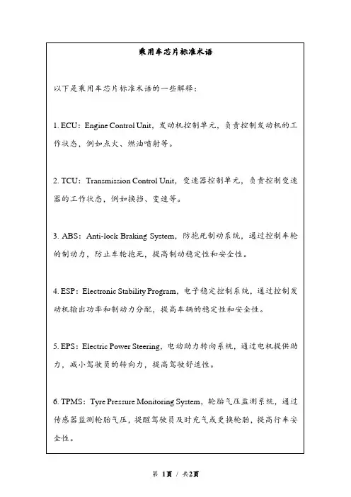
乘用车芯片标准术语以下是乘用车芯片标准术语的一些解释:1. ECU:Engine Control Unit,发动机控制单元,负责控制发动机的工作状态,例如点火、燃油喷射等。
2. TCU:Transmission Control Unit,变速器控制单元,负责控制变速器的工作状态,例如换挡、变速等。
3. ABS:Anti-lock Braking System,防抱死制动系统,通过控制车轮的制动力,防止车轮抱死,提高制动稳定性和安全性。
4. ESP:Electronic Stability Program,电子稳定控制系统,通过控制发动机输出功率和制动力分配,提高车辆的稳定性和安全性。
5. EPS:Electric Power Steering,电动助力转向系统,通过电机提供助力,减小驾驶员的转向力,提高驾驶舒适性。
6. TPMS:Tyre Pressure Monitoring System,轮胎气压监测系统,通过传感器监测轮胎气压,提醒驾驶员及时充气或更换轮胎,提高行车安全性。
7. ADAS:Advanced Driver Assistance Systems,高级驾驶辅助系统,是一种集成多种传感器和控制单元的系统,包括自适应巡航控制、车道偏离预警、自动泊车等功能,提高驾驶舒适性和安全性。
8. CAN:Controller Area Network,控制器局域网,是一种用于汽车电子控制单元之间通信的串行总线,用于传输控制信号和数据。
9. LIN:Local Interconnect Network,本地互连网络,是一种低速、低复杂度的串行通信协议,用于传输车辆内部控制单元之间的信号和数据。
10. OBD:On-Board Diagnostics,车载诊断系统,是一种用于检测和诊断车辆故障的系统,通过读取车辆控制单元的故障码,帮助维修人员快速定位和解决故障。
七格智联-小橘子系列-智能婴儿监护器使用说明书

使用产品前请仔细阅读本使用说明书,并妥善保管小橘子系列•智能婴儿监护器使用说明书产品清单婴儿监护器说明书电源适配器自攻螺丝膨胀管安装板电源线产品说明麦克风RESET 键镜头USB 电源接口彩色夜灯快装电源触点Micro SD 卡槽温湿度传感器指示灯推荐安装配件450mm(落地支架)(床夹支架)450mm90mm1125mm下载APP手机扫描说明书或包装上的二维码,或在APP 应用市场搜索“七格智联”,下载安装APP。
下载注册“七格智联”APP设备上电请使用原装电源适配器,将电源线插入监护器底座的电源插孔,接通电源,新设备进入初始化状态,等待约10秒后听到语音提示设备启动成功。
添加设备注册账号与添加设备功能说明哭声检测当检测到宝宝哭声时,自动播放安抚音乐,夜晚时自动点亮夜灯,同时推送报警信息。
虚拟围栏设置指定范围,当宝宝超出该区域,实时推送报警信息,有效保证宝宝安全。
危险区域侦测设置对宝宝有安全隐患的区域,当宝宝进入该区域,自动语音提醒宝宝尽快离开,及时推送报警信息,时刻守护宝宝安全。
音乐安抚内部集成了丰富的舒缓音乐、摇篮曲和自然音效,当检测到宝宝哭声时自动播放,及时安抚宝宝情绪,也可通过APP手动播放,帮助宝宝入睡。
智能多彩小夜灯集成九种颜色夜灯,陪宝贝告别黑暗恐惧,当检测到哭声时,夜灯自动打开,颜色和亮度可在手机APP上自由调节。
温湿度检测内置高精度温湿度传感器,可实时查看室内温湿度,如果超出舒适范围,家长可适当调整。
规格参数注意事项1.本产品工作温度为0-40℃,请勿在温度过高或过低的环境下使用。
2.本产品为精密电子产品,请勿在过度潮湿或可能会导致进水的环境下使用,以免损坏设备。
3.请确保本产品安装于2.4GHz Wi-Fi信号覆盖的范围内,并尽可能地放置于Wi-Fi信号强的位置,避免安装在金属、微波炉等可能对无线信号产生影响的位置。
常见故障排除• 配网时无法连接WiFi请确认无线网络为2.4GHz Wi-Fi且密码输入正确。
MICHELIN MEMS EVOLUTION 4 流体防护传感器用户手册说明书
Manuals+— User Manuals Simplified.MICHELIN Mems Evolution 4 Liquid Proof Sensor Owner’s ManualHome » MICHELIN » MICHELIN Mems Evolution 4 Liquid Proof Sensor Owner’s Manual PRODUCT NOTICEContents1 PRODUCT NAME MEMS2 PRODUCT DESCRIPTION3 FCC / IC CERTIFICATION4 PRODUCT SPECIFICATION5 DISPOSAL6 CONTACT DETAILS — TechnicalSupport7 Documents / ResourcesPRODUCT NAME MEMSEVOLUTION-4 LIQUID PROOF SENSOR — Part Number CA1564947PRODUCT DESCRIPTIONThe MEMS EVOLUTION-4 LIQUID PROOF SENSOR is a battery powered air pressure and air temperature sensor designed to operate inside tubeless earthmover tires.This information is sent, via a radio transmitter, to a MEMS EVOLUTION-4 TRANSCEIVER unit, which is usually mounted in the cab of the vehicle.FCC / IC CERTIFICATIONModel: RV1-30 FCC ID: F15-RV1-30G HVIN: RV1-30 IC: 5056A-RV130GPMN: MEMS EVOLUTION 4 LIQUID PROOF SENSORFederal Communications Commission (FCC) Statement 15.19 This device complies with Part 15 of the FCC Rules. Operation is subject to the following two conditions: 1) this device may not cause harmful interference and 2) this device must accept any interference received, including interference that may cause undesired. 15.195(a) This equipment has been tested and found to comply with the limits for a Class A digital device, pursuant to part 15 of the FCC Rules. These limits are designed to provide reasonable protection against harmful interference when the equipment is operated in a commercial environment. This equipment generates, uses, and can radiate radio frequency energy and, if not in stalled and used in accordance with the instruction manual, may cause harmful interference to radio communications. Operation of this equipment in a residential area is likely to cause harmful interference in which case the user will be required to correct the interference at his own expense.’‘15.21 You are cautioned that changes or modifications not expressly approved by the part responsible for compliance could void the user’s authority to operate the equipment.”‘FCC RF Radiation Exposure Statement:1. This Transmitter must not be co-located or operating in conjunction with any other antenna or transmitter.”2. This equipment complies with FCC RF radiation exposure limits set forth for an uncontrolled environment. Thisequipment should be installed and operated with a minimum distance of 29 centimeters between th e radiator and your body.Devices shall not be used for control of or communic ations with unmanned aircraft systems.Caution: Exposure to Radio Frequency Radiation1. To comply with the Canadian RF exposure compliance requirements, this device and its antenna must notbe co-located or operating in conjunction with any other antenna or transmitter.”2. To comply with RSS 192 RF exposure compliance requirements, a separation distance of at least 20 cm mustbe maintained between the antenna of this device and all persons.****************************MFP MICHELIN 23 Place des Carmes-Dechaux 63000 Clermont-Ferrand France The product must not be disposed of with unsorted waste, but must be sent to separate collection facilities for recovery and recycling Features, specifications are subject to change without notification. Document version 17.0 MFP MICHELIN © 2012 All rights reserved. Exclusive property of Manufacture Francaise des Pneumatiques Michelin. Any reproduction or utilization prohibited without the consent of Michelin.Documents / ResourcesMICHELIN Mems Evolution 4 Liquid Proof Sensor [pdf] Owner's ManualRV1-30G, FI5-RV1-30G, FI5RV130G, Mems Evolution 4, Liquid Proof Sensor, Mems Evolution4 Liquid Proof Sensor, SensorManuals+,。
orange-橙的电子-汽车胎压监测系统-TPMS-P409-Manual-手册-说明书
無線胎壓監測系統規格
胎壓感測發射器規格表 正常狀況下超過 7 年 -40oC to 125oC -30oC to 120oC 最大 95% 433.92MHz 0~74 psi 正常操作狀態下± 1psi ± 4oC (一般正常環境下) 最大 5 dBm 3.0V 32g ±3 g
接收顯示器規格表 直流 12V < 200mA -30oC to 105oC -30oC to 85oC
2/17
Manual for Tire Pressure Monitoring Systems, TPMS
電池使用壽命 感測器儲存溫度 感測器工作溫度 感測器工作濕度 感測器工作頻率 輪胎壓力監測範圍 胎壓讀取誤差值 溫度讀取誤差值 感測器功率 電池容量 感測器重量
操作電壓 操作電流 監測器儲存溫度 監測器工作溫度
附錄 1 ........................................................................................... 16 附錄 2 ........................................................................................... 16 系統保固 .Байду номын сангаас..................................................................................... 17
胎壓過低警告值設定................................................................................................................ 8 胎壓過高警告值設定................................................................................................................ 8 胎溫過高警告值設定................................................................................................................ 9 異常警告說明 .......................................................................................................................... 9
SMC Flex Smart Motor Controller 18产品说明书
Visit our website: /catalogsBulletin 150SMC™ Flex Smart Motor Controller18FeaturesDescription of FeaturesElectronic Motor Overload ProtectionThe SMC Flex controller incorporates, as standard, electronic motor overload protection. This overload protection is accomplished electronically with an I 2t algorithm.When coordinated with the proper short circuit protection, overload protection is intended to protect the motor, motor controller, and power wiring against overheating caused by excessive overcurrent.The SMC Flex controller meets applicable requirements as a motor overload protective device.The controller’s overload protection is programmable, providing the user with flexibility. The overload trip class consists of either OFF ,10, 15, 20 or 30 protection. The trip current is programmed by entering the motor full-load current rating, service factor, and selecting the trip class.Thermal memory is included to accurately model motor operating temperature. Ambient temperature insensitivity is inherent in the electronic design of the overload.Stall Protection and Jam DetectionMotors can experience locked-rotor currents and develop high torque levels in the event of a stall or a jam. These conditions can result in winding insulation breakdown or mechanical damage to the connected load. The SMC Flex controller provides both stall protection and jam detection for enhanced motor and systemprotection. Stall protection allows the user to program a maximum stall protection delay time from 0…10 seconds. The stall protection delay time is in addition to the programmed start time and begins only after the start time has timed out. If the controller senses that the motor is stalled, it will shut down after the delay period has expired. Jam detection allows the user to determine the motor jam detection level as a percentage of the motor’s full-load current rating. To prevent nuisance tripping, a jam detection delay time,from 0.0…99.0 seconds, can be programmed. This allows the user to select the time delay required before the SMC Flex controller will trip on a motor jam condition. The motor current must remain above the jam detection level during the delay time. Jam detection is active only after the motor has reached full speed.Underload ProtectionUtilizing the underload protection of the SMC Flex controller, motor operation can be halted if a drop in current is sensed.The SMC Flex controller provides an adjustable underload trip setting from 0…99% of the programmed motor full-load current rating with an adjustable trip delay time of 0…99 seconds.Undervoltage ProtectionThe SMC Flex controller’s undervoltage protection will halt motor operation if a drop in the incoming line voltage is detected.The undervoltage trip level is adjustable as a percentage of theprogrammed line voltage, from 0…99%. To eliminate nuisance trips,a programmable undervoltage trip delay time of 0…99 seconds can also be programmed. The line voltage must remain below the undervoltage trip level during the programmed delay time.Overvoltage ProtectionIf a rise in the incoming line voltage is detected, the SMC Flex controller’s overvoltage protection will halt motor operation.The overvoltage trip level is adjustable as a percentage of the programmed line voltage, from 0…199%. To eliminate nuisance trips, a programmable overvoltage trip delay time of 0…99 seconds can also be programmed. The line voltage must remain above the overvoltage trip level during the programmed delay time.Voltage Unbalance ProtectionVoltage unbalance is detected by monitoring the 3-phase supply voltage magnitudes in conjunction with the rotational relationship of the three phases. The controller will halt motor operation when the calculated voltage unbalance reaches the user-programmed trip level.The voltage unbalance trip level is programmable from 0…25%unbalance.Excessive Starts Per HourThe SMC Flex controller allows the user to program the allowed number of starts per hour (up to 99). This helps eliminate motor stress caused by repeated starting during a short time period.MeteringPower monitoring parameters include:Note:The motor thermal capacity usage allows the user to monitorthe amount of overload thermal capacity usage before the SMC Flex controller’s built-in electronic overload trips.Built-in DPI Communication CapabilitiesA serial interface port is provided as standard, which allowsconnection to a Bulletin 20 Human Interface Module and a variety of Bulletin 20-COMM Communication Modules. This includes Allen-Bradley Remote I/O, DeviceNet, ControlNet, Ethernet, ProfiBUS,Interbus, and RS485-DF1.LCD DisplayThe SMC Flex controller’s three-line 16-character backlit LCD display provides parameter identification using clear, informative text. Controller set up can be performed quickly and easily without the use of a reference manual. Parameters are arranged in an organized four-level menu structure for ease of programming and fast access to parameters.Keypad ProgrammingProgramming of parameters is accomplished through a five-button keypad on the front of the SMC Flex controller. The five buttons include up and down arrows, an Enter button, a Select button, and an Escape button. The user needs only to enter the correctsequence of keystrokes for programming the SMC Flex controller.Auxiliary ContactsFour fully programmable hard contacts are furnished as standard with the SMC Flex controller:Aux #1, Aux #2, Aux #3, Aux #4Ground Fault InputThe SMC Flex can monitor for ground fault conditions. An external core balance current transformer is required for this function. See SMC Flex User Manual for additional information.Tach InputA motor tachometer is required for the Linear Speed Start mode.Please see the Specifications section page 36 for tachometer characteristics.PTC InputA motor PTC input can be monitored by the SMC Flex. In the event of a fault, the SMC Flex will shut down and indicate a motor PTC fault.y N.O./N.C.y Normal/Up-to-Speed/External Bypass/Fault/Alarm/Network Network I/OThe SMC Flex can have up to two (2) inputs and four (4) outputs controlled via a communication network. The output contacts use the auxiliary contacts.y 3-phase current y Power Factory 3-phase voltage y Motor thermal capacity usage y Power in kW or mWy Elapsed time y Power usage in kWH or mWHy。
Kidde Wi-Fi 3-in-1 气质量监测报警器说明书
Kidde's Wi-Fi alarms are compatible with Amazon "Just Ask Alexa"and Google "Hey Google" voice assistant commands. Use simple voice commands to check the status of your device. Let’s get you set up!Get Started with Alexa1. Install the Kidde app from the App Store or Google Play, or scan the QRcode shown in Step 1 of the Quick Start Guide included with your Wi-Fi device.2. Open the Kidde app, create and activate your account.3. Tap “Add a device” and select the appropriate Kidde Wi-Fi device.4. Follow the in-app steps to set up and connect your Wi-Fi device to theapp.5. After setup is complete, in your Kidde app:–Click on “Account”–Scroll down to SMART HOME INTEGRATIONS–Select the “Alexa” toggle button6. Now close the Kidde app and open the Alexa app.7. In your Alexa app:–Click on “More”–Click on “Skills & games”–Click the Magnifying Glass and search for “Kidde Alarm”–Click on “Kidde Alarm”–Click on “Launch”8. Once enabled, log in with your Kidde app usernameand password.You’re all set to use your Kidde Wi-Fi device through Alexa.Just say “Alexa...”*Per UL standards, Test and Smart Hush™ are not available using voice assistants.Just ask Alexa:“Alexa, ask Kidde alarm statusin the Kitchen.”“Alexa, ask Kidde alarm thesmoke level in the Kitchen.”“Alexa, ask Kidde alarm carbonmonoxide level in the LivingRoom.”“Alexa, ask Kidde alarm batterylevel in the Living Room.”“Alexa, ask Kidde alarm aboutmy air quality.”or“Alexa, ask Kidde alarm airquality in the Living Room.”Amazon, Alexa and all related marks are trademarks ofA Carrier Company©2023 Carrier. All Rights Reserved.®Get Started with Google Home1. Install the Kidde app from the App Store or Google Play, or scan theQR code shown in Step 1 of the Quick Start Guide included with your Wi-Fi device.2. Open the Kidde app, create and activate your account.3. Tap “Add a device” and select the appropriate Kidde Wi-Fi device.4. Follow the in-app steps to set up and connect your Wi-Fi device to theapp.5. Install the Google Home app and log in with your Google Account.6. In your Google Home app:–Tap + (Add) and Select “Set Up Device”–Select “Works With Google”–Click Magnifying Glass and search “Kidde Alarm”–Click link and log in to your Kidde app account–Click OKYou’re all set to use your Kidde Wi-Fi device through Google Home. Just say “Hey Google...”*Per UL standards, Test and Smart Hush™ are not available usingvoice assistants.Just say “Hey Google...”“Hey Google, what is thesmoke level in the LivingRoom?”“Hey Google, what is thecarbon monoxide level in theLiving Room?”“Hey Google, what is thebattery level in the LivingRoom?”“Hey Google, what is the airquality in Living Room?”Google and Google Home are trademarks of Google LLC.A Carrier Company©2023 Carrier. All Rights Reserved.®。