常吃这两类食物100%患肝癌
2025年中图版八年级数学上册月考试卷含答案
2025年中图版八年级数学上册月考试卷含答案考试试卷考试范围:全部知识点;考试时间:120分钟学校:______ 姓名:______ 班级:______ 考号:______总分栏题号一二三四五六总分得分评卷人得分一、选择题(共7题,共14分)1、如图,在△ABC中,∠BAC=90°,AB=AC,∠ABC的平分线交AC于D,过C作BD垂线交BD的延长线于E,交BA的延长线于F,那么①BD=FC;②∠ABD=∠FCA;③BC=2C E;④CE=FE.其中正确的结论的个数()A. 4个B. 3个C. 2个D. 1个2、下列说法错误的是()A. 中的a可以是正数、负数、零B. 中的a不可能是负数C. 数a的平方根有两个,它们互为相反数D. 数a的立方根只有一个3、关于x的一元二次方程kx2﹣2x﹣1=0有两个不相等的实数根,则k的取值范围是()A. k>﹣1B. k<1C. k>﹣1且k≠0D. k<1且k≠04、如图,在等腰梯形ABCD中,AD∥BC,AB=DC,∠B=80o;则∠D的度数是()A.B.C.D.5、已知ab是实数,x=a2+b2+20y=4(2b鈭�a)x则xy的大小关系是( )A. x鈮�yB. x鈮�yC. x<yD. x>y6、下列各式中,能用平方差公式分解因式的是()A. 4x2鈭�4x+1B. 鈭�a2+b2C. x2+y2D. 鈭�x2鈭�y27、下列线段不能构成直角三角形的是()A. 5,12,13B. 2,3,C. 4,7,5D. 1,,评卷人得分二、填空题(共6题,共12分)8、在抛掷一枚硬币,考察出现正、反面的实验中,随着实验次数据的增加,出现正面的频率将趋于稳定在____.9、当x____时,分式有意义.10、分解因式:= _____________ 。
11、若将函数y=-2x+2向下平移5个单位长度,则得到的函数表达式是____.12、(2010秋•安阳期末)如图,在△ABC和△DEF中,如果AB=DE,BE=CF,只要添加条件____(只写一个即可),就可以证得△ABC≌△DEF.13、(2009秋•怀远县期末)如图所示,∠B=∠D=90°,要证明△ABC与△ADC全等,还需要补充的条件是____.(填上一个条件即可)评卷人得分三、判断题(共8题,共16分)14、任何有限小数和循环小数都是实数.____.(判断对错)15、若x>y,则xz>yz.____.(判断对错)16、2的平方根是____.17、正方形的对称轴有四条.18、判断:只要是分式方程,一定出现增根. ()19、关于某一条直线对称的两个图形叫轴对称图形.20、如图直线a沿箭头方向平移1.5cm,得直线b。
Recom RP100H-RW DC DC 转换器产品说明书

FeaturesRegulated Converter• 4:1 wide input range• 3kVAC reinforced insulation for 110Vin 2.25kVDC basic insulation for 24Vin & 48Vin • Efficiency up to 93%• No minimum load required• EN50155, IEC/EN60950-1 & UL60950-1 certifiedDescriptionThe half-brick RP100H series DC/DC converters are designed for railway rolling stock and high voltage battery applications. Each series has three 4:1 input voltage range options to cover all input voltages from 9VDC up to 160VDC with isolated and regulated 5V to 48VDC outputs. The converters have high efficiencies and metal base-RP100H-RW DC/DC Converter100 Watt Half BrickEN50155 certifiedIEC/EN60950-1 certified UL60950-1 certifiedE196683RP100H-2415SRW 9-36 15 6700 4601 100 91 4460RP100H-2424SRW 9-36 24 4200 4666 101 90 1750RP100H-2448SRW 9-36 48 2100 4666 101 90 430RP100H-4805SRW 16.5-75 5 20000 2240 100 93 40000RP100H-4812SRW 16.5-75 12 8400 2333 101 90 7000RP100H-4815SRW 16.5-75 15 6700 2300 100 91 4460RP100H-4824SRW 16.5-75 24 4200 2333 101 90 1750RP100H-4848SRW 16.5-75 48 2100 2307 101 90 430RP100H-11005SRW 43-160 5 20000 1010 100 93 40000RP100H-11012SRW 43-160 12 8400 1018 101 90 7000RP100H-11015SRW 43-160 15 6700 1015 100 91 4460RP100H-11024SRW 43-160 24 4200 1018 101 90 1750RP100H-11048SRW 43-160 48 2100 1007 101 90 430Ordering ExamplesRP100H-2405SRW/N = 24V Input, 5V Output, Single, Neg. CTRL function RP100H-11012SRW/P = 110V Input, 12V Output, Single, Pos. CTRL functionRP100H-2405SRW/N-HC = 24V Input, 5V Output, Single, Neg. CTRL function, premounted Heat-sinkModel NumberingInput Voltage Output VoltageS ingleRP100H-__ __SRW/_ _Notes:Note2: standard part is with suffix “P” for positive logic (1=ON, 0=OFF) or add suffix “N” instead for negative logic (0=ON, 1=OFF) Note3: add suffix “-HC” for premounted Heat-sink CTRL Logic (2)Package (3)Notes:Note1:Efficiency is tested by nominal Vin, full load and at 25°Chttps:///pdf/Powerline_DC-DC/RSPxxx-168.pdf/eval-ref-boardsSpecifications (measured @Ta = 25°C, resistive load, nominal Vin and rated Iout unless otherwise noted)Specifications (measured @Ta = 25°C, resistive load, nominal Vin and rated Iout unless otherwise noted)RP100H-4805SRW708090100Efficiency vs. Output CurrentPower up Start-up CharacteristicON/OFF Control Start-up Rise CharacteristicSpecifications (measured @Ta = 25°C, resistive load, nominal Vin and rated Iout unless otherwise noted)Efficiency vs. Input Voltage60708090100708010090RP100H-11005SRWEfficiency vs. Output CurrentPower up Start-up CharacteristicSpecifications (measured @Ta = 25°C, resistive load, nominal Vin and rated Iout unless otherwise noted)OUTPUT TRIM Typical Output Ripple and NoisePower up Start-up CharacteristicOutput Voltage TrimmingRP100H-RW converters offer the feature of trimming the output voltage over a certain range around the nominal value by using external trim resistors. The values for trim resistors shown in trim tables below are according to standard E96 values; therefore, the specified voltage may slightly vary; they also can be calculated with below shown equation.TRIM DOWNTRIM UPTRIM-Sense+SenseSpecifications (measured @Ta = 25°C, resistive load, nominal Vin and rated Iout unless otherwise noted)OUTPUT TRIMRP100H-xx05SRWRP100H-xx12SRWRP100H-xx15SRWRP100H-xx24SRWRP100H-xx48SRWTrim Down all Vout‘sTrim up 12345678910%Vout = 5.05 5.10 5.15 5.20 5.25 5.30 5.35 5.4 5.45 5.50Volts R 1 = 30915810578.763.453.646.440.236.533.2kOhms Trim up 12345678910%Vout =12.1212.2412.3612.4812.6012.7212.8412.9613.0813.20Volts R 1 = 88745330122618215413311810595.3kOhms Trim up 12345678910%Vout =15.1515.3015.4515.6015.7515.9016.0516.2016.3516.50Volts R 1 = 1130576383294237196169150137124kOhms Trim up 12345678910%Vout =24.2424.4824.7224.9625.2025.4425.6825.9226.1626.40Volts R U = 1870953634487392324280249226205kOhms Trim up 12345678910%Vout =48.4848.9649.4449.9250.4050.8851.3651.8452.3252.80Volts R 1 = 3830196013001000806681576511464422kOhms Trim down 12345678910%R 2 = 97.647.531.623.217.814.712.110.59.098.06kOhms Trim down 11121314151617181920%R 2 =7.156.345.765.114.644.223.923.573.243.01kOhmsTrim CalculationVout = Output VoltageR 1 =100*Vout+D Vout * Vout)- (100+2D Vout) k Ω D Vout = Output Voltage Trim in %1.225*D Vout D VoutR1 =trim up resistorR2 = trim down resistor R 2 = 100 - 2 k ΩD Vout Practical Example:Trim Up:Vout = 5V, D Vout = 10% (5.5V)R 1 =100*Vout+D Vout * Vout) - (100+2D Vout) k Ω = 100*5 +10*5 - 100+2*10= 44.89 - 12 = 32.9k Ω 1.225*D Vout D Vout 1.225*10 10Trim down:Vout = 5V, D Vout = -10% (4.5V)R 2 = 100 - 2 k Ω = 100 - 2 = 8.06k ΩD Vout 10Specifications (measured @Ta = 25°C, resistive load, nominal Vin and rated Iout unless otherwise noted)REGULATIONSParameter Condition ValueOutput Accuracy±1.0%Line Regulation low line to high line at full load±0.1% Load Regulation0% to 100% load0.1% Transient Response25% load step change200µs typ.; 250µs max.Transient Response to Dynamic Load Change from 100% to 75% to 100% of Full Load at nom.VinRP100H-4805SRWRP100H-2405SRWRP100H-11005SRWSpecifications (measured @Ta = 25°C, resistive load, nominal Vin and rated Iout unless otherwise noted)ENVIRONMENTALParameterCondition ValueOperating Case Temperature Range refer to derating graphMaximum Case Temperature 105°CTemperature Coefficient ±0.02%/°C max.Thermal Impedance vertical direction by natural convection (0.1m/s) without Heat-sink vertical direction by natural convection (0.1m/s) with Heat-sink6.7°C/W 4.7°C/W Operating Humidity 5% - 95% RHPollution Degree PD2Shock according to EN61373 standard Thermal Shock according to MIL-STD-810F standardVibrationaccording to EN61373 standardFire protection on railway vehicles according to EN45545-2, 2013 standardMTBFaccording to MIL-HDBK-217F standard, 25°C408.7 x 103 hoursPROTECTIONSParameterConditionValueShort Circuit Protection (SCP)below 100m Ωcontinuous, automatic recovery Over Voltage Protection (OVP)% of nom. Vout115%-130%, Hiccup Mode Over Load Protection (OLP)% Iout rated24Vin, 48Vin 110Vin120%-150%, Hiccup Mode 150% typ., Hiccup ModeOver Temperature Protection (OTP)+110°C to +120°C Isolation Voltage110VinI/P to O/P I/P or O/P to Case 3kVAC/1minute 1.5kVAC/1minute 24Vin, 48VinI/P to O/P I/P or O/P to Case2.25kVDC/1minute 1.6kVDC/1minuteIsolation Resistance 500 VDC1G Ω min.Isolation Capacitance 2500pF max.Isolation Grade110 Vin 24Vin, 48Vin reinforced insulationbasic insulationThermal CalculationNotes:Note4: Refer to local wiring regulations if input over-current protection is also required. Recommended fuse: T35A slow blow.R thcase-ambient = 6.7°C/W (vertical) T case = Case Temperature R thcase-ambientHC = 4.7°C/W (vertical) T ambient = Environment Temperature P dissipation = Internal lossesR thcase-ambient = T case - T ambientP IN = Input PowerP dissipationP OUT = Output Power h = Efficiency under given Operating ConditionsP dissipation = P IN - P OUT = P OUTapp- P OUTapp R thcase-ambient = Thermal Impedance h Practical Example:Take the RP100H-2405SRW with 9V input Voltage and 50% load. What is the maximum ambient operating temperature? Use converter vertical in application without airflow.Eff min = 91% @ V nomP OUT = 100W P OUTapp = 100 x 0.5 = 50W h = 91% (Efficiency vs. Load Graph)without Heat-sink with Heat-sinkR th = T casemax - T amb --> 6.7°C/W = 105-T amb R thHC = T casemax - T amb--> 4.7°C/W = 105-T amb P dissipation 4.95W P dissipation4.95W T amb = 72°C T ambHC = 82°CSpecifications (measured @Ta = 25°C, resistive load, nominal Vin and rated Iout unless otherwise noted)Specifications (measured @Ta = 25°C, resistive load, nominal Vin and rated Iout unless otherwise noted)DC/DC ConverterSpecifications (measured @Ta = 25°C, resistive load, nominal Vin and rated Iout unless otherwise noted)RP100H-RWSeriesConducted Emission EN55022 Class AConducted Emission EN55022 Class AC4C5C6C7C8Shield PlaneL1C18+V INEMI Filtering according to EN55022/11 Class A and EN50121-1 (110Vin)DC/DC ConverterSpecifications (measured @Ta = 25°C, resistive load, nominal Vin and rated Iout unless otherwise noted)RP100H-RWSeriescontinued on next pageEMI Filtering according to EN55022/11 Class B (24Vin and 48Vin)Shield Plane100-110xxSRW, Class BNNC6C9C8C3C4CaseL2C7C19C20Shield PlaneC12C13C14C10C11C16C2C4L1L2C5C8C6C7C11C3Conducted Emission EN55022 Class ADC/DC ConverterSpecifications (measured @Ta = 25°C, resistive load, nominal Vin and rated Iout unless otherwise noted)RP100H-RWSeriesEMI Filtering according to EN55022/11 Class B (110Vin)C8Shield PlaneShield PlaneC9C1C2C3C11C12C10CaseL1C4C5C8C13C14C17C9C19C3C4L1L2C12C10C11C15C15Shield PlaneC9C10C12Conducted Emission EN55022 Class BSpecifications (measured @Ta = 25°C, resistive load, nominal Vin and rated Iout unless otherwise noted)Specifications (measured @Ta = 25°C, resistive load, nominal Vin and rated Iout unless otherwise noted)The product information and specifications may be subject to changes even without prior written notice.The product has been designed for various applications; its suitability lies in the responsibility of each customer. The products are not authorized for use in safety-critical applications without RECOM’s explicit written consent. A safety-critical application is an application where a failure may reasonably be expected to endanger or cause loss of life, inflict bodily harm or damage property. The applicant shall indemnify and hold harmless RECOM, its affiliated companies and its representatives against any damage claims in connection with the unauthorizeduse of RECOM products in such safety-critical applications.PACKAGING INFORMATIONParameterTypeValuePackaging Dimension traywithout Heat-sink with Heat-sink157.0 x 88.0 x 12.8mm 157.0 x 88.0 x 24.8mmPackaging Quantity 2pcs.Storage Temperature Range -55°C to +125°C Storage Humidity5% - 95% RH。
BT100 Bass Amplifier用户指南说明书

BT100 BASS AMPLIFIER USER’S GUIDEIntroduction . . . . . . . . . . . . . . . . . . . . . . . . . . . . . . . . .3The Front Panel . . . . . . . . . . . . . . . . . . . . . . . . . . . .4,5The Rear Panel . . . . . . . . . . . . . . . . . . . . . . . . . . . . . .5Some Suggested Settings . . . . . . . . . . . . . . . . . . . . . .6System Block Diagram . . . . . . . . . . . . . . . . . . . . . . . .7Technical Specifications . . . . . . . . . . . . . . . .back cover2Congratulations!You are now the proud owner of the Crate BT100 Bass Amplifier. The BT100 features two different channels: a distortion channel, featuring Crate’s exclusive Shape control for quick and easy access to the tone you need, and a clean channel with a four-band rotary EQ. Another unique and valuable feature of this amplifier is the Octave control. This feature electronically creates a second signal that is one octave lower than the original signal. An active electronic tuner, conveniently located on top of the amplifier, allows you to get in tune and stay in tune “on the fly.” The Mute switch allows you to tune in silence without changing the channel Level controls. A built-in Limiter keeps your sound clean even at full output power levels, and front panel jacks are provided for connecting a CD player and a pair of headphones, thereby optimizing your practice time.Like all Crate products, your BT100 is designed by musicians and built using only the best components. Extensive testing at the hands (and ears) of skilled technicians and musi-cians insures you that this amplifier is the absolute best it can be.In order to get the most out of your new bass amp, we urge you to check out the infor-mation in this manual before you begin playing.And thank you for choosing Crate.Declaration Of Conformity#34, Effective 01-01-2001Manufacturer’s Name:SLM ElectronicsProduction Facility:1901 Congressional Drive, St. Louis, MO 63146, USAProduction Facility:700 Hwy 202 W, Yellville, AR 72687, USAShipping Facility:1400 Ferguson Ave., St. Louis, MO 63133, USAOffice Facility:1400 Ferguson Ave., St. Louis, MO 63133, USAProduct Type:Audio AmplifierComplies with the following Standards:Safety:EN60065, E60065, C22.2, UL6500 and/or UL813EMC:Directive 89/336/EEC, EN55103, EN55013, EN61000,and/or FCC 47CFR 15B clASupplementary information provided by:SLM Electronics - R & D Engineering1901 Congressional Drive, St Louis, MO 63146, USATel.: 314-569-0141, Fax: 314-569-0175341. INPUT:Use this 1/4” jack to connect your bass to the amplifier by means of a shielded instrument cable.2. -15dB/0dB:Use this switch to match the output signal level of your instrument to the amplifier. If your instru-ment has standard pickups, setting the switch to the 0dB position (switch in the out position) should yield the best results. If your bass has active electronics or high output pickups, set the switch to the -15dB position (switch depressed).3. MUTE:This switch, when depressed, interrupts the signal prior to the power amplifier, allowing you to tune your instrument in silence.4. GAIN:Use this control to adjust the amount of distortion for the Distortion channel. As you rotate the control clockwise the amount of distortion increases.NOTE:The BT100 employs an internal noise gate on the Distortion channel to keep residual noise to a minimum.The Clean channel’s Level control (#8) must be turned up above “0” in order for the noise gate to trigger proper-ly. The Gain control (#4) and input signal level also affect the noise gate.5. SHAPE:Use this control to adjust the tone of the Distortion channel, from a studio “V”-shaped tone to a more “live,” more present sound.6. LEVEL:Use this control to adjust the output level of the Distortion channel.7. CHANNEL SWITCH:Use this switch to select either channel. With the switch in the out position, the Clean channel is selected. When the switch is depressed, the Distortion channel is selected. The adjacent LED illumi-nates when the Distortion channel is selected. NOTE:When using a footswitch: when this switch is depressed,the footswitch switches between the Distortion channel and the Clean channel; when this button is in the out posi-tion, the Clean channel is always active, and the footswitch turns the Distortion channel on and off, allowing you a blend of both channels.8. LEVEL:Use this control to adjust the output level of the Clean channel, and as part of the Octave level control (see #13).9. LOW:Use this control to adjust the low frequency output of the Clean channel.10. LOW MID:Use this control to adjust the lower-midrange frequency output of the Clean channel.11. HIGH MID:Use this control to adjust the upper-midrange frequency output of the Clean channel.12. HIGH:Use this control to adjust the high frequency output of the Clean channel.13. OCTAVE:The BT100 features internal circuitry which creates a second signal which is one octave lower than the input signal. Use this control in conjunction with the Clean channel’s Level control (#8) to adjust the level of the octave signal.14. MASTER:Use this control to adjust the overall output level of the amplifier.15. LIMIT LED:This LED illuminates when the internal limiting circuit is active. Occasional flashing during play-ing is normal. If the Limit LED remains illuminated, reduce the output level of the amplifier until the LED flashes.16. CD INPUT:Use these RCA jacks to connect the line level (or headphones) output of a CD player, tape deck or rhythm machine to the amplifier. The signal level from these jacks is adjusted by the Master control (#14). If the signal from the source connected to these jacks is too strong, use the output level control on the source to adjust the signal to obtain the proper level for a good mix.17. HEADPHONES:Use this jack to listen to the amplifier through a pair of stereo headphones. The internal speaker is disconnected when the headphones jack is used. To avoid possible damage to your hearing, do not use headphones for extended periods of time at extremely loud listening levels.The Front Panel:518. POWER:Use this switch to turn the amplifier on and off. The adjacent LED illuminates when the amplifier is turned on.19. ELECTRONIC TUNER (top panel, not shown):This active electronic tuner is on whenever the amplifier is turned on, allowing you constant, “real-time” tuning. The tuner is fully chromatic – use the flat and sharp indica-tors until the LED between them illuminates, indicating proper tuning.The Rear Panel:20. AC LINE CORD (not shown):The grounded power cord should only be plugged into a grounded power out-let that meets all applicable electrical codes and is compatible with the voltage, power, and frequency require-ments stated on the rear panel. Do not attempt to defeat the safety ground connection.21. EXTERNAL SPEAKER:Use this jack to connect the amplifier to an external speaker cabinet. This jack is wired in series with the internal speaker, which remains active when this jack is used. A 4 ohm external speaker cabinet is recommended.22. FOOTSWITCH:Connect a two-button footswitch (such as the Crate CFS-2) here for remote control of the channel selection/“blend” (see #7) and octave on/off. (When the Channel Switch [#7] is depressed, the footswitch switches between the Clean channel and the Distortion channel; when the switch is in the out position, the Clean channel is always active, and the footswitch turns the Distortion channel on and off, allowing you a blend of both channels.)23. EFFECTS LOOP SEND:Use this jack to connect an external signal processor to the amplifier by means of a shielded signal cable. Connect the other end of this cable to the input jack of the external processor.24. EFFECTS LOOP RETURN:Use this jack to connect an external signal processor to the amplifier by means of a shielded signal cable. Connect the other end of this cable to the output jack of the external processor.25. BALANCED LINE OUT:Use this XLR jack to send a balanced line level signal to an external power amplifi-er, mixing board, or recording console.26. PRE/POST:Use this switch to determine whether the Balanced Line Out signal is Post-EQ (switch depressed)or Pre-EQ (switch in the out position).27. GROUND LIFT:This switch, when depressed, lifts the ground connection at the Balanced Line Out jack (#25).This may help reduce hum in the Balanced Line Out signal.28. VOLUME: Use this control to adjust the signal level at the Balanced Line Out jack (#25).POSTGND67BUFFEREQNOISE GATETUNERA BC D EF GSHAPEOCTAVEBALANCED EFFECTS BLENDEXTERNAL SENDPHONESPOWER SPEAKERATTENUATORRETURN SWITCHING CIRCUITRYBT100 Technical Specifications:Specifications subject to change without notice©2003 ST. LOUIS MUSIC, 1400 FERGUSON, ST. LOUIS, MO. 6313347-673-01 • 012904。
Converge SR 1212A数字矩阵混音器与四通道电源放大器数据资料说明书

Converge TM|SR 1212ADigital Matrix Mixer with Four Channel Power AmplifierConverge Pro DATA SHeeT <THE ULTIMATE IN AUDIO PROCESSING AND DIGITAL MATRIX MIXING APPLICATIonSBoardroomsTraining CentersMunicipal RoomsCourtroomsHouses of WorshipTelemedicinePresentation SystemsZoned PagingMasking SystemsADvAnTAgeSAdvanced Feature SetManagement Improvements+Integrated Ethernet and USB connections>SNMP and HTML remote management agents>Event scheduler>Diagnostic console>Simplified Configuration Software+Drag & drop A/V and channel objects>Selectable views -- unit, matrix, channel>Expanded serial command set+Superior Audio PerformanceDARE™ (Dynamic Automatic Resonance Elimination) for control of feedback+Unique automatic mixing process delivers optimum intelligibility+20 Hz-22 kHz bandwidth for full-range audio response+ALC & AGC keep participants’ audio balanced and consistent+Advanced Digital Processing on each amplifier channel+Configuration FlexibilityFour built-in 35 Watt amplifiers, 8Ω or 70V/100V+Up to 96 microphones+Link multiple Converge/Converge Pro units (Converge Pro 880, 880T, 880TA, 840T, 8i, TH20,+Converge SR 1212 and SR 1212A) for extensive microphone coverage and up to 16 phonelinesEnhanced expansion bus, featuring 18 mix-minus audio buses for routing between units+Ten mic gating groups (four internal & six global) allow separation of mics into individual+mixer gating groups for greater configuration flexibility32 presets can be executed on-the-fly without disturbing other ongoing preset operations+255 Macros for customized audio control/configuration with single command execution+No space required between rack mounted units+NEw!Audio PerformanceConditions: Unless otherwise specified,all measurements are performedfrom 20 Hz to 22 kHz Bw limit (no weighting)Frequency Response: 20 Hz to 22 kHz+/- 1 dBNoise (EIN): -126 dBu, 20 kHz Bw,max gainRs= 150ΩTHD+ Noise: <0.02%Dynamic Range: >105 dB (non A weighted)Crosstalk: <-91 dB re 20 dBu full band. Mic/Line Inputs 1-8Push-on mini-terminal block, balanced, bridgingImpedance: > 5 KΩNominal Level: adjustable -56 dBu to 0 dBu (7dB step coarse gain adjustment) Maximum Level: -65 to +20 dBu Phantom Power: 24V, selectableLine Inputs 9-12Push-on mini-terminal block, balanced, bridgingImpedance: > 5 KΩNominal Level: 0 dBuMaximum Level: 20 dBuoutput 1-8Push-on mini-terminal block, balanced, bridgingImpedance: < 50ΩNominal Level: 0 dBuMaximum Level: 20 dBuAuto Mixer ParametersNumber of Open Microphones (NOM)PA Adaptive ModeFirst Mic Priority ModeMaximum # of MicsAmbient LevelGate Threshold AdjustOff Attenuation AdjustHold TimeDecay RateChairman Override96 T otal Microphones per site6- Global Gating Groups4- Internal Gating Groups Matrix Mixing Parameters8- Microphone Analog Inputs4- Analog Line Inputs8- Analog Line Outputs4- Power Amplifier Outputs18- Expansion Bus in/out8- Assignable Processing Blocks in/outAssignable Processing BlocksFiltersAll PassLow PassHigh PassLow shelvingHigh shelvingPEQNotchCrossoversCD HornCompressorDelay: adjustable up to 250 msPower Amplifier output ProcessingFeedBack Elimination w/ring cancellation10-band EQ filter4-node filter bank for CrossoverDelay BlockCompressor/LimiterNoise Gate for Hiss ControlSound Masking Generator per channelAdaptive Volume ControlMulti Channel ControlMicrophone Processing4-node filter bankAGC/ALCPower AmplifiersChannels: 4Amplifier Output: 4x35 Watts into 8ΩImpedance: Selectable 8Ω, 70V, 100VTHD + Noise: <0.2% (1/3 Power)Crosstalk: <-68 dBexpansion BusConnection: CAT 5, RJ45Mix Minus Structure18 Audio Buses6 Gating Buses8 Reference Busesnetwork10/100 Auto Switching (PC andNetwork Port)HTTP ServerT elnet ClientSNMP AgentSMTP ClientDNSDHCPrS-232DB-99.6k – 115k baud8/1/0Hardware Flow ControlUSBVersion 2.0 compatibleT ype: B-connectorgPIoDB 25 female (A/B)Inputs: Active LowOutputs: Open Collector, 40Vdc, 40 mAPower100-240VAC; 50/60 Hz,300 watts (maximum)Idle: 139 BTU/hrFull Load: 779 BTU/hrEfficiency: >80%Humidity15 to 80%MechanicalDimensions: 2RU3.5” H x 17.25” w x 15.92” Dweight: < 30 lbs.environmentalOperating temperature:32-122 degrees FComplianceFCCIndustry CanadaCERoHSClass 2 wiring RequiredPart number910-151-901 Converge SR 1212ACONVERGE PRO SR 1212A DATA SHeeT <> Converge Pro Sr 1212A BACK PAneL > SPeCIFICATIonS> CLeArone LoCATIonSHeadquarters:Salt Lake City, UT USA 5225 wiley Post way Suite 500Salt Lake City, UT 84116 Tel: 801-975-7200T oll Free: 800-945-7730 Fax: 801-977-0087******************Latin AmericaTel: 801-974-3621*******************EMEATel: 44 (0) 1189 036 053*******************APACTel: 801-303-3388*******************Other product names may be registered trademarks of their respective owners who do not necessarily endorse ClearOne or ClearOne’s products. All rights reserved. Information in this document subject to change without notice.© ClearOne. 802-151-901-DS Revision 1.9。
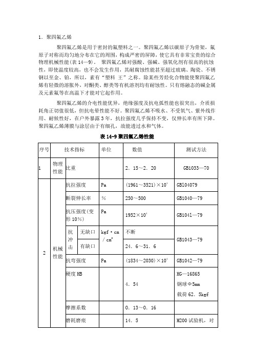
聚四氟乙烯材料力学性能参数表
1.聚四氟乙烯聚四氟乙烯是用于密封的氟塑料之一。
聚四氟乙烯以碳原子为骨架,氟原子对称而均匀地分布在它的周围,构成严密的屏障,使它具有非常宝贵的综合物理机械性能(表14—9)。
聚四氟乙烯对强酸、强碱、强氧化剂有很高的抗蚀性,即使温度较高,也不会发生作用,其耐腐蚀性能甚至超过玻璃、陶瓷、不锈钢以至金、铂,所以,素有“塑料王”之称。
除某些芳烃化合物能使聚四氟乙烯有轻微的溶胀外,对酮类、醇类等有机溶剂均有耐蚀性。
只有熔融态的碱金属及元素氟等在高温下才能对它起作用。
聚四氟乙烯的介电性能优异,绝缘强度及抗电弧性能也很突出,介质损耗角正切值很低,但抗电晕性能不好。
聚四氟乙烯不吸水、不受氧气、紫外线作用、耐候性好,在户外暴露3年,抗拉强度几乎保持不变,仅伸长率有所下降。
聚四氟乙烯薄膜与涂层由于有细孔,故能透过水和气体。
表14-9聚四氟乙烯性能聚四氟乙烯在200℃以上,开始极微量的裂解,即使升温到结晶体熔点327℃,仍裂解很少,每小时失重为万分之二。
但加热至400℃以上热裂解速度逐渐加快,产生有毒气体,因此,聚四氟乙烯烧结温度一般控制在375~380℃。
聚四氟乙烯分子间的范德华引力小,容易产生键间滑动,故聚四氟乙烯具有很低的摩擦系数及不粘性,摩擦系数在已知固体材料中是最低的。
聚四氟乙烯的导热系数小,该性能对其成型工艺及应用影响较大。
其不但导热性差,且线膨胀系数较大,加入填充剂可适当降低线膨胀系数。
在负荷下会发生蠕变现象,亦称作“冷流”,加入填充剂可减轻蠕变程度。
聚四氟乙烯可以添加不同的填充剂,选择的填充剂应基本满足下述要求:能耐380℃高温即四氟制品的烧结温度;与接触的介质不发生反应;与四氟树脂有良好的混入性;能改善四氟制品的耐磨性、冷流性、导热性及线膨胀系数等。
常用的填充剂有无碱无蜡玻璃纤维、石墨、碳纤维、MoS2、A123、CaF2、焦炭粉及各种金属粉。
如填充玻璃纤维或石墨,可提高四氟制品的耐磨、耐冷流性,填充MoS2可提高其润滑性,填充青铜、钼、镍、铝、银、钨、铁等,可改善导热性,填充聚酰亚胺或聚苯酯,可提高耐磨性,填充聚苯硫醚后能提高抗蠕变能力,保证尺寸稳定等。
M-100 用户手册说明书

M-100 USER’S MANUALRESEARCH, INNOVATE, CREATE“Whenever I speak about my company I speak with the passion we have. Located in the Paris region of France, I have ensured that Micromega has the best ele-ments of my industrial group at their availability. In an age where music is dematerializing, we are committed to staying at the forefront of technology and growing under our ‘made in France’ banner.The M-one programme, with its incredible audio quality, technical capacity and sleek design represents a major advance in the history of our company. The result of three years of research by our team, we are proud to introduce to you what we believe is the most effective and complete integrated stereo amplifier of its kind.Micromega is synonymous with technological advances, expertise, reliability and sound clarity. All of our products reflect these demands.”Didier HAMDI, CEO MicromegaThe advantages of the M-One amplifier series :• High quality, A/B class amplification• Resonant power supply• Symmetrical design• Asahi Kasei AK4490 DAC converter• Acoustic correction in situ using Room EQ1 and EQ2 (included or as an op-tion)• Binaural processing of the headphone output (included or as an option)• Cover and remote control machined from aluminium block• Android and iOS compatible control app (October 2016)1 - OVERVIEW (4)1.1 Front and top (4)1.2 Back (5)1.3 Sides (ventilation) (6)1.4 Bottom (7)1.5 Infrared remote control (8)2 - CONNECTIONS (9)2.1 Phono input for a vinly turntable (9)2.2 RCA line input (10)2.3 Balanced XLR analogue input (11)2.4 Coaxial digital input (12)2.5 Optical digital input (13)2.6 AES-EBU input (14)2.7 USB input (Type B) (15)2.8 Bluetooth aptX connection (16)2.9 I²S input ..................................................................................................182.10 LAN connection .. (19)2.11 Speaker connections (20)2.12 Connecting headphones (21)2.13 Subwoofer output (22)2.14 Pre-out (23)2.15 Trigger sockets (24)2.16 Mains power supply (25)2.17 Fuse (26)3 - USER GUIDE (27)3.1 Starting up (27)3.2 Choosing your source (28)3.3 Ajusting the balance (29)3.4 A justing sensitivity (30)3.5 Renaming the sources (31)3.6 Updating the M-100 (32)3.7 Updating the network module .................................................... (33)4 - SPECIFICATIONS (34)1.1 Front and topThe M-100 amplifier has two displays so that it can be controlled from any position. The displays will automatically adjust to whichever position the amplifier is in (e.g. flat, attached to wall).There is a headphone socket on the front so that you can listen to your music in complete peace. A “Binaural” process (as an option) allows you to re-create the 3D sound scene through the headphones which is lost in classic stereophonic recordings.On the top of the device are 4 buttons which you can use to adjust the reactions of your amplifier (see section 3.1 for more information).Carefully check that the packaging is intact. If you feel it may have been tampered with or damaged please contact your vendor.Carefully remove your device from the packaging. Store the packaging in a secure, dry place: if you need to return your device to the vendor you will require the original packaging.1. Overview1.2 BACKLine level inputa n a l o gi n p u t s d i g i t a li n pu t s a n a l o gi n p u t s tri g g e rTurntableinput ROOM EQ mic plugBalanced inputCoaxial input AES - EBU inputOptical inputUSB inputI²S inputsLAN input USB update inputLeft binding postPre-outSub-outRight binding postFuseMains power supply Trigger1.3 Sides (ventilation)The M-100 amplifier should be positioned so that it can receive sufficient ventilation. Do not obstruct the air vents on the side of your amplifier. You should leave at least 10cm of space around the air vents.We advise against placing the M-100 inside a closed furniture or space1.4 BottomYou will find a connection guide under your M-100 amplifier which illustrates all of the input and ouput terminals available. Do not try to open the M-100It contains potentiallylife-threatening high voltageTake note that the M-100 has spiked feets. It can harm your furniture. Use the included rubber pads to avoid damage.1.5Infrared remote controlON / OFF MuteChange display sizeAjust volumeInput selector« Bluetooth Connect »- Press and release : pairing will start- Press and hold (for 10 seconds then release) : clear Bluetooth memory2.1 Phono input for a vinyl turntableThe « PHONO » input on the M-100 amplifier is compatible with MM and MC cartridges.You can select the correct cartridge for your turntable using the switch located on the back of the amplifier.• If your turntable has an MM cartridge, you should place the switch in the MM position •If your turntable has an MC cartridge, you should place the switch in the MC positionThere is a ‘GND’ grounding terminal near the Phono plugs so that you can connect the grounding terminal of your record player if necessary.Phono input2. CONNECTIONSMM MC2.2 RCA line inputThe M-100’s « LINE » input can be used to connect any device with RCA analogue output.RCA lineinput2.3 Balanced XLR analogue inputThe M-100’s « BALANCED» input can be used to connect any device with symmetrical analogue output.Balanced XLRanalogue input2.4 Coaxial digital inputThe M-100’s « COAX » input can be used to connect any device with an SPDIF coaxial output.The signal should be a PCM stereo signal up to 32bit/768kHz.Coaxial Digital inputYOUR BLU-RAY OR DVD PLAYER MUST BE CONFIGURED IN PCM ON THE AUDIO OUTPUTOTHERWISE IT COULD PRODUCE AN INTENSE NOISE IN YOUR SPEAKERS AND DAMAGE THEM2.5 Optical digital inputThe M-100’s « OPTO » input can be used to connect any device with a TOSlink digital connection.The signal should be a PCM stereo signal up to 24bit/192kHzOptical digital inputYOUR BLU-RAY OR DVD PLAYER MUST BE CONFIGURED IN PCM ON THE AUDIO OUTPUTOTHERWISE IT COULD PRODUCE AN INTENSE NOISE IN YOUR SPEAKERS AND DAMAGE THEM2.6 AES-EBU InputThe M-100’s « AES » input can be used to connect any device with an AES-EBU connection on XLR. The signal should be a PCM stereo signal up to 32bit/768kHz.AES - EBU input2.7 USB Input (Type B)The M-100’s « USB » input can be used to connect any computer with a USB port.The signal should be a PCM stereo signal up to 32bit/768kHz or DSD/DSD-DoP up to 11.2MHz.A USB driver will be required for any computer using Windows. You can download the driver from the M-One page on the Microme-ga website.For computers using OS X or macOS you will not need an additional driver.USB input2.8 Bluetooth® aptX® connectionThe M-100’s « BT » connection can be used to wirelessly connect smartphones, tablets, computers or MP3 players with Bluetooth®. The Bluetooth® link is compatible with aptX® for the best sound quality. To make this manual easier to read, the term « Smartphone » will be used in this section to mean smartphones, tablets, computers and MP3 players. To connect via Bluetooth® for the first time:• Ensure that the Bluetooth® function on your smartphone is turned on.• Use the remote control to click on the ‘BT’ button.• You should see the « M-ONE » appear on the list of Bluetooth® connections available on your smartphone. To establish a connection select the « M-ONE ».• Launch music on your smartphone.To connect via Bluetooth® with a different smartphone, tablet etc.• Ensure that the Bluetooth® function on your smartphone is turned on.• Use the remote control to click on the ‘BT’ button.• Then press release the « BTC » button on the remote control.• You should see the « M-ONE » appear on the list of Bluetooth® connections available on your smartphone. To establish a connection select the « M-ONE ».• Launch play on your smartphone.The following time you select the BT input :• If the Bluetooth® on your smartphone is turned on, the connection will work automatically once you select the ‘BT’ button on the amplifier using the remote.NB : Bluetooth® is a « point to point » connection. This means that if a tablet is already connected to the amplifier, you will not be able to connect your smartphone at the same time. You will need to disconnect your tablet from the amplifier before connecting your smartphone.2.9 I²S InputThe M-100’s « I²S » inputs are ONLY TO BE USED with future Micromega products.Only for use with MICROMEGA productsI²S input2.10 LAN ConnectionThe M-100 can receive music via its network socket (LAN). In order to do this you must connect an Ethernet cable between your modem/router (Internet box) and the M-ONE.You should use DLNA/UPnP compatible software (e.g. JRiver) on your computer to send music to the M-One.LAN input2.11 Speaker connectionsThe amplifier’s terminal block is compatible with naked cables, banana plugs and fork plugs.Naked cables : reveal approx. 10mm of naked cable. Unscrew the terminal block until there is a gap and insert the cable. Screw the block back into placeBanana plugs : once you have attached the banana plugs to the cable, insert the plug into the centre of the terminal.Fork plugs : once you have attached the fork plugs to the cable, unscrew the terminal block until there is space to insert each fork plug. Screw the block back into placeRight speakerLeft speaker2.12 Connecting headphones at the front of the amplifierYou can connect headphones at the front of the amplifier using a 3.5mm mini-jack. If your headphones have a 6.35mm jack then you will need to use an adapter.Once headphones are connected to the front the speakers are rendered inactive. The headphone and speaker volume controls are separate and memorised independently.This headphone terminal is compatible with the « binaural » process which is available as an option. Micromega has researched HTRF (Head Related Transfer Function) in order to reproduce the original sound scene (in front of you).2.13 Subwoofer outputSortie sub-outYou can connect a Subwoofer to the RCA Sub-Out input. This input has a low pass filter with a limiting frequency of 400 Hz.You should control the cutoff frequency and the volume using the control panel on your subwoofer.2.14 Pre-out line outIf you are using an external power amplifier, please use XLR cables to connect it to the Pre-out terminals. The volume of the Pre-Out terminals is variable and follows the volume indicated on your M-100 amplifier.Pre-out2.15 Trigger socketsTrigger sockets enable the use of the amplifier as part of a home automation system.Trigger IN : Can be used with control voltages from 5 to 12V. The amplifier turns on when this voltage is running through it and off when it isn’t.Trigger OUT : When the amplifier is turned on there are 5V running through the Trigger OUT terminal.TriggerINTriggerOUTUse 3.5 mm mono mini-jack sockets2.16 Mains power supplyMain power supplyWe recommend you connect all of your music sources and speakers before connecting the power e the power cable supplied with your amplifier.Check that the mains supply on the label (packaging or underneath the device)matches the mains supply in situ.2.17 FuseIf you are having electrical problems you may need to change the fuse. Please replace it with an identical fuse to the one originally supplied.Use a flat screwdriver to unscrew the fuse holder.If after changing the fuse, it blows again, please contact your vendor.Fuse3. User Guide3.1 Starting upOnce you have attached all of your music sources, spea-kers and the power supply you can turn it on:• Press and release the red ‘STBY’ button on theremote whilst aiming it at the amplifier.• Press the button on the top left of the amplifier.• Red light will turn off on the productAfter a few seconds you should see the ‘Micromega’logo appear on the displays.To turn off your amplifier, use the same process.ON / Standby3.2 Choosing your sourceUSBAES<OKThe main display (fig. 1) shows which input is active (USB), the volume (20) and any specifications of the input signal (only for digital signals).To change the input source, press on the button at the bottom left.A list of sources will now appear in place of the volume (fig. 2).By using the up and down arrows you can select the desired source and confirm using the « OK » button.If you change your mind and don’t want to change the source, press the top left button ( « < » ) to return to the main display.Fig. 1Fig. 2Point the infrared remote control at the device and use it to select your music source.You can use the buttons at the top of the amplifier to do this if you prefer.USB20192 kHz3.3 Adjusting the balanceUSBBAL<OKFig. 1Fig. 2Adjusting the balance enables you to compensate for any dissymmetry in the two speakers related to your listening position. The volume can be adjusted to be louder on one side than the other (6dB on each side).Adjusting the balance effects all sources.From the main display (fig. 1), press on the button at the bottom left.Scroll through the list until ‘BAL ’ (fig. 2) appears and confirm with ‘OK’A balance screen appears where you can make adjustments. You can confirm any adjustments by selecting ‘OK’ or cancel them using ‘<’.symbolise there is an active balance setting (here to the right)3.4 Adjusting sensitivityFig. 1Fig. 2Adjusting sensitivity enables you to compensate for a signal level difference between your sources (+ or - 6 dB).This adjustment is particular to each input. You should be connected to the source you wish to adjust before starting (in this example we are adjusting the LINE terminal).From the main display (fig. 1), press on the button at the bottom left.Scroll through the list until ‘SENS’ (fig. 2) appears and confirm with ‘OK’A sensitivity screen appears where you can make adjust-ments. You can confirm any adjustments by selecting ‘OK’ or cancel them using ‘<’.SENS<OKsymbolise there is an active sensitivity setting (here, sensitivity is lowered)LINE3.5 Renaming the sources20Fig. 1Fig. 2For certain terminals (AES, OPTO, COAX, LINE, XLR) you can select from a predefined list of names.From the main display (fig. 1), press on the button at the bottom left.Scroll through the list until ‘NAME’ (fig. 2) appears and confirm with ‘OK’Scroll through the list of predefined names and choose the name which you feel suits your source best.You can confirm any adjustments by selecting ‘OK’ or cancel them using ‘<’.NAME<OKLINELINENB: Renaming of all inputs can be done through the Micromega app3.6 Updating the M-100Fig. 1Fig. 2Download the .zip folder which contains updates files on the M-One page of our website: Instructions for updates :- Extract the downloaded .zip on your computer- Copy « M-ONE-Vxx.img » onto a USB key (formatted in FAT)- Turn off your M-100 and disconnect it from the mains. - Insert the USB key 1 into port 1 at the back of the M-100- Reconnect the mains, the update will start (fig.1)- A few moments later, an ‘update completed’ message will appear (fig.2)-Disconnect the mains, take out the USB key and reconnect the mains.Micromega M-one software update USB drive found update file found Update completed.Switch off M-one and remove USB drive.NB : If a update is available, you should update to get the most out of your device.3.7 Updating the network module Download the .zip folder which contains updates files on theM-One page of our website: Instructions for updates :- Extract the downloaded .zip on your computer- On your M-One : go to INFO menu (fig. 1) and take note ofthe IP adress written on the second page (fig. 2)If the IP adress is shown as « 000.000.000.000 », download the mobile application (available on Google Play & App Store). This app will list all the connected devices on your network. You must look the IP adress for « Audio Renderer» or «Micromega M-One». - On your computer : write your IP adress in your browser navigation bar- Follow the instructions to update the network module. Select the « NMR-Vxx.bin » file and validate- The network module may take several minutes before rebootingFig. 1Fig. 2<OKINFO MCU FW 0023Serial number<OKINFO nmrs-eng-efs-v1.11.1.8IP 001 .000 .000 .2034. SpecificationsAmplifier sizeWidth : 430 mm Depth : 350 mmHeight (with spikes) : 56 mmAmplifier weight Net weight : 9 kgGross weight : 10,7 kgPackaging (overbox)Width : 735 mm Depth : 600 mm Height : 150 mmPackaging (box)Width : 685 mm Depth : 542 mm Height : 85 mmPower Consumption Standby : 1W 2 channels -1/8 Pmax under 8 Ohms : 140WRated output power P RMS under 8 Ohms : 2*100W P RMS under 4 Ohms : 2*200WSignal to noise ratio Digital input : 106 dB(A)Balanced analog input : 103 dB(A)Unbalanced analog input : 100 dB(A)Phono MM input : Higher than 75 dB(A)Speaker output residual noise, open inputµV160 : under8OhmsµV200 4: under OhmsOutput impedance @250Hz under 8 Ohms 15mΩ500à Damping factor Sup.Total harmony distorsionTHD, 8 Ohms, 63 Hz : under 0,001% THD, 8 Ohms, 1 kHz : under 0,005% THD, 8 Ohms, 10 kHz : under 0,05% THD, 4 Ohms, 63 Hz : under 0,001% THD, 4 Ohms, 1 kHz : under 0,01% THD, 4 Ohms, 10 kHz : under 0,07%Intermodulation distorsion - SMPTEIMD, from 1W to P NOM, 8 Ohms under 0,01% IMD, from 1W to P NOM, 4 Ohms under 0,02%Intermodulation distorsion - DynamicDIM 30, 50W, 8 Ohms under 0,02% DIM 30, 100W, 4 Ohms under 0,05%Channels separation96dBH z under Crosstalk,1k80dBH z under10kCrosstalk,Analog input sensitivityPhono MM, 47 kOhms 12 mVRMS Phono MC, 110 Ohms 1,2 mVRMSVRMS 1,4 Analogue:VRMS 1,7 :BalancedSub-out outputH z400:frequencyCut-offAUDIS MICROMEGA13-15 rue du 8 Mai 194594470 Boissy-Saint-LégerFRANCE parisFRANCE01.02.03.04.05*********************/micromegahifi。
充电站CSR100用户指南说明书
CHARGESTORM AB Charge station modell CSR100 U s e r Guide CSR100V o l u m e1C H A R G E S T O R M A BUser Guide CSR100ã Chargestorm ABLaxholmstorget 3SE-602 21 Norrköping, SwedenPhone +46 11 333 0002 • Fax +46 11 333 0003************************NoticeThis manual is provided “as is” and are subject to change without notice. Chargestorm AB makes no warranty of any kind with regard to this manual. Chargestorm AB shall not be liable for any errors or for incidental or consequential damages in connection with the furnishing, performance, or use of this manual or the examples herein.© Copyright Chargestorm AB 2012. All rights reserved. Reproduction, adaptation, or translation of this manual is prohibited without prior written permission of Chargestorm AB, except as allowed under the copyright laws.The programs that control this product are copyrighted and all rights are reserved. Reproduction, adaptation, or translation of those programs without prior written permission of Chargestorm AB. is also prohibited.VersionVersion 1 ......................................... July 2012T able of ContentsModels (1)Inventory (2)To find more information (2)Identifying the parts of CSR100 (3)Using the CSR100 (4)Free charging (4)RFID mode (4)LED strip (5)Chargestorm warranty statement (6)Getting support for CSR100 (8)Obtaining service and repair (9)To repair CSR100 outside the warranty period (9)To prepare your product for shipment (9)Troubleshooting techniques (10)Power problems (10)Fuse and ground fault problems (10)Charging problems (10)Internet access problems (11)C H A R G E S T A T I O N C S 100 CSR 100 - introductionCSR 100, a flexible EV charging station. ongratulations! Your CSR100 sets a new standard in the EV charge station industry. It is modern designed, easy to use and support many useful online functions, and is infused with the quality and attention to detail that are the hallmark of Chargestorm.ModelsThe Charge Station CSR100 can be equipped with different hardware components. The model number reveals much information about the internal hardware.The product model structure syntax follows:<Model>-<connectors><type of connector ><Mounting type>-<fuse><phase>-<options> S Schucko1 EV connector, type 1 (US Market)2 EV connector, type 2 (Europe Market)3 EV connector, type 3 (Italy Market) TABLE 1 Available connector types for CSR100P Pole mountW Wall mountTABLE 2 Available mounting type for CSR1001 16 Ampere Fuse3 32 Ampere Fuse TABLE 3 Available fuse values for CSR1001 1 phase3 3 phaseTABLE 4 Available phase values for CSR100C h a p t e r1CE Energy meter (MID)G GPRS modem for standalone use (3G modem on request)S Ethernet SwitchZ 3G+ZigBeeU Upgrade of CCU to GCU in Charge Station (standalone use)W Wireless LANP Motordriven fuse and ground fault circuit with external reset buttonC External charging cableR RFID authenticationTABLE 5Available options for CSR100CSR100-22P-13- Charge Station with Outlet controller, 2 x Type 2 outlets,Pole mounting, 3Phase, 16 Amp.CSR100-12W-13- Charge Station with Outlet controller, 1 x type 2 outlets, Wall mounting, 3Phase, 16 Amp.CSR100-2SP-13- Charge Station with Outlet controller, 2 x Schuckooutlets, Pole mounting, 3Phase, 16 Amp.CSR100-1SW-13- Charge Station with Outlet controller, 1 x Schuckooutlets, Wall mounting, 3Phase, 16 Amp.CSR100-22SP-13- Charge Station with Outlet controller, 1 x Type 2 and 1 xSchucko outlets, Pole mounting, 3Phase, 16 Amp.CSR100-22SW-33- Charge Station with Outlet controller, 1 x Type 2 and 1 xSchucko outlets, Pole mounting, 3Phase, 32 Amp.TABLE 6Example of CSR100 variantsInventoryThe Charge Station CSR100 is shipped with:1.The CSR100 product2.The User Guide3.Power Connector for external power wiresTo find more information1.The CSR100 Installation Instruction shows how to mount the station connect power and get thestation online. The User Guide is also possible to download from the web portal.2.The CSR100 Datasheet can be downloaded from the web site: Identifying the parts of CSR1001. Antenna of type WLAN, Zigbee, 3G, combo depending on model.2. RFID . The location were the RFID tag shall be put in order to authenticate a user.3. LED strip . The LED strip visualize different operating modes of the charge station4.Outlet . The outlet type depends on the model 5.Fuse and Groundfault reset . An external reset button for fuse and ground fault. The button is only present if part of the model.12345C H A R G E S T A T I O N C S 100 Using the CSR100CSR 100, an easy to use EV charging station. harging your electrical vehicle with CSR100 is fun and easy. The charge station can operate in two modes. In the first mode ”free charging”, is the charging started as soon as you connect the plug to the charging station. In the second mode, ”RFID mode”, is the charging not started until the user has been authenticated via RFID. Free charging In the free charging mode is the charging started immediately when the charging plug is connected. The LED strip turns blue when charging starts. See chapter LED strip for explanation of the LED strip behaviour. RFID mode In the RFID mode is EV driver required to authenticate him/herself to the charging station before the charging session starts. The use case for RFID is as follows:1. EV Driver connects cable to charge station (before RFID tag identification takes place).2. Charge station blinks twice in green to indicate that it has detected cable connected.3. EV Driver puts RFID tag above RFID window on charge station4. Depending on authentication result:a. Charge station blinks blue when RFID tag detected and accepted. Charging starts immediatelyb. Charge station blinks red when RFID is detected and rejected. Charging does not start.5. For successful RFID authentication is the LED ring blue until the cable is unplugged.6. END NoteThere are many different standards for RFID tags. Unless Chargestorm has provided the RFID tags, please contact Chargestorm to confirm that your RFID tags are compatible with CSR100C h a p t e r2CC H A R G E S T A T I O N C S100LED stripThe following table explains the LED strip behaviour.NoteIf power is not available for the charge station is the LED strip inactivated. Call for support.C H A R G E S T A T I O N C S 100 Chargestorm warranty statementWarranty conditions for CSR 100.1. Chargestorm warrants to you, the end-user customer, that the product CSR100, accessories, andsupplies will be free from defects in materials and workmanship after the date of purchase, for one year. If Chargstorm receives notice of such defects during the warranty period, Chargestorm will, at its option, either repair or replace products which prove to be defective. Replacement products may be either new or equivalent in performance to new.2. Chargestorm warrants to you that Chargestorm software will not fail to execute its programming instructions after the date of purchase, for the period specified in 1, due to defects in material and workmanship when properly installed and used. If Chargestorm receives notice of such defects during the warranty period, Chargstorm will replace software which does not execute itsprogramming instructions due to such defects.3. Chargestorm does not warrant that the operation of Chargestorm products will be uninterrupted or error free. If Chargestorm is unable, within a reasonable time, to repair or replace any product toa condition as warranted, you will be entitled to a refund of the purchase price upon prompt return of the product.4. Chargestorm warranty is valid in any country or locality where Chargestorm has a support presence forthis product and where Chargestorm has marketed this product. The level of warranty service you receive may vary according to local standards. Chargestorm will not alter form, fit or function of the product to make it operate in a country for which it was never intended to function for legal or regulatory reasons.5. Warranty does not apply to defects resulting from (a) improper or inadequate maintenance or calibration, (b) software, interfacing, parts, or supplies not supplied by Chargestorm, (c) unauthorized modification or misuse, (d) operation outside of the published environmental specifications for the product, or (e) improper site preparation or maintenance.6. TO THE EXTENT ALLOWED BY LOCAL LAW, THE ABOVE WARRANTIES ARE EXCLUSIVE AND NO OTHER WARRANTY OR CONDITION, WHETHER WRITTEN OR ORAL, IS EXPRESSED OR IMPLIED AND CHARGESTORM SPECIFICALLYDISCLAIMS ANY IMPLIED WARRANTIES OR CONDITIONS OF MERCHANTABILITY, SATISFACTORY QUALITY, AND FITNESS FOR A PARTICULAR PURPOSE. Some countries, states or provinces do not allow limitations on the duration of an implied warranty, so the above limitation or exclusion might not apply to you. This warranty gives C h a p t e r 3C H A R G E S T A T I O N C S100you specific legal rights and you might also have other rights that vary from country to country, state to state, or province to province.7. TO THE EXTENT ALLOWED BY LOCAL LAW, THE REMEDIES IN THIS WARRANTY STATEMENT ARE YOUR SOLE AND EXCLUSIVE REMEDIES. EXCEPT AS INDICATED ABOVE, IN NO EVENT WILL CHARGESTORM OR ITS SUPPLIERS BE LIABLE FOR LOSS OF DATA OR FOR DIRECT, SPECIAL, INCIDENTAL, CONSEQUENTIAL (INCLUDING LOST PROFIT OR DATA), OR OTHER DAMAGE, WHETHER BASED IN CONTRACT, TORT, OR OTHERWISE. Some countries, states or provinces do not allow the exclusion or limitation of incidental or consequential damages, so the above limitation or exclusion may not apply to you.THE WARRANTY TERMS CONTAINED IN THIS STATEMENT, EXCEPT TO THE EXTENT LAWFULLY PERMITTED, DO NOT EXCLUDE, RESTRICT OR MODIFY AND ARE IN ADDITION TO THE MANDATORY STATUTORY RIGHTS APPLICABLE TO THE SALE OF THIS PRODUCT TO YOU.Getting support for CSR100CSR100 from a support perspective.Chargestorm offers a number of ways that you can get technical support for your product. If you have questions or problems, here are the resources available for you:1.Look up information in this User Guide.2.Visit Chargestorm’s web site: 3.EmailChargestormsupportaddress:***********************4.Call Chargestorm support.Obtaining service and repairCSR 100 service and repair conditions.To receive warranty repair service, contact your local Chargestorm contact. Alternatively call Chargestorms service number. The service technician will help you qualify your product for warranty repair based on the warranty applicable to your product and original purchase date, and will provide you with repair processess. The product must in some cases be returned to Chargestorm’s support center in Sweden.Warranty service may include the cost of shipping, handling, duties, taxes, freight, or fees to or from the service location.To repair CSR100 outside the warranty periodIf your product is no longer in the warranty period, contact Chargestorm’s support. The support person will let you know about repair charges and processes.To prepare your product for shipment1.Important. It must be a certified electrician that dismounts CSR100 from the power grid.2.When sending your CSR100 to Chargestorm, please use the original product packaging or othersubstantial packaging in order to avoid damage to the unit in transit.3.The destination address for your shipping can always be found our web site:T roubleshooting techniquesTroubleshooting CSR 100.This chapter explains how to address problems that can occur with CSR100 in the field.Power problemsThe LED strip is not active•Check mains (fuses) in local power grid, it could be a power outage problem.•Check that the incoming power connector is correct and attached to the charge station. This step requires the unit to be disassembled.NoteOnly certified electricians are allowed to dismount the CSR100Fuse and ground fault problemsThe LED strip is RED•On CSR100 models with option P, just push the reset button on the bottom of CSR100.•For other CSR100 models must the bottom part of the enclosure be dismounted since the fuses and ground fault detector are located inside the unit.NoteOnly certified electricians are allowed to dismount the CSR100Charging problemsCharging is not starting when plug is connectedC H A R G E S T A T I O N C S100•Check in web portal if charge station is configured in RFID mode. In that case must the RFID tag be used before the charging starts.•Check that the electrical vehicle is not fully charged already.•Reboot the charge station from the web portal in order to eliminate software problems.•Test the other outlet. If the second outlet works is the problem likely related to a hardware problem on the failing outlet.Internet access problemsThe LED strip is white•Check the WAN network status.o Is the 3G network running?o Is the Ethernet okay?o Is the WLAN up?•Check from the Web portal if it is possible to access eventual charge stations next to the failing charge station. If that is the case double check ethernet cables or antennas•Try power cycling the failing charge station. This step requires the unit to be disassembled (unless it is possible to turn off power on the mains).•Check the configuration file WAN settings from the CLI. The unit must be dismountedNoteOnly certified electricians are allowed to dismount the CSR100。
2025年牛津上海版八年级数学下册月考试卷含答案
2025年牛津上海版八年级数学下册月考试卷含答案考试试卷考试范围:全部知识点;考试时间:120分钟学校:______ 姓名:______ 班级:______ 考号:______总分栏题号一二三四五总分得分评卷人得分一、选择题(共5题,共10分)1、小明和小张两人练习电脑打字,小明每分钟比小张少打6个字,小明打120个字所用的时间和小张打180个字所用的时间相等.设小明打字速度为x个/分钟,则列方程正确的是()A.B.C.D.2、【题文】方程的正整数解有()A. 1组B. 2组C. 3组D. 4组3、【题文】如图2,要使□ABCD成为矩形,需添加的条件是A. AB=BCB. AO=BOC. ∠1=∠2D. AC⊥BD4、如图;在五边形ABCDE中,∠A+∠B+∠E=∠EDC+∠BCD+140°,DF,CF分别平分∠EDC和∠BCD,则∠F的度数为()A. 100°B. 90°C. 80°D. 70°5、若xy<0,则化简后的结果是()A.B.C.D.评卷人得分二、填空题(共5题,共10分)6、命题“如果两个三角形的两边分别相等,那么这两个三角形全等.”是____命题.(填“真”或“假”)7、生物学家发现一种病毒的直径约为用科学记数法表示为____8、如图,直线a//b将一块含60鈭�的三角板ABC(隆脧A=60鈭�)如图所示放置,若隆脧1=55鈭�则隆脧2的度数为_________.9、一次函数y=-x+2图象与两坐标轴所围成的三角形的面积为____.10、一个三角形的三边长分别为2,5,m,另一个三角形的三边长分别为n,6,2,若这两个三角形全等,则m+n=____.评卷人得分三、判断题(共5题,共10分)11、任何有限小数和循环小数都是实数.____.(判断对错)12、若x>y,则xz2>yz2.____.(判断对错)13、判断对错:关于中心对称的两个图形全等。
人教版七年级数学上册2.2《整式的加减》说课稿
人教版七年级数学上册2.2《整式的加减》说课稿一. 教材分析人教版七年级数学上册2.2《整式的加减》这一节内容,是在学生学习了有理数、实数和整数的基础上进行讲解的。
这部分内容主要是让学生掌握整式的加减运算法则,培养学生运用数学知识解决实际问题的能力。
教材通过例题和练习题的形式,使学生掌握整式加减的运算方法,并能够灵活运用。
二. 学情分析面对七年级的学生,他们对有理数、实数和整数已经有了初步的认识和理解,具备了一定的数学基础。
但是,对于整式的加减运算,他们可能还存在着一些困难和问题,如对整式的概念理解不深,对整式加减的运算规则掌握不牢固等。
因此,在教学过程中,我需要针对学生的实际情况,进行有针对性的教学。
三. 说教学目标1.知识与技能目标:让学生掌握整式的加减运算法则,能够正确进行整式的加减运算。
2.过程与方法目标:通过小组合作、讨论交流的方式,培养学生合作学习的能力和解决问题的能力。
3.情感态度与价值观目标:激发学生学习数学的兴趣,培养他们积极思考、勇于探索的精神。
四. 说教学重难点1.教学重点:整式的加减运算法则。
2.教学难点:整式加减运算在实际问题中的应用。
五. 说教学方法与手段1.教学方法:采用启发式教学法、案例教学法和小组合作学习法。
2.教学手段:利用多媒体课件、黑板、粉笔等传统教学工具,以及教学软件进行辅助教学。
六. 说教学过程1.导入新课:通过一个实际问题,引发学生对整式加减运算的思考,激发学生的学习兴趣。
2.讲解新课:讲解整式的加减运算法则,通过例题使学生掌握运算方法。
3.练习巩固:学生独立完成练习题,教师进行讲解和指导。
4.拓展提高:通过小组合作、讨论交流,让学生运用所学知识解决实际问题。
5.课堂小结:对本节课的内容进行总结,使学生形成系统知识。
七. 说板书设计板书设计要清晰、简洁,能够突出整式加减运算的重点和难点。
可以设计如下板书:整式加减运算法则:1.同同类项相加减,系数相加减,字母及其指数不变。
2024年江苏省无锡市中考数学试卷附答案
2024年江苏省无锡市中考数学试卷一、选择题(本大题共10小题,每小题3分,共30分。
在每小题所给出的四个选项中,只有一项是正确的。
)1. (3分)4的倒数是() 1_4 . A B. -4 C. 2 D. 土22. (3分)在函数y �中,自变量x 的取值范围是() A. x*3 B. x>3 C. x<3D. x?3 3. (3分)分式方程上-主-的解是() x x+lA. x =l B . x = -2C. x =--2D. x =2 4. (3分)一组数据:31, 32, 35, 35, 这组数据的平均数和中位数分别是() A. 34, 34 B. 35, 35 C. 34, 35 D. 35, 34 5. (3分)下列图形是中心对称图形的是() A. 等边三角形 B. 直角三角形C. 平行四边形D . 正五边形6. (3分)已知圆锥的底面圆半径为3,母线长为4,则圆锥的侧面积为() A. 6n B. 12n C. 15TT D. 24TI7. (3分)《九章算术》中有一道“光雁相逢”问题(跄:野鸭),大意如下:野鸭从南海飞到北海需要7天,大雁从北海飞到南海需要9天.如果野鸭、大雁分别从南海、北海同时起飞,则下列方程正确的是()A . 扣咭x =lB . 扣奇x =l 8. (3分)如图,在D,ABC中,乙B=80°AC上时,乙BAC '的度数为() B/s;:C 'A. 65° C. 9x+7x =l D. 9x -7x =l,将L:.ABC 绕点A 逆时针旋转得到L:.AB'C'.当AB'落在B. 70° C. 80° D. 85° 9. (3分)如图,在菱形ABCD中,乙ABC =60°,则sin 乙EBC 的值为() B 二D 森寸 C. 缸D . 对A. — B . — 5 5 14 1410. (3分)已知y是x 的函数,若存在实数m ,n (m<n), 当m�x�n时Ct>O).我们将m�x�n称为这个函数的"t 级关联范围".例如:函数y =2x,存在m =l ,当l �x�2时,2�y�4,所以l �x �2是函数y =2x 的"2级关联范围“.下列结论:也l �x�3是函数y =-x+4的"1级关联范围";@O�x�2不是函数y =x 2的"2级关联范围";@函数y�(k >O )总存在"3级关联范围";@函数y =-.x2+2x+1不存在"4级关联范围".其中正确的为() A.心@ B. 心@ C. ®@ 二、填空题(本大题共8小题,每小题3分,共24分)11. (3分)分解因式:x 2 -9=. 12. (3分)在科技创新的强力驱动下,中国高铁事业飞速发展,高铁技术已经领跑世界.截至2023年底 D. ®@ 13. (3分)正十二边形的内角和等千度.14. (3分)命题“若a>b,则a -3<b -3"是命题.(填“真”或“假")15. (3分)某个函数的图象关千原点对称,且当x>O时,y 随x 的增大而增大.请写出一个符合上述条件的函数表达式:16. (3分)在DABC 中,AB=4,BC=6, D, E, F分别是AB,BC, 则DDEF 的周长为17. (3分)在探究“反比例函数的图象与性质”时,小明先将直角边长为5个单位长度的等腰直角三角板ABC 摆放在平面直角坐标系中,使其两条直角边AC (如图所示),然后将三角板向右平移a 个单位长度,再向下平移a 个单位长度后,B两点恰好都落在函数y 立的图象上y y =— B l I X0 l(C ) x18. (3分)如图,在L:,ABC 中,AC =2,直线CM/I AB, E是BC上的动点(端点除外),使得AP =2ED,作PQI/AB, PQ =y . 当x =y 时,CD =; 在点E运动的过程中,y关千x 的函数表达式为MB三、解答题(本大题共10小题,共96分。
- 1、下载文档前请自行甄别文档内容的完整性,平台不提供额外的编辑、内容补充、找答案等附加服务。
- 2、"仅部分预览"的文档,不可在线预览部分如存在完整性等问题,可反馈申请退款(可完整预览的文档不适用该条件!)。
- 3、如文档侵犯您的权益,请联系客服反馈,我们会尽快为您处理(人工客服工作时间:9:00-18:30)。
常吃这两类食物100%患肝癌
肝脏是人们身体最重要的器官,负责人体的消化和新陈代谢,而肝癌虽然大部分是由肝炎诱发导致的,但也跟人们日常生活的饮食习惯有密切的关系,一旦饮食中吃了容易致癌的物质,稍微不注意就会诱发肝癌。
常吃两类食物容易诱发肝癌
①发霉的食物不能食用
真菌中的黄曲霉毒素为致癌物质,该毒素能诱发人、猴、鼠、禽类发生肝癌,致癌所需时间最短为24周。
预防真菌污染食物,应注意:1、家藏花生、玉米、白薯干、稻米、小米等一定要晒干晒透,存放在干燥通风环境中。
2、发霉的花生、薯干、萝卜干等应剔除丢弃,人畜家禽均不能食用。
3、花生油及棉籽油均不宜久贮;当怀疑大批粮油、奶类食品有真菌污染时,应请防疫站检查,允许后才能发放、销售或食用。
②动、植物油有哈喇味后不宜食用
陈腐油类中均含有一种化学成分,它能使蛋白质的结构变异,导致变异蛋白质的细胞失去正常功能并向初期癌细胞转化。
此外,还有的化学成分酸的复制使人的老化过程加快。
因此,动、植物油切勿存放太久,已变质产生哈喇味的油不宜食用。
用有哈喇味的油炸炒制的食品不仅味道不好,更重要的是能导致癌症,缩短寿命。