
DHT22数字温湿度传感器AM2302温湿度模块(带说明书)
标准 文案 AM2302温湿度传感器C程序(测试可以用)
2017-8-13
说明: DHT22与DHT11程序基本相同,DHT11起始信号拉低18ms,DHT22起始信号拉低是800us,用户主机(MCU)发送一次起始信号(把数据总线SDA拉低至少800µs)后,AM2302从休眠模式转换到高速模式。待主机开始信号结束后,AM2302发送响应信号,从数据总线SDA串行送出40Bit 的数据,先发送字节的高位;发送的数据依次为湿度高位、湿度低位、温度高位、温度低位、校验位,发送数据结束触发一次信息采集,采集结束传感器自动转入休眠模式,直到下一次通信来临。
注意事项: 与DHT11相同,一次采集8个位数据,循环4次采集完成所有数据,40位采集完成后,校验数据,如果数据正确,将高8位左移8位与低8位相或,再保存到一个16位变量中,就可以得到一个整数值。默认采集的数据是实际值的10倍,例如当前实际温度是32.7度,采集到的数据是327,目的是为了编程时方便分离数据。(详细见后面说明书) 0000 0010 1000 1100 0000 0001 0101 1111 1110 1110 湿度数据 温度数据 校验和
湿度高8位+湿度低8位+温度高8位+温度低8位=的末8位=校验和 如果需要处理零下值,16位的最高位为1表示负数,温度最大量程:-20~80度,分辨率:0.1度。 如果用数据码管显示且有中断,采集数据开始需要关中断,采集结束开中断,否则在采集数据过程标准 文案 中,中断会打断DHT22时序,造成采集数据不正确。
每次采集间隔大于1秒,否则采集数据不准确。
C程序 : 为了方便程序阅读,其它器件的初始化及定义都删除掉了,以下代码纯DHT22代码,使用时直接调用RH函数即可。由于程序多次修改,可能有多余的变量,大家自己清理下。 RH函数调用后,以下四个变量会得相应的数据: R_H 湿度高8位 R_L 湿度低8位(包含小数) T_H 温度高8位 T_L 湿度低8位(包含小数)
如果采集的数据是:0000 0010 1000 1100 0000 0001 0101 1111 由上面四个变量是16位,采集数据是8位,分四次采完,8位放在16位里面应该是这样: R_H= 00000000 00000010 R_L= 00000000 10001100 所以R_H左移8个位或上R_L才是我们要的数据。R_H =R_H & R_L 以上采集数据湿度为652,湿度为351,再除以10就是实际温湿度值。 标准 文案 #include #include typedef unsigned char U8; /* defined for unsigned 8-bits integer variable 无符号8位整型变量 */ typedef signed char S8; /* defined for signed 8-bits integer variable 有符号8位整型变量 */ typedef unsigned int U16; /* defined for unsigned 16-bits integer variable 无符号16位整型变量 */ typedef signed int S16; /* defined for signed 16-bits integer variable 有符号16位整型变量 */ typedef unsigned long U32; /* defined for unsigned 32-bits integer variable 无符号32位整型变量 */ typedef signed long S32; /* defined for signed 32-bits integer variable 有符号32位整型变量 */ typedef float F32; /* single precision floating point variable (32bits) 单精度浮点数(32位长度) */ typedef double F64; /* double precision floating point variable (64bits) 双精度浮点数(64位长度) */ // #define uchar unsigned char #define uint unsigned int 标准 文案 #define Data_0_time 4
//----------------------------------------------// //----------------IO口定义区--------------------// //----------------------------------------------// sbit P2_0 = P3^2 ;
//----------------------------------------------// //----------------定义区--------------------// //----------------------------------------------// U8 U8FLAG,k; U8 U8count,U8temp; U8 U8T_data_H,U8T_data_L,U8RH_data_H,U8RH_data_L,U8checkdata; U8 U8T_data_H_temp,U8T_data_L_temp,U8RH_data_H_temp,U8RH_data_L_temp,U8checkdata_temp; U8 U8comdata; U8 outdata[5]; //定义发送的字节数 U8 indata[5]; U8 count, count_r=0; U8 str[5]={"RS232"}; U16 U16temp1,U16temp2; U16 R_H,R_L,T_H,T_L; 标准 文案 void Delay(U16 j)
{ U8 i; for(;j>0;j--) { for(i=0;i<27;i++); } } void Delay_10us(void) { U8 i; i--; i--; i--; i--; i--; i--; } void COM(void) { U8 i;
for(i=0;i<8;i++) { 标准 文案 U8FLAG=2;
while((!P2_0)&&U8FLAG++); Delay_10us(); Delay_10us(); Delay_10us(); U8temp=0; if(P2_0)U8temp=1; U8FLAG=2; while((P2_0)&&U8FLAG++); //超时则跳出for循环 if(U8FLAG==1)break; //判断数据位是0还是1 // 如果高电平高过预定0高电平值则数据位为 1 U8comdata<<=1; U8comdata|=U8temp; //0 }//rof } //-------------------------------- //-----湿度读取子程序 ------------ //-------------------------------- //----以下变量均为全局变量-------- //----温度高8位== U8T_data_H------ //----温度低8位== U8T_data_L------ 标准 文案 //----湿度高8位== U8RH_data_H-----
//----湿度低8位== U8RH_data_L----- //----校验 8位 == U8checkdata----- //----调用相关子程序如下---------- //---- Delay();, Delay_10us();,COM(); //-------------------------------- void RH(void) { //主机拉低18ms P2_0=0; Delay(18); P2_0=1; //总线由上拉电阻拉高 主机延时20us EA=0; Delay_10us(); Delay_10us(); Delay_10us(); Delay_10us(); //主机设为输入 判断从机响应信号 P2_0=1; //判断从机是否有低电平响应信号 如不响应则跳出,响应则向下运行 if(!P2_0) //T ! { 标准 文案 U8FLAG=2;
//判断从机是否发出 80us 的低电平响应信号是否结束 while((!P2_0)&&U8FLAG++); U8FLAG=2; //判断从机是否发出 80us 的高电平,如发出则进入数据接收状态 while((P2_0)&&U8FLAG++); //数据接收状态 COM(); U8RH_data_H_temp=U8comdata; COM(); U8RH_data_L_temp=U8comdata; COM(); U8T_data_H_temp=U8comdata; COM(); U8T_data_L_temp=U8comdata; COM(); U8checkdata_temp=U8comdata; P2_0=1; //数据校验
U8temp=(U8T_data_H_temp+U8T_data_L_temp+U8RH_data_H_temp+U8RH_data_L_temp); if(U8temp==U8checkdata_temp) {
DHT21温湿度模块产品手册说明书
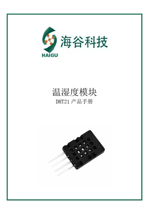
温湿度模块DHT21产品手册一、产品概述本产品是采用高稳定性电容式感湿元件作为传感元件,经过微处理器采集处理转化成数字信号输出。
每一个传感器都经过标定校准和测试。
具有长期稳定、可靠性高、精度高、低功耗等特点。
二、尺寸图单位:mm(±0.5)三、产品特点DHT21数字温湿度模块具有以下特点:1、数字输出,单总线协议,通信距离支持100米;2、超低功耗;3、0-100%相对湿度测量范围;4、全标定、温漂校准。
5、使用独立感湿元器件,稳定性好,抗污染能力强四、性能特征相对湿度温度五、电气特性参数条件最小典型最大单位供电电压VDD 2.83.3 5.5V 供电电流休眠模式0.2uA 测量模式500uA 采样周期 2.0S低电平输出电压Io<4mA 0250mV 高电平输出电压Rp<25kΩ80%100%VDD 低电平输入电压下降沿0%20%VDD 高电平输入电压上升沿80%100%VDD 输出电流On 4mA 三态门(Off)1020μA表3Io 表示低电平输出电流Rp 代表上拉电阻参数条件最小典型最大单位分辨率0.1%RH 量程范围099.9%RH 精度25℃±3%RH重复性±0.1响应时间1/e(63%)<8S迟滞±0.5漂移典型值<3%RH/r 参数条件最小典型最大单位分辨率0.1℃工作范围-4080℃精度±0.5℃重复性±0.2℃响应时间1/e(63%)1S迟滞±0.1漂移典型值<0.2℃/r图1图2表1表2六、用户指南1、引脚分配引脚名称描述1VDD 电源2.8~5.5V 2SDA 串行数据,双向口3NC NC 4GND 地表4:引脚分配1.1、电源引脚(VDD GND)本产品的供电电压为2.8~5.5V,建议供电电压为3.3V。
1.2、串行数据(SDA)SDA 为数据口,三态结构,SDA 在SCK 时钟下降沿之后改变状态,并仅在SCK 上升沿有效2、通信协议DHT21为了精确测量气体的湿度,减少温度对测量的影响,DHT21传感器在非工作期间,自动转为休眠模式,以降低传感器自身的发热对周围气体湿度的影响。
湿度与温度传感器产品说明书

• Measuring range from 5 to 95 %HR and from 0 to 50 °C (1) or from -20 to +80 °C (2)• 0-10 V output, active, power supply24 Vac/Vdc (3-4 wires) or 4-20 mAoutput, passive loop, power supply from 16 to 30 Vdc (2 wires)• Housing with simplified mounting system• ABS V0 housing IP65(2) or IP20(1), with orwithout display • Alternating display of humidity and temperature • “¼ turn” system mounting with wall-mount plateFeatures of housingPart numberPower supply / Output A : Active 24 Vac/Vdc – 0-10 V P : Passive – 16/30 Vdc - 4-20 mA Display O : With display N : Without displayType of probe S : Ambient A : Duct D : Remote ES : StandardExample: TH 110-ANSHumidity and temperature transmitter TH 110, 0-10 V active, without display, ambient model.Caution: the TH 110 – POES model (passive with display) is not availableConfigurable outputs1 or2 analogue outputs(1)Ambient model / (2) Duct, remote and standard model.Ambient modelDuct modelProbe cable length (remote models only)( ): 2 m 05M: 5 m 10M: 10 mStandard modelTechnical specificationsConnectionsInside the front housing 1. Active switch (S1)2. Inactive switch3. LCC-S software connection4. Output terminal block5. Power supply terminal block6.Cable glandSimplified calibrationElectronic board and measuring element connected to the front side of the sensor, which allows toconfigure and calibrate your device without causing any damage.12Removable front face Fixed back housingGeneral features*Can be configured by switch.**All the accuracy indicated in this technical datasheet were stated in laboratory conditions, and can be guaranteed for measurements carried out in the same conditions, or carried out with calibration compensation.Measuring range Analogue output*654316354(standard model)Electrical connections as per NFC15-100 standardsThis connection must be made by a qualified and trained technician.IRH Vdc IT Vdc 1 2 hilos - +- +IRH Vdc IT Vdc IRH VdcIT Vdc IRH VdcIT Vdc symbol:F T _E N – T H 110 – 06/01/23 – N o n -c o n t r a c t u a ld o c u me n t – W e r e s e r v e t h e r i g h t t o m o d if y t h e c h a r a c t e r i s t i c s o f o u r p r o d u c t s w i t h o u t p r i o r n o t i c e .Only the accessories supplied with the device must be used.T o configure the transmitter , it must not be energized. Then, you can make the settings required, with the DIP switches (as shown on the drawing below).When the transmitter is configured, you can power it up.Please follow carefully the combinations beside with the DIP switch. If the combination is wrongly done, the following message will appear on the display of the transmitter “CONF ERROR”. In that case, you will have to unplug the transmitter , place the DIP switches correctly, and then power the transmitter up.1234Off OnActive switchUnit settingOutput setting On-off switch1234Active switch (S1)Please refer to the user manual of the LCC-S software to make the configuration.Set the DIP switches as shown beside. Connect the cable of the LCC-S to the connection of the transmitter .PC configurationSettings and use of the transmitterIt is possible to set the measuring ranges and the unit of the instrument either by switch and/or via software.Configurationis correctly installed. Ambient model does not have any mounting plate. 4 fixing holes are present inside the back Configuration via LCC-S software (option)It is possible to configure intermediate ranges, an offset...Example: for a 0-100 °C transmitter, minimum delta is 20 °C.The instrument can be configured from 0 to +20 °C or from -10 to +10 °C. In order to compensate a possible drift of the sensor, it is possible to add an offset to the displayed value by the TH 110 transmitter: it shows 48% RH, a standard instrument shows 45% RH. It is then possible, via the software, to integrate an offset of -3 to the displayed value by the TH 110 instrument.The configuration of the parameters can be done either with the DIP switch or via software (you can not combine both solutions).WarrantyInstruments have 1-year guarantee for any manufacturing defect.Maintenance:• Avoid any aggressive solvent.• Protect the transmitter and its probes from any cleaning product containing formalin, that may be used for cleaning rooms or ducts.Precautions for use: always use the device in accordancewith its intended use and within parameters described in the technical features in order not to compromise the protection ensured by the device.。
dht11使用手册
dht11使用手册DHT11是一款常用的温湿度传感器,它能够测量并监测环境中的温度和湿度。
以下是关于DHT11的使用手册,希望能够帮助您更好地使用这款传感器。
一、简介DHT11是一款由AM2301温湿度传感器和数字模块构成的测温湿度模块。
它采用单总线通信方式,能够同时测量环境中的温度和湿度,具有测量精度高、稳定性好等优点。
DHT11的使用非常方便,只需将其连接到单片机的某个I/O口即可。
二、使用步骤1.硬件连接将DHT11的VCC引脚连接到单片机或开发板的+5V电源,GND引脚连接到地线,OUT引脚连接到单片机的I/O口(推荐使用GPIO)。
2.初始化在开始数据读取之前,需要先对DHT11进行初始化。
将I/O 口初始化为输出模式,然后输出低电平(0)至少18ms,再输出高电平(1)并保持60-400us。
此时DHT11会响应并开始工作。
3.数据读取初始化完成后,DHT11会自动开始测量环境中的温度和湿度。
等待40ms后,DHT11会自动将测量到的数据通过I/O口发送给单片机或开发板。
单片机或开发板可以通过读取I/O口的状态来获取数据。
4.数据解析从DHT11读取的数据是一个8位的湿度数据和一个8位的温度数据,需要对其进行解析才能得到实际的湿度和温度值。
根据DHT11的通信协议,我们可以使用以下公式来计算湿度和温度值:湿度值= (湿度数据×10) % 100 温度值= (温度数据/10) + 25三、注意事项在使用DHT11时,需要注意以下几点:1.DHT11的VCC引脚电压应保持在4.5-5.5V之间。
2.在读取数据时,需要等待一定的时间以保证数据传输的稳定。
通常情况下,建议等待大约80-200ms。
3.如果连续读取几次数据都失败,可能需要重新初始化DHT11。
4.在连接DHT11时,需要保证OUT引脚处于低电平状态。
如果OUT引脚处于高电平状态,可能会导致DHT11无法正常工作。
5.DHT11的工作环境温度应保持在0-50℃之间,如果环境温度过高或过低,可能会导致测量值不准确。
温湿度传感器AM2301B产品手册说明书
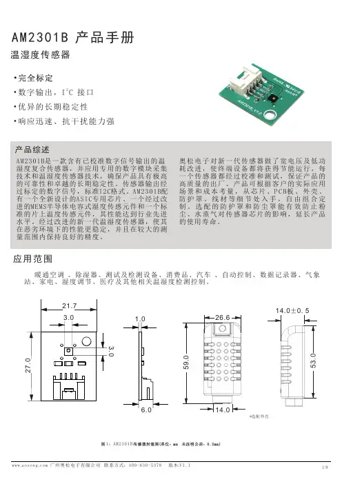
温湿度传感器应用范围暖通空调 、除湿器、测试及检测设备、消费品、汽车 、自动控制、数据记录器、气象站、家电、湿度调节、医疗及其他相关温湿度检测控制。
2• 数字输出,I C 接口• 优异的长期稳定性• 响应迅速、抗干扰能力强1:AM2301BAM2301B 产品手册*选配外壳1.0电子对新一代传感器做了宽电压及低功59.026.614.014.0±0.553.0此精度为出厂检验时,传感器在 25℃供电电压为3.3V 条件下的测试精度。
此数值不包括迟滞和非线性,并只适用于 非冷凝条件。
25℃和1m/s 气流条件下,达到一阶响应 63%所需时间。
正常工作范围:0-80%RH, 超出此范围,传感器读数会有偏差(在90%RH 湿度下 200 小时后,漂移<3%RH)。
如果传感器周围有挥发性溶剂、带刺激性气味的胶带、粘合剂以及包装材料,读数可能会偏高。
详细说明请参阅相关文件。
供电电流和功耗的最小值和最大值都是基于 V CC = 3.3V 和 T<60℃的条件。
平均值为每两秒中进行一次测量的数值。
响应时间取决于传感器基片的导热率。
123456传感器性能相对湿度温度±0±2±4±6±8±10图 2 25°C 时相对湿度的最大误差。
△R H (%RH )相对湿度(%RH )电气特性表2 电气特性。
表 1 湿度特性表表 3 温度特性表-40 -20 0 20 40 6080图 3 温度典型误差和最大误差。
温度(℃)△T℃包装信息表4 包装信息。
图6V CC =3.3V 时,典型的供电电流与温度的关系曲线(休眠模式)。
请注意,这些数据与显示值存在大约±25%偏差。
2.1 2.3 2.5 2.7 2.93.1 3.3 3.5电压(V CC )1 扩充性能10080604020图4工作条件温度(℃)5101520253035404550556065707580温度( ℃)图50~80℃范围内对应的湿度最大误差,单位:(%RH)相对湿度(%)范围最大范围常正电流(n A )电流I C C (n A )温度(℃)请注意:以上误差为以高精度露点仪做参考仪器测试的最大误差(不包括迟滞)。
DHT22课程设计

DHT22课程设计一、课程目标知识目标:1. 学生能理解DHT22温湿度传感器的原理与结构;2. 学生能掌握DHT22传感器与微控制器(如Arduino)的连接方法;3. 学生能掌握读取DHT22传感器数据并进行简单处理的方法。
技能目标:1. 学生能运用DHT22传感器进行环境温湿度的实时监测;2. 学生能通过编程实现DHT22传感器数据的读取和处理;3. 学生能运用所学的知识解决实际生活中的温湿度监测问题。
情感态度价值观目标:1. 学生培养对物联网技术的兴趣,激发探究科学技术的热情;2. 学生通过实践活动,培养团队合作意识,增强问题解决能力;3. 学生认识到温湿度监测在生活中的重要性,提高环保意识。
课程性质:本课程为信息技术课程,结合物理知识与编程技能,注重实践操作。
学生特点:六年级学生具备一定的物理知识和编程基础,对新鲜事物充满好奇心。
教学要求:课程要求学生动手实践,注重培养学生的实际操作能力和创新思维。
通过本课程的学习,学生能够将理论知识应用于实际情境,解决实际问题。
教学过程中,将目标分解为具体的学习成果,以便进行教学设计和评估。
二、教学内容1. 理论知识:- 介绍DHT22温湿度传感器的原理与结构;- 讲解温湿度监测在生活中的应用及重要性;- 概述传感器与微控制器(Arduino)的连接方式。
2. 实践操作:- 演示DHT22传感器与Arduino的连接方法;- 教授如何使用编程环境(如Arduino IDE)读取DHT22传感器数据;- 指导学生进行数据处理,实现温湿度实时监测。
3. 教学大纲:- 第一课时:介绍DHT22传感器原理、结构及应用场景;- 第二课时:讲解DHT22传感器与Arduino的连接方法;- 第三课时:学习编程读取DHT22传感器数据并进行处理;- 第四课时:实践活动,学生分组进行温湿度监测项目设计。
4. 教材章节:- 第六章:传感器及其应用;- 第七章:微控制器编程与物联网应用。
温湿度传感器产品说明书

特点:湿敏电阻(湿敏传感器)是在导电半导体陶瓷基片上涂履一层高分子感湿膜,与空气中相对湿度变化导致电阻值系数变化原理。
应用于数字式温湿度表、电子温湿度计、加湿机、抽湿机、空调、气象测量场合。
优点:具有良好的灵敏感应特性、防水性、稳定性、高精度、低飘移,工业级,可替代日本韩国等同类进口产品。
SHR01-313K特点:湿敏电阻(湿敏传感器)是在导电半导体陶瓷基片上涂履一层高分子感湿膜,与空气中相对湿度变化导致电阻值系数变化原理。
应用于数字式温湿度表、电子温湿度计、加湿机、抽湿机、空调、气象测量场合。
优点:具有良好的灵敏感应特性、防水性、稳定性、高精度、低飘移,工业级,可替代日本韩国等同类进口产品。
特点:湿敏电阻(湿敏传感器)是在导电半导体陶瓷基片上涂履一层高分子感湿膜,与空气中相对湿度变化导致电阻值系数变化原理。
应用于数字式温湿度表、电子温湿度计、加湿机、抽湿机、空调、气象测量场合。
优点:具有良好的灵敏感应特性、防水性、稳定性、高精度、低飘移,高性价比,可替代日本神荣、北陆、韩国等同类进口产品。
SHR02-313K特点:湿敏电阻(湿敏传感器)是在导电半导体陶瓷基片上涂履一层高分子感湿膜,与空气中相对湿度变化导致电阻值系数变化原理。
应用于数字式温湿度表、电子温湿度计、加湿机、抽湿机、空调、气象测量场合。
优点:具有良好的灵敏感应特性、防水性、稳定性、高精度、低飘移,高性价比,可替代日本神荣、北陆、韩国进口等同类产品。
特点:湿敏电阻(湿敏传感器)是在导电半导体陶瓷基片上涂履一层高分子感湿膜,与空气中相对湿度变化导致电阻值系数变化原理。
应用于数字式温湿度表、电子温湿度计、加湿机、抽湿机、空调、气象测量场合。
优点:具有良好的灵敏感应特性、防水性、稳定性、高精度、低飘移,高性价比,可替代日本神荣、北陆、韩国进口等同类产品。
特点:电容式温湿度模块是将湿度传感器非线性电阻值转换为线性电压信号输出,体积小,使用方便,精度高。
AM2303
高温型数字温湿度传感器 AM2303
►相对湿度和温度测量 ►全部校准,数字输出 ►卓越的长期稳定性 ►无需额外部件 ►超长的信号传输距离 ►超低能耗 ►4 引脚安装 ►完全互换
AM2303产品概述 AM2303数字温湿度传感器是一款含有已校准数字信号输出的温湿度复合
传感器。它应用专用的数字模块采集技术和温湿度传感技术,确保产品具有极 高的可靠性与卓越的长期稳定性。传感器包括一个电容式感湿元件和DS18B20 感温器件,并与一个高性能8位单片机相连接。因此该产品具有品质卓越、超 快响应、抗干扰能力强、性价比极高等优点。每个AM2303传感器都在极为精 确的湿度校验室中进行校准。校准系数以程序的形式储存在OTP内存中,传感 器内部在检测信号的处理过程中要调用这些校准系数。单线制串行接口,使系 统集成变得简易快捷。超小的体积、极低的功耗,信号传输距离可达20米以上 , 使其成为各类应用甚至最为苛刻的应用场合的最佳选则。产品为 4 针单排引 脚封装。连接方便,特殊封装形式可根据用户需求而提供。
广州奥松电子有限公司
3
数字温湿度传感器 AM2303
图2 高电平后就是数据位,每1bit数据都是由一个低电平时隙和一个高电平组 成。低电平时隙就是一个50us左右的低电平,它代表数据位的起始,其后的高电 平的长度决定数据位所代表的数值,较长的高电平代表1,较短的高电平代表0。 共40bit数据,当最后一Bit数据传送完毕后,从机将再次拉低总线50us左右,随 后释放总线,由上拉电阻拉高。 数字1信号表示方法如图4所示:
用户主机(MCU)发送一次开始信号后,AM2303从低功耗模式转换到高速 模式,等待主机开始信号结束后,AM2303发送响应信号,送出40bit的数据,并触发 一次信号采集。(注:主机从AM2303读取的温湿度数据总是前一次的测量值, 如两次测量间隔时间很长,请连续读两次以获得实时的温湿度值)
DHT11 温湿度传感器说明书
DHT11说明书温湿度传感器●具有抗冲击性及电气性能优良●完全标定●数字输出,单总线通讯●优异的长期稳定性●响应迅速、恢复时间快、抗干扰能力强产品简述DHT11是一款含有已校准数字信号输出的温湿度复合传感器,采用了自主研发的集成式数字温湿度元件,应用专用的数字模块采集技术和温湿度传感技术,确保产品具有极高的可靠性与卓越的长期稳定性。
DHT11传感器内包含一个温湿度测量元件和一个高性能MCU。
应用范围DHT11温湿度传感器可以应用于农业、家电、汽车、气象、医疗等领域,如暖通空调、除湿机、冷链仓储、测试及检测设备、数据记录仪、湿度调节系统、医疗等。
图1.DHT11温湿度传感器1.传感器性能1.1相对湿度表1.湿度特性表参数测试条件最小典型最大单位量程范围附加说明15-95%RH精度2--±5%RH重复性--±1-%RH互换性-完全互换响应时间3τ(63%)-<6-s迟滞--±0.3-%RH漂移4典型值-<0.5-%RH/yr 1.2电气特性表2.电气特性表符号参数测试条件最小典型最大单位VCC供电电压- 3.35 5.5VI平均电流5休眠-60-µA 测量-1000-µAV OL低电平输出电压I L6=5mA0-300mVV OH高电平输出电压Rp<25kΩ0.9*VCC-VCC VV IL低电平输入电压下降0-0.3VV IH高电平输入电压上升0.7-VCC VRp上拉电阻7VCC=5V1 4.7100kΩT S采样周期-2--s实际使用中的一些特性如功耗、输入和输出的高、低电平电压等都取决于供电电压。
在使用传感器时,要使系统获得鲁棒性,请确保各参数在表2所给出的范围内。
1正常工作范围:8~85%RH,超出此范围,传感器读数会有偏差(在90%RH湿度下60小时后,漂移>3%RH)。
工作范围进一步限定在-20~60℃。
2此精度为传感器出厂检验时,在25℃、VCC=5V条件下的测试精度。
AM2322温湿度传感器STM8S208驱动(更新)
AM2322温湿度传感器STM8S208驱动AM2322温湿度传感器STM8S208驱动该程序测试能用,AM2322产品都是共用一个器件地址0xB8,所以只能挂一个AM2322器件,如果挂两个就有两个相同的器件地址,这样IIC没有办法寻址,但这并不代表不能与其它器件共存,比喻AT24C02,它的器件地址是0xA0,它们可以在同一条IIC部上面工作的。
AM2322温度采集成功后,得到高8位和低8位的数据。
将其组合成一个16位的值,再换算成十进制的温湿值,该值是实际值的10倍,除以10后就是正确温湿度值了。
例如:采集到的湿度值为:高8位是0x03 低8位是0x39,组合成16位的值就是0x0339,换算成十进制是825,再除以10就是82.5,表示相对湿度82.5%,温度值也是这样计算。
该程序采用模拟IIC通讯,总共有四个文件:IIC.c、IIC.h、AM2322.c、AM2322.h,在工程新建这四个文件依次添加以下代码:在IIC.c文件中添加以下代码(通用的IIC底层驱动):void I2C_Configuration()//初始化IIC端口{GPIO_Init(I2C_PORT, I2C_SCL_PIN, GPIO_MODE_OUT_PP_HIGH_SLOW);GPIO_Init(I2C_PORT, I2C_SDA_PIN, GPIO_MODE_OUT_PP_HIGH_SLOW);}//产生IIC起始信号void IIC_Start(void){I2C_SDA_OUT; //sda线输出I2C_SDA_H;I2C_SCL_H;delay_us(14);I2C_SDA_L;//开始:当SCL为高时,数据从高到低变化delay_us(14);I2C_SCL_L;//钳住I2C总线,准备发送或接收数据}//产生IIC停止信号void IIC_Stop(void){I2C_SDA_OUT;//sda线输出I2C_SCL_L;I2C_SDA_L;//停止:当SCL为高时,数据从低到高变化delay_us(14);I2C_SCL_H;delay_us(14);I2C_SDA_H;//发送I2C总线结束信号}//等待应答信号到来//返回值:1,接收应答失败// 0,接收应答成功u8 IIC_Wait_Ack(void){u8 ucErrTime=0;I2C_SCL_L;I2C_SDA_H;I2C_SDA_IN; //SDA设置为输入delay_us(14);I2C_SCL_H;delay_us(14);while(GPIO_ReadInputPin(I2C_PORT, I2C_SDA_PIN))//等到SDA变低{ucErrTime++;if(ucErrTime>250){IIC_Stop();return 1;}delay_us(1);}I2C_SCL_L;//时钟输出0delay_us(10);return 0;}//产生ACK应答void IIC_Ack(void){ I2C_SDA_OUT;I2C_SCL_L;I2C_SDA_L;delay_us(50);I2C_SCL_H;delay_us(50);I2C_SCL_L;//I2C_SDA_H;}//产生非ACK应答void IIC_NAck(void){ I2C_SDA_OUT;I2C_SCL_L;I2C_SDA_H;delay_us(50);I2C_SCL_H;delay_us(50);I2C_SCL_L;// I2C_SDA_H;}//IIC发送一个字节//返回从机有无应答//1,有应答//0,无应答void IIC_Send_Byte(u8 txd){u8 t;I2C_SDA_OUT;I2C_SCL_L;//拉低时钟开始数据传输for(t=0;t<8;t++){I2C_SCL_L;if((txd&0x80)){I2C_SDA_H;}else{I2C_SDA_L;}txd<<=1;delay_us(15); //延时I2C_SCL_H;delay_us(15);}I2C_SCL_L;}//读1个字节,ack=1时,发送ACK,ack=0,发送nACKu8 IIC_Read_Byte(unsigned char ack){unsigned char i,receive=0;I2C_SDA_IN;//SDA设置为输入for(i=0;i<8;i++ ){I2C_SCL_L;delay_us(50);I2C_SCL_H;delay_us(50);receive<<=1;if(GPIO_ReadInputPin(I2C_PORT, I2C_SDA_PIN))receive++;}I2C_SCL_L;if (!ack)IIC_NAck();//发送nACKelseIIC_Ack(); //发送ACKreturn receive;}在IIC.h中添加以下代码:#ifndef H_I2C_H //宏定义,定义文件名称#define H_I2C_H/*---------------------------头文件引用--------------------------------------*/#include "stm8s.h"//引用STM8头文件#define I2C_SCL_PIN GPIO_PIN_1 //如果将IIC端口换到它引脚只修改这里,其它的不用动#define I2C_SDA_PIN GPIO_PIN_2 //如果将IIC端口换到它引脚只修改这里,其它的不用动#define I2C_PORT GPIOE //如果将IIC端口换到它引脚只修改这里,其它的不用动#define I2C_SCL_L GPIO_WriteLow(I2C_PORT,I2C_SCL_PIN);#define I2C_SCL_H GPIO_WriteHigh(I2C_PORT,I2C_SCL_PIN);#define I2C_SDA_L GPIO_WriteLow(I2C_PORT,I2C_SDA_PIN);#define I2C_SDA_H GPIO_WriteHigh(I2C_PORT,I2C_SDA_PIN);#define I2C_SDA_OUT GPIO_Init(I2C_PORT, I2C_SDA_PIN, GPIO_MODE_OUT_OD_HIZ_FAST);#define I2C_SDA_IN GPIO_Init(I2C_PORT, I2C_SDA_PIN, GPIO_MODE_IN_PU_NO_IT);//以下是函数声明:void I2C_Configuration();void IIC_Start(void);void IIC_Stop(void);u8 IIC_Wait_Ack(void);void IIC_Ack(void);void IIC_NAck(void);void IIC_Send_Byte(u8 txd);u8 IIC_Read_Byte(unsigned char ack);#endif在AM2322.c中添加以下代码:u8 WR_Flag;u8 WriteNByte(unsigned char sla,unsigned char *s)//写数据{IIC_Start();//起始条件IIC_Send_Byte(sla);//发送器件地址IIC_Wait_Ack();//等待ACK响应IIC_Send_Byte(s[0]);//发送字节地址IIC_Wait_Ack();//等待ACK响应IIC_Send_Byte(s[1]);//发送字节地址IIC_Wait_Ack();//等待ACK响应IIC_Send_Byte(s[2]);//发送字节地址IIC_Wait_Ack();//等待ACK响应IIC_Stop(); //执行停止条件return(0);}u8 ReadNByte(unsigned char Sal, unsigned char *p)//接收或叫读数据{IIC_Start();//发送起始条件IIC_Send_Byte(Sal|0x01);//发送器件地址IIC_Wait_Ack();//等待ACK响应delay_us(50);p[0]=IIC_Read_Byte(1);//功能码p[1]=IIC_Read_Byte(1);//数据长度p[2]=IIC_Read_Byte(1);//湿度高8位p[3]=IIC_Read_Byte(1);//湿度低8位p[4]=IIC_Read_Byte(1);//温度高8位p[5]=IIC_Read_Byte(1);//温度低8位p[6]=IIC_Read_Byte(1);//CRC高8位p[7]=IIC_Read_Byte(0);//CRC低8位IIC_Stop();//发送停止条件return 0;//读取的数据返回给函数}void Waken(void) //唤醒器件{IIC_Start(); // 启动I2CIIC_Send_Byte(0xB8); // 发送器件地址IIC_Wait_Ack(); // 唤醒指令时传感器不会回ACK 但是第一定要发检测ACK 的时钟否则会出错delay_ms(1); // 至少延时1个ms说明书里,有个最大值,实际当中你只要大于1MSIIC_Stop();}在AM2322.h中添加以下代码:#ifndef H_AM2322_H //宏定义,定义文件名称#define H_AM2322_H/*---------------------------头文件引用--------------------------------------*/#include "stm8s.h"//引用STM8头文件u8 WriteNByte(unsigned char sla,unsigned char *s);u8 ReadNByte(unsigned char Sal, unsigned char *p);void Waken(void);最后注意要在main.c中引用IIC.h和AM2322.h两个头文件。
湿度与温度传感器数据表说明书
• Measuring range from 5 to95% RH and from 0 to 50 °C(1)or from -20 to 80 °C(2)• 0-10 V output, active, powersupply 24 Vac/Vdc (3-4 wires)or 4-20 mA output, passive loop,power supply from 16 to 30 Vdc(2 wires)• ABS V0 housing IP65(2) or IP20(1),with or without display• Alternating display of humidity andtemperature• “¼ turn” system mounting withwall-mount plate• Housing with simplified mountingsystemFeatures of housingPart numberPower supply / OutputA: Active 24 Vac/Vdc – 0-10 VP: Passive – 16/30 Vac - 4-20 mADisplayO: With displayN: Without displayType of probeS: AmbientA: DuctD: RemoteExample: TH 110 – ANSHumidity and temperature transmitter TH 110,0-10 V active, without display, ambient model.(1) Ambient model / (2) Duct and remote modelDuct model, stainless steel probeProbe cable length (remote models only)( ): cable lentgh 2 m (standard model)05M: cable length 5 m10M: cable length 10 mTechnical specificationsConnectionsInside the front housing 1. Actif switch (S1)2. Inactive switch3. LCC-S software connection4. Output terminal block5. Power supply terminal block6.Cable glandSimplified calibrationElectronic board and measuring element connected to the front side of the sensor, which allows toconfigure and calibrate your device without causing any damage.12Removable front faceFixed back housing6543General features*Can be configured by switch.**All the accuracy indicated in this technical datasheet were stated in laboratory conditions, and can be guaranteed for measurements carried out in the same conditions, or carried out with calibration compensation.Electrical connections NFC15-100This connection must be made by a qualified and trained technician. To make the connection, the transmittermust not be energized.For TH 110-AOS, TH 110-ANS, TH 110-AOD, TH 110-AND,TH 110-AOA, TH 110-ANA models with 0-10 V output – active:For TH 110-POS, TH 110-PNS, TH 110-POD, TH 110-PND, TH 110-POA, TH 110-PNA models with 4-20 mA output – passive:To make a 3-wire connection, before powering up the transmitter, please connect the output ground to theinput ground. See drawing below.IRH VdcIT Vdc IRH VdcIT Vdc VT GND VRH VT GND VRH1 2 3 4 56 7 + - +- +1 2 3 4 5 6 7- +- +or IRH VdcIT Vdc 1 2 3 4 5 6 7- +- +IRH VdcIT Vdc 2 wiresSymbols usedFor your safety and in order to avoid any damage of the device, please follow the procedure described in this document and read carefully the notes preceded by the following symbol:The following symbol will also be used in this document, please read carefully the information notes indicated after this symbol:VT GND VRH+-IRH Vdc IT Vdc IRH Vdc IT VdcF T _E N – T H 110 – 15/01/2021– N o n-c o n t r a c t u a l d o c u m e n t – W e r e s e r v e t h e r i g h t t o m o d i f y t h e c h a r a c t e r i s t i c s o f o u r p r o d u c t s w i t h o u t p r i o r n o t i c e .Only the accessories supplied with the device must be used.T o configure the transmitter , it must not be energized. Then, you can make the settings required, with the DIP switches (as shown on the drawing below). When the transmitter is configured, you can power it up.Please follow carefully the combinations beside with the DIP switch. If the combination is wrongly done, the following message will appear on the display of the transmitter “CONF ERROR”. In that case, you will have to unplug the transmitter , place the DIP switches correctly, and then power the transmitter up.1234Off OnActive switchUnit settingOutput setting On-off switch1234Active switch (S1)Please refer to the user manual of the LCC-S software to make the configuration.Set the DIP switches as shown beside.Connect the cable of the LCC-S to the connection of the transmitter.PC configurationSettings and use of the transmitterIt is possible to set the measuring ranges and the unit of the instrument either by switch and/or via software.ConfigurationAmbient model does not have any mounting plate. 4 fixing holes are present inside the back housing. Use them to install the transmitter on the required location.Configuration via LCC-S software (option)It is possible to configure intermediate ranges, an offset...Example: for a 0-100 °C transmitter, minimum delta minimum is 20 °C. The instrument can be configured from 0 to +20 °C or from -10 to +10 °C. In order to compensate a possible drift of the sensor, it is possible to add an offset to the displayed value by the TH110 transmitter: it shows 48% RH, a standard instrument shows 45% RH. It is then possible, via the software, to integrate an offset of -3 to the displayed value by the TH 110 instrument. The configuration of the parameters can be done either with the DIP switch or via software (you can not combine both solutions).Maintenance:• Avoid any aggressive solvent.• Protect the transmitter and its probes from any cleaning product containing formalin, that may be used for cleaning rooms or ducts.Precautions for use: always use the device in accordancewith its intended use and within parameters described in the technical features in order not to compromise the protection ensured by the device.WarrantyInstruments have 1-year guarantee for any manufacturing defect.。