
IPG大功率光纤激光器 内部普及版(独家)
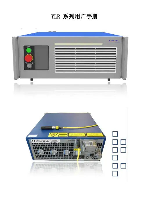
光纤激光器外观
光纤
QBH
光纤激光的传输原理
光纤是一种高度透明的玻璃丝,由纯石英经复杂的工艺拉制而成。 光纤中心部分(芯Core)+同心圆状包裹层(包层Clad)+涂覆层
包层 芯
树脂被覆层
特点:ncore>nclad 光在芯和包层之间的界面上反复进行全反射,并在光纤中传递下去。
光纤结构图
套层 外包层 纤芯 一次涂覆层
激光模块的组合
+
+
+
+
= xxx kW
Modular Multi-KW Fiber Laser Very High Beam Quality
激光模块的监控
功率显示
模块温度显示 模块选择显示
激光模块电源
激光模块电源
电源状态监控
电源状态显示
典型制冷机组
连接方式
IPG标配的两种制冷机
IPG WW chiller
YLR-xx- yy-WW series
YLR-xx- yy-QCW series
S2(4,6)-xx series, remote BS
C2-xx series, remote FFC
WA-xx series, remote WA chiller
WW-xx series, remote WW chiller
Multimode Fiber Laser with internal 2-ways Beam Switch on top
内置两路光闸
P ≥ 3000 W
YLR-2000-S2T-QCW Fiber Laser
Peak Peak Power Power (@ (@ workpiece) workpiece) Wave Wave Length: Length: Internal Internal 2-ways 2-ways BS BS installed installed Feeding Feeding Fiber Fiber Diameter Diameter 50 50 µm µm Process Process Fiber Fiber Diameter Diameter 100 100 µm µm Process Process Fiber Fiber Length Length BPP BPP Footprint Footprint Hight Hight Power Power Consumption Consumption Wall Wall Plug Plug Efficiency Efficiency up up to to 50m 50m 3 3 mm mm x x mrad mrad 856 856 x x 806 806 mm mm 1186 1186 mm mm max. max. 7 7 kW kW ~ ~ 30 30 % % 1070 1070 nm nm 4.0 4.0 kW kW
Power Power Consumption Consumption max. max. 70 70 kW kW Wall ~ 30% 30% Wall Plug Plug Efficiency Efficiency ~ Weight 1200 Weight 1200 kg kg
YLR-xx-C series specifications
LCI-170.01-W-3, LCI-171.01-W-3 IHE-170.00-W-3, LC-170.01-A-3-5
PC 160.01-NZ-DIS, PC 160.01-NZW-DIS
5
20.0
PC 160.01-NZ-DIS, PC 160.01-NZW-DIS
6
24.0
LC 260.01-A-3-5
IPG高功率光纤激光器
The Power
to Transform
TM
内部普及版
典型的高功率光纤激光加工系统
典型的高功率光纤激光加工系统一般包括以下几个基本单元:
高功率光纤激光器系统 准直与聚焦系统 运动机构 控制系统 辅助系统
高功率光纤激光器的典型应用
传输光纤 操作光纤
机械手
PC 250.01-NZ-DIS, PC 250.01-NZW-DIS PC 250.01-NZ-DIS, PC 250.01-NZW-DIS PC 400.01-NZ-DIS, PC 400.01-NZW-DIS
10 15
38.0 54.0
激光器有关制冷机的接口
制冷机接口
制冷机接口信号说明
激光器的几种运行模式
100um
150um及以上
光闸
多路输出
光闸的光学原理图
反射镜
Feeding fiber
准直镜 耦合镜
Process fiber fiber Process
光闸的种类
型号: 描述 FFS 2way 操作光纤的 数目: 2way; 4way; 6way
含义 两路光闸,传输光纤接头类型为QB,操作光纤接头类 型分别为QB和QD。
IPG Chiller
Volume 0.3 m3
Riedel Chiller
Volume 2.1 m3
激光器功率 (KW) 1 2 4
水冷机要求制冷量 (KW) 4.0 8.0 16.0
可用水冷机
PC 41.02-KE-S, PC 41.02-KEW-S PC 63.02-KE-S, PC 63.02-KEW-S
*Output power 5 kW on special request
YLR-xx-SM-CT series specifications
Single Mode Fiber Laser with internal Fiber/Fiber coupler on top
内置光光耦合器
YLR-20000 Fiber Laser
QB传输光 纤类型 :QB
QB 操作光 纤类型 :QB, QD
ES 分能量 切换, 空白时 表示分 时间切 换
M=1.2 放大率 :0.8~ 2.0
型号举例 FFS 2way QB-QB/QD, M=1.2
FFS 4way QB-QB, 2ES M=1.2
四路光闸,其中两路为分时间切换,另两路为分能量切 换
内置两路光闸
YLR-xx-CT series specifications
Multimode Fiber Laser with internal Fiber/Fiber coupler on top 内置光光耦合器
P ≤ 2500 W
P ≥ 3000 W
YLR-xx-ST2(SST2) series specifications
光纤(fiber)
型号 QB QD 描述 IPG最常用型号 欧洲汽车工业标准 芯径 50-1000 µm 50-1000 µm 长度 5-200 m 5-200 m 最小弯曲半径 200mm 200mm 最小盘绕半径 300mm 300mm 数值孔径 0.2 0.2
光光耦合器
输入端 输入端
输出端 输 出端
全光纤激光模组
LDM# LDM#
• • • • • • • • • •
-
体积小巧,高度集成的全光纤设计 体积小巧,高度集成的全光纤设计 并联单芯结二极管激光模块组合 并联单芯结二极管激光模块组合 侧面泵浦 侧面泵浦 坚固的机械结构,耐冲击稳定性及强 坚固的机械结构,耐冲击稳定性及强 超高的温度稳定性 超高的温度稳定性
光光耦合器的光学原理图
Feeding fiber
光学镜片
Process fiber
激光束
当前光光耦合器类型
输入端 名称 传输光纤 (feeding fiber) 输出端 操作光纤(process fiber) 或二级传输光纤
激光功率不大于4KW时可 选光纤芯径 通常光纤芯径
50um
100um及以上
Output Output Power Power (@ (@ workpiece workpiece ) ) Wave Wave Length Length Fiber Fiber Diameter Diameter Fiber Fiber Length Length BPP BPP Footprint Footprint Hight Hight 1070 1070 nm nm 100 100 µm µm up up to to 10m 10m < <5 5 mm mm x x mrad mrad 1480 1480 x x 806 806 mm mm 1.500 1.500 mm mm > > 20.0 20.0 kW kW
YLR – 3000(5000) - SM Fiber Laser
Output Output Power Power (@ (@ workpiece) workpiece) Wave Wave Length Length Fiber Fiber Length Length
2 M M2
3.0* 3.0* kW kW
准直聚焦系统
外部光闸
高功率光纤激光器系统
高功率光纤激光器系统包括以下几个模块:
传输光纤/操作光纤 光闸/光光耦合器 激光模块 激光模块电源 制冷机组 控制接口 监控软件
典型光纤激光器系统
IPG光纤激光器内部结构
IPG光纤概述
光纤的外型 光纤的功能 光纤的结构 激光传输的机理 可提供光纤的连接头形式 可提供的光纤芯径及长度
Main advantage: better cutting quality and faster speed
IPG Application Lab in Burbach
Mikro/Makro Cutting Mikro/Makro Welding Hybrid Welding Remote Welding Marking
光纤激光器哪家的好,激光器品牌哪个好

光纤激光器哪家好,激光器品牌哪个好随着激光技术的不断发展,激光应用已经渗透到科研、产业的各个方面,在汽车制造、航空航天、钢铁、金属加工、冶金、太阳能以及医疗设备等领域都起到重要作用。
激光设备的核心就是激光器,我国各大激光设备企业不断地加大技术开发投入,虽然已经取得了一定的成就,各种激光设备实现国产化,达到国际领先水平,但是在主力激光器,超大功率激光器依然依赖进口,以致激光设备价格大幅度上涨,制约了我国激光加工产业的发展,另一方面,国外不少的激光加工企业看准中国激光加工的广大市场前景,纷纷入驻我国的沿海城市,冲击我国激光加工产业,国际竞争国内化。
光纤激光器哪家的最好下面总结目前市场上应用于工业制造领域的激光器主要企业,光纤激光器品牌:国内的是锐科、创鑫,国外的有美国相干,IPG,SPI,通快,JK laser (GSI的品牌子公司)等等,从质量上看,进口的光纤激光器比国产的要好些,而价格方面也贵些,主要看你们公司的预算在什么范围,对光纤激光器的出光率和耐用度有什么要求,需要根据自身设备来选择,适用就好!以供想采购激光焊接、激光切割、激光打标等企业提供相应的参考.排名不分先后。
美国光纤激光器哪家的好——相干(Coherent)公司相干公司成立于1966年,是世界第一大激光器及相关光电子产品生产商,产品服务于科研、医疗、工业加工等多个行业;秉承40年的激光制造经验和创新精神,致力于提供一流的商业化激光器,促进科学研究不断进步、生产制造行业生产力和加工精度的不断提高;其全球化的销售、客户服务和技术支持网络更为客户提供全球范围内的合作和服务。
相干公司能够提供更全面的激光器和激光参数测量产品,包括:氩/氪离子激光器、CO2激光器(10.6μm、9.4μm、调Q、可调谐、单频、THz源)、半导体激光器(375nm、405nm、635nm、780-980nm)、钛宝石连续可调谐激光器、准分子激光器、脉冲染料激光器、钛宝石超快激光器及放大器、半导体泵浦固体激光器(1064nm、532nm、355nm、266nm)、功率计、能量计、光束质量分析仪和波长计等。
什么是光纤激光器

什么是光纤激光器——激光英才网光纤激光器是指用掺稀土元素玻璃光纤作为增益介质的激光器,光纤激光器可在光纤放大器的基础上开发出来:在泵浦光的作用下光纤内极易形成高功率密度,造成激光工作物质的激光能级“粒子数反转”,当适当加入正反馈回路(构成谐振腔)便可形成激光振荡输出。
光纤激光器的类型按照光纤材料的种类,光纤激光器可分为:1.晶体光纤激光器。
工作物质是激光晶体光纤,主要有红宝石单晶光纤激光器和nd3+:YAG单晶光纤激光器等。
2.非线性光学型光纤激光器。
主要有受激喇曼散射光纤激光器和受激布里渊散射光纤激光器。
3.稀土类掺杂光纤激光器。
光纤的基质材料是玻璃,向光纤中掺杂稀土类元素离子使之激活,而制成光纤激光器。
4.塑料光纤激光器。
向塑料光纤芯部或包层内掺入激光染料而制成光纤激光器。
光纤激光器的优势光纤激光器作为第三代激光技术的代表,具有以下优势:(1)玻璃光纤制造成本低、技术成熟及其光纤的可饶性所带来的小型化、集约化优势。
(2)玻璃光纤对入射泵浦光不需要像晶体那样的严格的相位匹配,这是由于玻璃基质Stark 分裂引起的非均匀展宽造成吸收带较宽的缘故。
(3)玻璃材料具有极低的体积面积比,散热快、损耗低,所以上转换效率较高,激光阈值低。
(4)输出激光波长多:这是因为稀土离子能级非常丰富及其稀土离子种类之多。
(5)可调谐性:由于稀土离子能级宽和玻璃光纤的荧光谱较宽。
(6)由于光纤激光器的谐振腔内无光学镜片,具有免调节、免维护、高稳定性的优点,这是传统激光器无法比拟的。
(7)光纤导出,使得激光器能轻易胜任各种多维任意空间加工应用,使机械系统的设计变得非常简单。
(8)胜任恶劣的工作环境,对灰尘、震荡、冲击、湿度、温度具有很高的容忍度。
(9)不需热电制冷和水冷,只需简单的风冷。
(10)高的电光效率:综合电光效率高达20%以上,大幅度节约工作时的耗电,节约运行成本。
(11)高功率,目前商用化的光纤激光器是六千瓦。
高功率光纤激光器原理和应

光纤激光器原理
Laser (Light amplification by the stimulated emissioLDM#
LDM#
LDM# LDM# LDM#
-
有源光纤
+
LDM# LDM# LDM#
• 光纤输出端(connector)与插入式连接头(bayonet)形成电子回 路,可有效监控光纤的状态。
• 光纤输出端有水循环冷却装置,可有效带走激光传输及反射所产 生的热量,保证光纤输出端的安全。
• 在激光器中,有探测器对激光反射进行监控,一旦反射强度超过 阈值,激光器将会报警,避免持续高反,损坏光纤或激光器。
光纤模组
全光纤激光模组
LDM#
LDM#
LDM#
-
注意事项
• 开关机顺序 • 不同季节的注意事项 • 日常保养的注意事项 (激光器,水冷机,空调) • Chiller Tune 软件使用 • LaserNet使用
FFBD
FFBD
Interlock
Interlock.jpg
IPG 光纤概述
1. 光纤外型 2. 光纤原理 3. 光纤结构 4. 光纤型号 5. 最小弯曲半径与盘绕半径 6. 光纤如何实现自我保护
1 光纤外形
2 光纤的原理
光纤是一种高度透明的玻璃丝,由纯石英经复杂的工艺拉制而成。 光纤→中心部分(芯Core)+同心圆状包裹层(包层Clad)+涂覆层
特点:ncore>nclad ⇒光在芯和包层之间的界面上反复进行全反射,并在光纤中传递下 去
3 光纤的结构
4 光纤的型号
5 在有应力(Stressed)与无应力( Unstressed)状况下最小弯曲半径的 区别
IPG振镜使用总结4-25

目录一、组成部分介绍 (2)1.控制主机介绍 (3)2.控制块介绍 (5)二、安装布局 (6)1.主机安装尺寸 (6)2.安装布局 (6)三、接线图 (7)IPG振镜一、组成部分介绍振镜由控制主机、控制块以及振镜头三个部分组成。
(图片为一楼展厅4工位现场图)1.控制主机介绍1端口:24V供电端,自带插头,需配线,接到控制柜24V端子排:4X0.75mm2;A2:+24V, A3:0V;A4:+24V ,A5:0V;A1保留。
2端口:网口,需配网线,连接到上位机PC端,需在PC端安装相应的软件,购买振镜时软件存在配套的U盘里面;具体安装使用见《IPG HP Scanner 简明使用手册》文档。
通过软件与PC端连接时,振镜主机IP地址自动分配,可以不需要设置;3端口:控制主机连接到振镜控制块SCAN端,自带连接线缆(振镜内部连接)4端口:15PIN,激光器控制端,需配线和配插头(主机端为公头,配线时要用母头),需要配两根线缆。
注意:1.9引脚为模拟量控制端口,需要用屏蔽双绞线;3引脚红光控制不接,振镜本身有一个红光需要控制,再控制激光器导引红光不方便操作,还是用PLC来控制导引红光。
即接:1.2.4.5.9.10.11.12引脚即可,其他引脚不接。
接头的金属外壳焊一根线接到激光器XP4 PE针脚。
线缆1:2.4.5.10.11.12(6芯);线缆2:1.9.模拟量信号地(3芯)5端口:控制主机连接到振镜头,自带连接线缆,该线缆标配3M,加长款5M(振镜内部连接)。
6端口:RS232通讯端口,不接线2.控制块介绍SCAN INTERFACE端与控制主机3端口连接,自带线缆(振镜内部连接)ROBOT INTERFACE端与PLC连接信号交互,自带插头,需配线1.2.13.14.23.24都要接0V, 21、22接24V。
组选择3-11相当于激光器的程序号码,根据组选择输入调用振镜控制软件上的组号。
3-11引脚根据实际需要的组数接对应数量的线缆,可以不需要全部接线。
YLR-11使用指南20111105
应用方向: z 生产应用 z 科学研究
系统配置
IPG 的YLR 系列激光器提供了许多系统配置。本使用说明是所有型号的通用说明书。因此,某些型号的特殊设计并 没有特别指出。
CAUTION 警告
加工高反射材料(如铜和铜合金)时,需要有特殊的加工条件,您需要先咨询 IPG。
IMPORTANT 重要提示
本产品采用风冷设计,请为冷却气流通道提供充足、畅通的条件。如果加工时,预估的光反射光水平较高, 需要为光纤输出端头(准直器或QBH 接头)进行足够的冷却。
激光安全
依据IEC60825-1:2007 和 21 CFR 1040.10 标准,本产品被列为高功率第四类激光设备。本产品可发射功率 为100/200/300/400瓦的1070nm左右波长的激光。此类激光可能会对眼睛及皮肤造成伤害。尽管其辐射光是不可见 的,但激光束仍可对角膜造成无法恢复的损害。本产品未附送激光防护眼镜,但在产品工作时,请您必须佩戴合适 的激光防护眼镜。
输出功率高、卓越的光束质量、极高的稳定性以及灵活性是光纤激光器的显著特点。光纤激光器在效率、灵活 性、热稳定性和机械强度等方面的优越性,使得其组装过程非常简单。更重要的是其工业应用的运行成本极低。
据经济可行性研究显示,高功率光纤激光器可以实现更快、更好、更低成本和更高效益的工业应用。IPG 拥有 高产能输出能力。更多的信息请您随时访问。
表 3:激光型号及命名规则
YLR 系列产品使用指南 YLR 系列产品使用指南
保证安全运行和最佳性能
请遵守以下“WARNING 警告”、“CAUTION 注意”及本文其它地方的有关信息。
IPG 光纤激光器诊断手册

Ytterbium Fiber Laser Alarm messagesAnalysis and SolutionEnglishNoticeInformation contained in this document is subject to change without notice. IPG Laser GmbH (IPG) believes that the information provided is accurate and reliable, however IPG makes no warranty of any kind as to the information contained in this document, including without limitation the implied warranties of merchantability or fitness for a particular purpose. Further, IPG does not assume responsibility for use of the information contained in this document or for any infringement of patents or other rights of third parties that may result from its use. IPG shall not be liable for errors contained in this documents or for incidental or consequential damages in connection with the furnishing, performance or use of this material.IPG grants no license, directly or indirectly under any patent or other intellectual property rights from use of the information provided herein. Copyright 2008 IPG Laser GmbH. All rights reserved. You may not reproduce, transmit, store in a retrieval system or adapt this publication, in any form or by any means, without the prior written permission of IPG, except as allowed under applicable copyright laws.We have identified words that we consider as trademarks. Neither the presence nor absence of trademark identifications affects the legal status of any trademarks.All service and maintenance shall be performed by qualified IPG trained personnel.IPG- GroupIPG delivers fiber laser in all domains of laser material processing,medical engineering and scientific institutes and universities. IPG is theaccepted market leader in this modern fiber laser technology. The IPG- Group contains subsidiaries in many European, Asiatic and American developed counties. Main production site for these lasers is Burbach inGermany with a vertical range of manufacture of 90%. This guarantees you as user a high grade of competence and reliability. High output power, excellent beam quality, high stability and mobility are outstanding predicates of the fiber laser. The superiority of the fiber laser is efficiency, flexibility, modularity, thermal and mechanical robustness that comes along with a simple constructive assembly. Further important characteristics for the industrial use are low running costs. Economic feasibility studies show, that it is possible to realize faster, better and more cost-effective industrial applications with high power fiber laser. IPG has the production capacity for a production in high piece numbers. More information you can find under .IPG Companies with present serviceThe steps described in this manual should be done with the utmostcaution.Index1.CONTACTS 61.1.United States of Amerika 6 1.2.Germany 6 1.3.Italy 7 1.4.United Kingdom 7 1.5.Japan 7 1.6.Russland 8 1.7.Indien 8 1.8.China 81.9.South Korea 92.STATUS MESSAGES 10ser Standby 103.ALARM MESSAGES 113.1.E-Stop 11 3.2.E-Stop button 12 3.3.E-Stop external 13 3.ser overheat 14 3.ser fiber interlock 15 3.6.High back reflection 16 3.ser module failure 17 3.ser module disconnected 18 3.9.Chiller failure 19 biner failure 20 3.11.Initialisization Error 21 3.12.Electronics overheat 22 3.13.Low water flow: Laser 23 3.14.Low water flow: fiber con 24 3.15.Water in Laser 25 3.16.Water in beam switch / Fiber to Fiber coupler 26 3.17.Critical Error 27 3.18.AC power interruption 28 3.19.Power supply failure 29 3.20.Chiller error 30 3.21.Unexpected pump current 31 3.22.Unexpected ground leakage 323.23.High average power 334.WARNING MESSAGES 344.1.Indication lamps failure 34 4.2.Reserved module is ON 35 4.3.Module overheat 36 4.4.Module overheat 375.BEAM SWITCH 385.1.Cabinet door (A) & Cabinet door (B) 38 5.2.Error 39 5.3.Scattered light 40 5.4.FFBD (Fast Fiber Breakage Detection) 41 5.5.Low water flow: process fiber Input / output 425.6.Optical interlock 436.FIBER TO FIBER COUPLER 446.1.Geringe Durchflussmenge Aus- / Eingang Faserstecker 44 6.2.Scattered light 451. Contacts1.1. United States of AmerikaIPG Photonics Corporation50 Old Webster RoadOxford, MA 01540, USATel: (877) 980-1550Tel: (508) 373-1100 - MainFax: (508) 373-1103Sales:Tel: (508) 373-1126 - Sales MainTel: (508) 373-1144 – Materials Processing SalesTel: (508) 373-1173 - Telecom SalesTel: (508) 373-1169 - Scientific & Special SalesE-mail: @Customer Support:Tel: (508) 373-1157E-mail: support@1.2. GermanyIPG Laser GmbHSiemensstrasse 7D-57299 Burbach, GermanyTel: +49 2736 44 20 100Fax: +49 2736 44 20 160SalesTel: +49 2736 44 20 342E-mail: sales.europe@Customer SupportTel: +49 2736 44 20 451E-mail: support.europe@1.3. ItalyIPG Fibertech S.r.l.Via Pisacane, 4620025 Legnano (MI), ItalyTel: +39 0331 170 6900Fax: +39 0331 170 6919E-mail: sales.italy@1.4. United KingdomIPG Photonics (UK) Ltd.22 Buckingham GateLondon SW1E 6LB, United KingdomTel: +44 207 828 9929Fax: +44 207 834 1521E-mail: @1.5. JapanIPG Photonics Japan Limited7-16, Shirokane 2-Chome,Minato-ku, TOKYO, 108-0072 JapanTel : +81-3-6909-9020Fax: +81-3-3446-8571E-mail: info@ipgphotonics.co.jpURL: http://www.ipgphotonics.co.jp1.6. RusslandIRE – Polus Co.Vvedenskogo Sq. 1Fryazina, Moscow 1411190 RussiaTel: +7 095 526 9083Fax: +7 095 702 9573Email: mail@ntoire-polus.ruURL: http://www.ntoire-polus.ru1.7. IndienIPG Photonics (India) Pvt. Ltd.“Tirumala Tech Park”, No. 27, 1st Cross, 2nd PhaseDoddanekundi Industrial Area, Mahadevapura PostBangalore 560 048 IndiaTel: +91 80 2852 4861Tel: +91 80 2852 4862Fax: +91 80 5116 3282Email: ipgindia@1.8. ChinaIPG (Beijing) Fiber Laser Technology Co., Ltd.F28, 2 Jingyuan North St. BDABeijing, China 100176Tel: +86-10-6787-3377 ext.1010Fax: +86-10-6787-9294E-mail: junshao@1.9. South KoreaIPG Photonics (Korea) Ltd.Daega Bld. 3rd Floor, 641-11 Bongmyung-DongYuseong-Gu, Daejon, KoreaTel: +82 42 825 6354Fax: +82 42 825 6352E-mail: yhan@ipgk.krURL: http://www.ipgk.kr2. Status messages2.1. Laser StandbyStatus message Laser StandbyCard StatusFailure descriptionIf no alarm is present and the power supply is switched off, the status message Laser Standby should be present.It is not possible to switch on main power supply if the status Laser Standby is not present. Trouble shootingCheck if the E-Stop buttons on the Laser, the beam switch or the fiber-fiber coupler cabinet are pushed.Choose in the Program LaserNet the Card “Power Supply” and Check the status bits of the power supply. A detailed description is in this handbook. Check also “Power Supply Failure” Check status of interlock circuit. If the interlock circuit is not closed the yellow interlock lamp on the front side of the laser will be enlightened. It is not possible to switch on the Laser when the interlock Circuit is open.3. Alarm messages3.1. E-StopAlarm messages E-StopCard AlarmsFailure descriptionThe alarm message shows that the internal or the external E-Stop cuircit is opned. Normally this message is shown together wit E-Stop button or external E-Stop.Trouble shootingPlease check the alarm messages …E-Stop Button“ and …External E-Stop“3.2. E-Stop buttonAlarm message E-Stop buttonCard AlarmsFailure descriptionThis Alarm indicates that the E-Stop Button from the laser, the beam switch or fiber-fiber coupler is pushed. If at least one E-Stop button is pushed laser operation will be stopped, the power supply will be switched off.Trouble shootingCheck status of the E-Stop buttons. If one of the buttons is pushed, release the E-Stop button and check the alarm messages in LaserNet. If no further alarm is present and the status message Laser standby is on, it is possible to switch on power supply.3.3. E-Stop externalAlarm message E-Stop externalCard AlarmsFailure descriptionIt is present if at least on channel of the two channel external E-Stop is opened. Laser operation will be stopped, the power supply will be switched off and the yellow interlock lamp on the front side of the laser will be on.E-Stop External appears only together with Laser fiber interlock see Laser fiber interlock. Trouble shootingCheck status of the two channel external E-Stop. The external E-Stop circuit is integrated in the XP2 safety interface. Channel 1 is XP2 safety interface C1 – C4, Channel 2 is XP2 C2 – C3. If one of the channels was opened by any reason it is necessary to open the second channel additionally and close both again.If it not possible to rest the alarm message, check the water leakage sensors. A water leakage inside of the Laser will first activate the alarm “Water in Laser” After the removal of the water leakage the alarm message “Water in Laser” will disappear and the alarm Message “E-Stop External” get high. It is necessary to open both Channels at the XP2 interface to reset the alarm message.3.4. Laser overheatAlarm message Laser overheatCard AlarmsFailure descriptionLaser overheat will stop the Laser operation and Laser Emission in standard configuration. The Signal “Laser Ready” becomes low, and the signal “Laser Error” high.This alarm is active if one laser module reaches a operation temperature of 35 °C. When the module temperature is below 32 °C the alarm message Laser Error will be cleared automatically.Trouble shootingCheck status page in the program LaserNet. The maximum temperature, the related module number and the actual water flow are indicated on this page. The water flow threshold is listed in the Laser Manual.Check if the water flow threshold is near the threshold. When it is near the threshold check the water level of the chiller. Refill water if necessary.Check if all valves are open and if there are any pressed or buckled tubes at the water circuit.If the Alarm appears again check status of refrigerant circuit of the chiller after 5 minutes of chiller operation. Inside the chiller this status can be monitored by checking refrigerant window. The color of the indicator should be green.If there are air bubbles inside or the color of the indicator is red inform your provider of the laser system to clarify next steps.3.5. Laser fiber interlockAlarm message Laser fiber interlockCard AlarmsFailure descriptionThis alarm will immediately switch of main power supply. The signal Laser Ready will be set to low and the signal Laser Error will be high.This alarm message indicates a possible damage of the feeding fiber of the laser.If the Laser system contains a Fiber to Fiber Coupler this message monitor additionally the process fiber.If the Laser systems contains a beam switch the porcess fibers are monitored separately Trouble shootingCheck if the red guide laser beam is visible after the feeding fiber. If a beam switch is integrated in the Laser system it is necessary to use the guide laser No. 0. The mirror of the beam switch channel where the guide laser beam is checked must be in ON position. When the guide laser is very weak or not visible it indicates, that there is a damages inside of the fiber.Check the temperature of the optical head near the fiber connector. At 70°C the safety of the optical head will open automatically the interlock. If the temperature is too high it is necessary to check the DI-Water flow. When the temperature of the optical head is cold enough it is possible to reset the alarm. When the alarm appear several times, please contact IPG Laser GmbH.3.6. High back reflectionAlarm message High back reflectionCard AlarmsFailure descriptionThe alarm message switch off laser emission. The signal “Laser Ready” will be set to low and the signal “Laser Error” will be active.This alarm is caused by back reflected light from the work piece.Trouble shootingCheck if the red guide laser beam is visible after the feeding fiber. If a beam switch is integrated in the Laser system it is necessary to use the guide laser No. 0. The mirror of the beam switch channel where the guide laser beam is checked must be in ON position. When the guide laser is very weak or not visible it indicates, that there is a damages inside of the fiber.There is no damage of the fiber, when the guide laser is visible after the Feeding fiber or the process fiber.3.7. Laser module failureAlarm message Laser module failureCard AlarmsFailure descriptionThe alarm message Laser module failure indicates a failure of a laser module.The signal “Laser Ready” will be set to low and the signal “Laser Error” will be active.The Laser can compensate the module failure only, when a reserve module is installed.When a Laser module is installed in the Laser, the reserve module will switch on immediately after the defect module has been switched off. In this case the message “Laser module failure” will is not active. The warning “Reserve module” becomes active.Trouble shootingCheck the status of the laser modules. Open the front door and check the LEDs of the Laser modules. A green LED shows a failure-free Laser Module. A red LED indicated a failure in the Laser module.Open the fuse from the damaged laser Module and remove the communication cable. Laser operation with less power is possible when the module is disconnected.Open the logfile folder inside LaserNet and select the date when the failure occurred. Right mouse click into light blue logfiles window. Select all files and press load. The files are saved on the hard disc of the computer in a sub folder of LaserNet corresponding to the name of the laser set in LaserNet. The logfiles are saved to a folder corresponding to the date. Send the logfiles to IPG Laser GmbH.3.8. Laser module disconnectedAlarm message Laser module disconnectedCard AlarmsFailure descriptionThe alarm message Laser module disconnected indicates a breakdown in the communication between laser and module. Regarding the configuration of the laser it is possible that the signal Laser error is set to high.Trouble shootingSwitch of the Power supply of the Laser and turn the key in Off position and open the front door of the Laser.Check all communication cables of the Laser modules. Check if all cables are fixed. Switch the key of the Laser in Robot or Test.Check if at all Laser Modules the green LEDs are active. A red LED indicates a error in the Laser Module. The communication is interrupted, when no LED is active.Open the logfile folder inside LaserNet and select the date when the failure occurred. Right mouse click into light blue logfiles window. Select all files and press load. The files are saved on the hard disc of the computer in a sub folder of LaserNet corresponding to the name of the laser set in LaserNet. The logfiles are saved to a folder corresponding to the date. Send the logfiles to IPG Laser GmbH.3.9. Chiller failureAlarm message Chiller failureCard AlarmsFailure descriptionThis signal is present if the accumulative fault signal at the chiller is present and indicates some problems with the chiller. The failure research has to be done at the Chiller side. Trouble shootingCheck the water levels of the chiller and refill water if necessary.Check the quality of the air filter at water-air chillers. When the quality of the air filter is very dirty and is necessary to exchange the air filter. A dirty air filter will reduce the Air flow and reduce the cooling power of the Laser.Check the safety switches and fuses inside the chiller. It is possible that the building form the Chillers is different. The picture is only a sample.Safety switches and fusesReset Pressostat by pressing the black button. It is possible that the building form the Chillers is different. The picture is only a sample.PressostatIs it not possible to reset the error, please check for further information the chiller manual. Additional support you can get from IPG Laser GmbH or from Riedel Hotline.3.10. Combiner failureAlarm message Coupler failureCard AlarmsFailure descriptionIf the alarm message coupler failure occurs the emission will be switched off. Laser Ready will be set to low and Laser Error to high. The alarm message “critical error” will be activated. See “Critical Error”Trouble shootingCheck if the red guide laser beam is visible after the feeding fiber. If a beam switch is integrated in the Laser system it is necessary to use the guide laser No. 0. The mirror of the beam switch channel where the guide laser beam is checked must be in ON position. When the guide laser is very weak or not visible it indicates, that there is a damages inside of the fiber.Open the logfile folder inside LaserNet and select the date when the failure occurred. Right mouse click into light blue logfiles window. Select all files and press load. The files are saved on the hard disc of the computer in a sub folder of LaserNet corresponding to the name of the laser set in LaserNet. The logfiles are saved to a folder corresponding to the date. Send the logfiles to IPG Laser GmbH.3.11. Initialisization ErrorAlarm message Initialisization ErrorCard AlarmsFailure descriptionThe first possibility for an Initialisization Error is an indication for an internal Frimware failure. The second possibility for an Initialisization Error is a wrong setting of the Multi Port interface of the beam switch.Trouble shootingIf the Laser contains a Multi Port Interface check if all board have the same laser number. If the settings are incorrect please change to the correct setting.If the Laser does not contain a Multi Port Infterface please open the logfile folder inside LaserNet and select the date when the failure occurred. Right mouse click into light blue logfiles window. Select all files and press load. The files are saved on the hard disc of the computer in a sub folder of LaserNet corresponding to the name of the laser set in LaserNet. The logfiles are saved to a folder corresponding to the date. Send the logfiles to IPG Laser GmbH.3.12. Electronics overheatAlarm message Electronics overheatCard AlarmsFailure descriptionIf the Electronic overheat signal is active it will not influence laser operation. The alarm message Electronic overheat indicates a temperature higher than 50 °C inside electronic cabinet of the laser.Trouble shootingCheck settings of temperature sensor inside electronic cabinet of the laser. If the setting of the temperature is different from 50 °C change to 50 °C.Check if ventilator inside electronic cabinet is working.Check status of alarm message again. If the alarm is still present please measure the temperature inside of the electronic cabinet.When the failure do not switch of, after the electronic cabinet cools down, please inform IPG Laser GmbH.3.13. Low water flow: LaserAlarm message Low water flow: LaserCard AlarmsFailure descriptionWhen the alarm message Low water flow: Laser is active laser operation is stopped or not possible. The alarm message “Laser error” will be active.Trouble shootingCheck and compare the actual water flow with the required water flow. The specified water flow is listed in the user manual.Check if all water valves are open and if any tubes are pressed or bended.Check if the signal …Chiller ready“ is present in the program LaserNet on the card “status”. If the signal is not active check if the Alarm “Chiller Failure” is active. The alarm message indicated a failure at the chiller side.Check is a general Failure is active at the chiller.Check the water level of the water tanks. Refill water when it is necessary.Check the water pressure of water in and water out at the chiller side.When the failure is still active check the refrigator cuircuit at the chiller side. After 5 minutes of operation check inside the chiller the window with indication of the cooling fluid. The indication should be green. If there is any air bubbles inside the colour of the indication will be red. Contact IPG Laser GmbH in this case.Refrigerant window with indicator3.14. Low water flow: fiber conAlarm message Low water flow: fiber conCard AlarmsFailure descriptionThe alarm message Low water flow fiber connector will switch off emission. Laser Ready will be cleared and Laser Error will be activated.The alarm message indicates a low water flow for the feeding fiber output.Trouble shootingCheck if the lamp OUT1 of the Flow switch is on. When the Lamp is off, the water flow is less than the threshold.Flow switch with active OUT1Check if all water valves are open and if any tubes are pressed or bended.Check is a general Failure is active at the chiller.Check the water level of the water tanks. Refill water when it is necessary.Check the water pressure of water in and water out at the chiller side.When the failure is still active check the refrigator cuircuit at the chiller side. After 5 minutes of operation check inside the chiller the window with indication of the cooling fluid. The indication should be green. If there is any air bubbles inside the colour of the indication will be red. Contact IPG Laser GmbH in this case.3.15. Water in LaserAlarm message Water in LaserCard AlarmsFailure descriptionIn the case of a water leakage one of the two water leakage sensors will detect the water. These sensors will open the safety loop and switch of the main power supply. The alarm messages “Water in Laser” and “Laser” error” will be activated.Trouble shootingSwitch off immediately the main switch of the Laser.Check the leakage sensors and check if any water is in the Laser.Check if there is any water leakage at the pipes or at the hoses.In the most cases the reason for the small water leakages can be solved easily. If their are any problem to seal the water leakage contact IPG Laser GmbH.After the problem is fixed the rest water has to be removed out of the laser cabinet.When there is no water leakage in the Laser cabinet, please check the leakage sensors. One leakage sensor is in the electronic cabinet. The second sensor is in the Laser cabinet. The yellow LED indicates a working and not active water sensor. When the LED is off the sensor are detecting water.leakage sensor3.16. Water in beam switch / Fiber to Fiber couplerAlarm message Water in beam switch / Fiber to Fiber couplerCard AlarmsFailure descriptionThis alarm message will immediately switch off main power supply and the magnetic valves inside the laser for the optics will be closed. Laser Error will be activated.It is not possible to switch on main power supply when this alarm message is present. Trouble shootingCheck the conditions of the Fiber connectors of the feeding fiber and the process fibers. Remove the fiber from the beam switch or the fiber to fiber coupler. This work is only allowed to do by IPG laser GmbH trained personal.3.17. Critical ErrorAlarm message Critical ErrorCard AlarmsFailure descriptionThis error always appears in combination with “Combiner failure”.A “Combiner failure”/ “Critical Error” will immediately switch off the main power supply (and therefore also the emission). Laser Error will be activated.70Trouble shootingSee “Combiner failure”.If a critical error appears it is not possible to reset the laser with the normal reset button. To reset a critical error it is necessary to call IPG. IPG will check if it is possible to clear the failure with a special code. When the possibility is given IPG will create this code. Open Settings, Laser > Reset critical.A window appears. Type the “code no” and the “code” and press the button “Reset critical errors”. After this procedure it is possible to use the laser again.If no critical error is present it is not possible to type a code or press the button "Reset critical errors".3.18. AC power interruptionAlarm message AC power interruptionCard AlarmsFailure descriptionIf supply voltage for laser (400VAC) drops below some specified level, this alarm will appear. The Main power supply will switch off. The laser stops emission. “Laser Error” will be activated.Trouble shootingDANGER – HIGH VOLTAGESerious risk to your healthPlease check if the specified input voltage from external supply is present. Check if all 3 phases are present.3.19. Power supply failureAlarm message Module power supply failureCard AlarmsFailure descriptionThis Failure indicates an error inside of the main power supply. Laser emission will be switched off and the alarm “Laser Error” will high.Trouble shootingChoose the card power supply in Laser Net and check the status of the power supply.Q1 Q2 Q3 Q4 Status Description0 0 0 0 Proper Operation0 0 0 1 Overheating0 0 1 0 Excessive input voltage 0 0 1 1 Short circuit0 1 0 0 No-load operation0 1 0 1 Interlock open geöffnet 0 1 1 0 Reserved0 1 1 1 Reserved These events relate external parameters or environment (water flow, input voltage etc.)1 0 0 0 Internal failure (Code_X) 1 0 0 1 Internal failure (Code_Y) 1 1 1 1 Internal failure (Code_Z) These messages relate to internal errors and assume that the power supply should be replaced.Check the external parameters when they are the reason fort he failure. If it not possible to solve the failure or an internal failure is detected, please contact IPG Laser GmbH.3.20. Chiller errorAlarm message Chiller errorCard AlarmsFailure descriptionChiller Error is a global failure message for the LaserNet Card Ciller.Trouble shootingChange to the card Chiller.Check the water conductivity. If the value is over the threshold open the valve to the DI-cartridge. When the valve is already open it is necessary to exchange the DI-cartridge.Check the temperature for Laser and optic. If one of the values above or below the threshold check the chiller.Check the water levels of the chiller and refill water if necessary.Check the quality of the air filter at water-air chillers. When the quality of the air filter is very dirty and is necessary to exchange the air filter. A dirty air filter will reduce the Air flow and reduce the cooling power of the Laser.Reset Pressostat by pressing the black button. It is possible that the building form the Chillers is different. The picture is only a sample.PressostatIs it not possible to reset the error, please check for further information the chiller manual. Additional support you can get from IPG Laser GmbH or from Riedel Hotline.3.21. Unexpected pump currentAlarm message Unexpected pump currentCard AlarmsFailure descriptionUnexpected pump current will immediately switch off main power supply. The alarm message Laser Error will be activated. It is not possible to switch on main power supply when this alarm message is present.Trouble shootingCheck witch Laser module causes this failure. Open rear door of the laser and disconnect the fuse from the first module. Then check the status of the alarm message. When the alarm message is still active remove the fuse from the next module. Control again if the alarm is disappeared. Repeat this procedure until the alarm message disappeared. When the alarm message disappeared the last disconnected Laser module caused the failure. The fuses of the other modules can be connected again.The Laser can operate in this configuration with less power.An installed reserve module will not switch on, if a module creates an unexpected pump current.Open the logfile folder inside LaserNet and select the date when the failure occurred. Right mouse click into light blue logfiles window. Select all files and press load. The files are saved on the hard disc of the computer in a sub folder of LaserNet corresponding to the name of the laser set in LaserNet. The logfiles are saved to a folder corresponding to the date. Send the logfiles to IPG Laser GmbH.。
4.IPG激光器接口说明
IPG激光器接口说明目录1 XP1接口 (2)1.1 外部输入信号: (2)1.2激光器输出信号 (3)2 XP2接口 (4)2.1 输入信号 (4)3 XP4接口 (5)P1、P2 模拟量输入, 模拟量电压0到10V(对应0-100%功率) (5)4、PA系统激光器通道 (5)第一通道控制激光器功率 (5)5、激光器上高压流程 (6)版本:V1.0编写:定制产品部时间:2016.61 XP1接口1.1 外部输入信号:Laser Request(激光器请求)高电平有效外部控制时此位必须置1,无此信号输入时其它输入信号都会被忽略。
控制器发出此信号时激光器会发出应答信号,B7(Laser assigned)置为高电平。
A2 Program start (程序启动)高电平有效,控制激光程序起动和停止。
程序号由A8到A14定义。
如果程序号是0000000和A6为高电平,那么激光器由模拟量控制A3 Internal Control Enabled 内控使能,高电平有效A4 Rest error(复位错误)高电平有效复位激光器系统的所有错误信息和激光器输出的错误信号,输入激活时间至少持续1ms。
A5 Guide laser ON (引导激光开启)A6 Analogue control ON(模拟量控制激活)高电平有效激活时程序号要为0000000A16 公共地C1 Laser ON (激光器电源开启)用于打开和关闭激光器主电源,如果主电源不能开启,B13(Warming output)会被置1. 如果主电源开启,输出 B8(Laser ON)会置1.C3至C6 双光纤通道选择 C3 最低位,C6最高位0000→Home position0001→通道10010→通道21.2激光器输出信号B1 Laser Ready(激光器准备好)高电平有效B2 Emission ON 高电平有效激光器光闸打开,正在出光B3 Internal control enabled 高电平有效内控使能B4 Laser Error(激光器错误)B5 Guide Laser is ON 红光打开时置1B6 Analogue Control is ON 模拟量控制模式时置1B7 Laser is assigned 激光器应答信号高电平有效。
IPG光子公司推出了一全新系列专用于激光熔覆、钎焊及热处理光纤激光器
了评 判 L D性 能 的 最 重 要 的标 准 。此 外 ,Z E 4系
列 产 品 采 用 了硅 透 镜 来 确 保 光 学 安 全 。Z 4系 列 产
品可 以提供 暖 白光和冷 白光 产 品。 首尔半导体中国区总经理刘健聪先生表示 : “ 球 市 场 对 1 L D的 需 求非 常 强 劲 ,此 次 推 全 E W 出 的 高效 率 低 价 格 的 Z 4系 列 产 品 会极 大地 促进
光 纤相 比 ,该光 纤 工 艺 具有 更 大 的灵 活性 和 可靠 性 。并 且 该 激光 器 比传统 的半 导 体 激 光器 在 价 格 上具 有更大 的竞争 优势 。 这 一 系列 新 型 激 光 器 特 别 适 合 应 用 于 汽 车 、
航 空 、石 油 和 重 工 业 领 域 的 激 光 熔 覆 、钎 焊 及 热
接 口与显 微镜 等 配合 使用 。与海 洋 光学 的其他 光 学 配件一起 .使测量更方便 ,更灵活 。 T ms 过 海 洋 光 学 的 S e t si o 通 p c aut 谱 操 作 r e光 软 件 来 进 行 操 作 与 分 析 , 可 用 于 Wid w , no s Maits cnoh及 Ln x 作平 台 ,而且 还 与海 洋光 学 iu 操 的 O ir e ,S a ree mnD i r eB ez 软件开 发平台相兼容 。 v
纤 接收 光纤 S I H — D 和 3 — D 串行 数字 视 D、 D SI G SI 频 信 号 ,并 将 其 转换 为 D I D和 模 拟 R B或 分 V— G 量 视 频 。 它 兼 容 F X HD S I 纤 延 长 器 以 及 0 —D 光
“ 司 认 为 适 应 市 场 的 最 优 技 术 方 案 是 为 客 户 定 制 公
IPG光子公司推出了一全新系列专用于激光熔覆、钎焊及热处理光纤激光器
靠 性 ,极 窄 的光 谱 宽度 提 高 了泵 浦 效 率 。该 产 品
所 用 的L D芯 片封 装采 用 了公 司 的多 项创 新 封 装技
术 ,保 证 了芯 片封 装 本 身 的高 性 能 和 高 可 靠 性 ; 为保 证高 的光纤 耦 合 效率 ,经 过 摸索 和 大 量 的 实 验 ,开 发 出 了L w s l工 艺 ; 通 过 对 L w s l, o e mi o e mi 窄光 谱 的高 功 率激 光 束 进行 整 形 后 ,通 过 高 效 率 耦合 工 艺实 现 光纤 束 输 出 。这 些 措 施使 得 各 项 光 学 性 能 指标 能 够 很好 地 满 足 国 内外 客 户 的 需 要 ,
活 性 和可 靠 性 。并 且该 激光 器 比传 统 的半 导 体激 光 器在 价格 上具 有更 大 的竞争 优势 。 ” 这一 系列新 型激光 器特别适 合应用 于汽 车 、
航 空 、石油 和 重 工业 领 域 的激 光 熔 覆 、钎 焊 及 热
同时具 有 高功 率 、高 稳 定性 、输 出光 斑均 匀 、光
光 伏 应用 市 场 ,这 在 一定 程 度 上 拉 动 中 国的 光
伏 产业 。 施 正 荣透 露 , 中 国对 太 阳能 建筑 给予 专 项 补
。 ¨ 瓣
助, 直 刺 国 伏 发 尚 正 极 I G光 子 公 司 推 出了 一全 新 系列 将 接 激中 光 业 展, 德 积 参 P 与 销, 拓 国 场 内 开 中 市 。 专用于激光熔覆 、 钎 焊 及 热处 理 光纤 激 光 器
构 紧 凑 且 3 全 面 保 修 。与 用 于 传 统 的半 导 体 激 年 光 器 的传 输 光纤 相 比 .该 光 纤 工 艺具 有 更 大 的灵
IPG高功率激光器客户培训手册
8kW 激光器
场地要求:激光器四周都必须留出 1 米的维修空间。 激光器最大尺寸:宽 1480mm,深 806mm,高 1482mm。 因配置不同,尺寸会有所变化,但最大不超过以上尺寸。 电源要求: 最大耗电量:29.0kW,启动电流:80A,电压:360 - 440V 三相交流电,接地线 (不需要零线) ;电源线截面积:16 平方毫米铜线。 冷却水要求:同时需要两路冷却水: 13. 自来水(水质达到饮用水标准,颗粒尺寸不超过 500 微米) ,最佳流量 40 升/ 分钟,温度控制在 20-22℃之间。 14. 去离子水, 电导率小于 10 微西门子, 最佳流量 1.5 升/分钟, 温度控制在 28-30 ℃之间。
6kW 激光器
场地要求:激光器四周都必须留出 1 米的维修空间。 激光器最大尺寸:宽 1480mm,深 806mm,高 1482mm。 因配置不同,尺寸会有所变化,但最大不超过以上尺寸。
电源要求: 最大耗电量:24.0kW,启动电流:63A,电压:360 - 440V 三相交流电,接地线 (不需要零线) ;电源线截面积:10 平方毫米铜线。 冷却水要求:同时需要两路冷却水: 11. 自来水(水质达到饮用水标准,颗粒尺寸不超过 500 微米) ,最佳流量 35 升/ 分钟,温度控制在 20-22℃之间。 12. 去离子水, 电导率小于 10 微西门子, 最佳流量 1.5 升/分钟, 温度控制在 28-30 ℃之间。
附录 1:接口定义................................................................................... 35
1.1 控制接口........................................................................................................35 1.2 安全接口.................................................................................................................................................................................. 33