4- KONE Module(no change)
模块说明
模块说明1.cps-124-20LED 指示灯及描述Active 绿模块正与底板进行通讯Fault 红发现有故障Ready 绿cpu上电自检通过Pwr OK 绿电源已送到总线2.cpu-434-12LED 指示灯及描述Active 绿模块正与底板进行通讯Fault 红发现有故障Ready 绿cpu上电自检通过Run 绿cpu开始运行及解算逻辑Com act 绿模块在远程I/O网络中通讯Modbus 绿Modbus端口正在通讯Modbus+ 绿Modbus plus 端口正在通讯Mem prt 琥珀存储器写保护(存储器保护开关动作)Bat low 红电池需更换Error A 红表示在冗余Modbus plus端口A 的通讯有误Error B 红表示在冗余Modbus plus端口B 的通讯有误CPU钥匙开关说明3NOE-771-00-Active 绿模块正与底板进行通讯Ready 绿摸板通过加电诊断Run 绿正常工作期间闪烁Modbus 绿单一RS-23串行口在通讯Modbus+ 绿Modbus plus 口在通讯Link 绿以太网与插孔的连接正常Fault 红发现有故障,下装失败或在过程中复位Coll 红如果稳定状态,表明电缆未接上;如果闪烁状态,表明以太网冲突正在发生Appl 琥珀Entry exists in crash logTxAct 绿在正常通讯时闪烁RxAct 绿在正常通讯时闪烁Kernel 琥珀如果稳定状态,表明模板以核心方式工作;如果闪烁状态,表明模板在等待下装4.CRP-93x-00 和CRA -932 00LED 指示灯及描述Active 绿模块激活Ready 绿cpu上电自检通过Fault 红不能与一个或多个I/O模块通讯Com act 绿模块在远程I/O网络中通讯Modbus 绿Modbus端口正在通讯Modbus+ 绿Modbus+接口进行通讯Error A 红通道A一个或多个分支通讯失败Error B 红通道B一个或多个分支通讯失败5.crp-811-006.DAI-740-00 DDI-353-007.DAO-840-00 DDO-353-008.ACI-040-00 ARI-030-10 ATI 热电偶输入模块9.ACO-130-00 AIO-330-0010.底板有2、3、4、6、10、16槽型号xbp电源和DIO不从底板取得电源。
MTL HART 接口解决方案 - Triconix 4850 HART 多路复用器说明书

The 4850-TR HART multiplexer provides a simple interface between smart devices in the field; Triconex safety systems and FDT based HART® instrument management software running on a PC.The system is based on 32-channel modularity to provide a compact,easily configurable and expandable system. Using a standard RS485serial link, up to 992 individual HART® devices can be connected to a single network.For the optimum solution , the 4850-TR mounts directly to eitherthe Tricon (Interface) card or the Trident backplanes via a 100-way connector.Connectivity to HART Configuration and Asset Management Software The online access to the information contained within HART devices allows users to diagnose field device troubles before they lead to costly problems. Software such as PACTWARE can capture and use diagnostic data from HART field instruments via the MTL HART connectionhardware. This allows users to realise the full potential of their field devices to optimise plant assets, which results in significant operations improvement and direct maintenance savings.MTL4850-TRTriconix 4850 HART® multiplexerIMS products provide essential configuration , calibration, monitoring and maintenance history functions for conventional analog (4-20 mA) and HART protocol compatible smart process instrumentsand field devices. They deliver powerful tools to meet the need forstandardised instrument maintenance procedures and record keepingmandated by some quality standards and regulatory bodies.The benefits of utilising these powerful software packages onlineinclude:• Reduced commissioning time and costs • Reduced maintenance costs • Reduced documentation • Reduced process downtimeThe 4850-TR will offer connectivity to a comprehensive range of FDT based software packages via the 4850-TR Device Type Manager (DTM). The DTM can be downloaded from .• Designed to mount directly to T ricon Interface cards and T rident backplanes• Designed for use in SIL3 loops (non interfering)• Connect up to 992 loops on one RS485 network •Auto baud rate detection• Automatic addressing for T ricon and T rident systems • LED indication for fault diagnosis • Isolated Power Supply • Firmware upgradeable • Onboard Diagnostics •Alarm outputHART ® is a registered trademark of the HART Communication FoundationEaton Electric Limited,Great Marlings, Butterfield, Luton Beds, LU2 8DL, UK.Tel: + 44 (0)1582 723633 Fax: + 44 (0)1582 422283E-mail:********************© 2016 EatonAll Rights ReservedPublication No. EPS MTL4850-TR Rev 3November 2016Workstation PC running instrument management softwareand valvesTrident HART AO or AI baseplateTRIDENT APPLICATIONTRICON APPLICATIONS y s t e mWorkstation PC running instrument management softwareInput signals can be IS or non-IS.MTL isolatorsshould be used for IS field devices.SPECIFICATIONNumber of Channels32Channel T ransmitter T ypeHART rev 5 - 7Channel Isolation (Between Channels)50V dcChannel Interface2 connections to each channel field loop (64 total)Field Loop Isolation50V dcModule is coupled to loops via capacitor in each connection leg (i.e. 2 capacitors per channel)Host System InterfaceRS485 2-wire multidrop(up to 31 MTL4850 modules can be connected to one host) RS485 Interface Isolation (Between module and interface) 25VDCRS485 Baud Rate38400, 19200, 9600, 1200 (auto-detected)Address Selection8-bit interface, up to 64Interface referenced to 0V selectable addresses Address Interface Isolation (Between module and interface) 50VDCAlarm Output (Open Collector - Referenced to 0V) Vmax = 35VImax = 5mAPmax = 100mWAlarm Output Isolation (Between module and output) 50VDCPower RequirementMin = 19VMax = 35V24V +/-10% @ 60mAPSU Isolation (Between module and PSU input)50V dcPower Dissipation<1.6W @ 24V +/-10%PSU ProtectionReversed polarity protectedFused (375mA)T emperature RangeOperating: -40°C to +70°CNon-operating: -40°C to +85°CRelative Humidity5% to 95% - non-condensingCompatible FDT Frames include:-FDT Frame ManufacturerFDM HoneywellFieldCare Endress & Hauser/Metso Automation PACTware PACTware ConsortiumFieldMate YokogawaFDT Container M&M Software LED INDICATORSLED Colour State DescriptionPWR green Off Multiplexer is not receivingpowerOn Multiplexer is receiving power FAULT red Off Multiplexer is in the runningstateSteadyflashMultiplexer rebuild is in progressShort/longflashNo HART loops foundOn(steady)A fault was detected andmultiplexer operation has halted HOST yellow Off No communication on thechannelShortflash(0.25 sec)Correctly framed messagereceived by the multiplexerLong flash(1 sec)Response transmitted—thisis re-triggerable so repeatedtransmissions will leave theindicator permanently on HART yellow Off No communication on thechannelShortflash(0.25 sec)Message transmittedLong flash(1 sec)Response transmitted—thisis re-triggerable so repeatedtransmissions will leave theindicator permanently on ORDERING INFORMATIONMTL4850-TR 32-channel HART multiplexerThe given data is only intended as a product description and should not be regarded as a legal warranty of properties or guarantee. In the interest of further technical developments, we reserve the right to make design changes.DIMENSIONSMounting on caddy for Tricon Interface CardMounting on Trident AI or AO backplaneAPPROVALSThe given data is only intended as a productdescription and should not be regarded as a legal warranty of properties or guarantee. In the interest of further technical developments, we reserve the right to make design changes.Eaton Electric Limited,Great Marlings, Butterfield, Luton Beds, LU2 8DL, UK.Tel: + 44 (0)1582 723633 Fax: + 44 (0)1582 422283E-mail:********************© 2016 EatonAll Rights ReservedPublication No. EPS MTL4850-TR Rev 3 081116November 2016EUROPE (EMEA): +44 (0)1582 723633 ********************THE AMERICAS: +1 800 835 7075*********************ASIA-PACIFIC: +65 6 645 9888***********************。
罗斯蒙特变送器475连接中英文对照
罗斯蒙特变送器475连接中英⽂对照罗斯蒙特变送器{Online----Overview}HOME主菜单ESC返回上⼀层(取消)EXIT退出SA VE保存SEND发送ABORT退出OK确认ENTER进⼊DEL删除后⾯⼀个Online----Overview ----1.Device Status:Good----No Active 设备状态:好不频繁在线概观 /doc/469ad87fbdd126fff705cc1755270722192e5923.html m Status:Polled----Polled mode configuration----1.Polling address:0----ABORT OK查询地址:0地址状态:查询查询模式配置 2.Burst Mode:off---- ABORT OK 突发模式:关3.Burst Message:unknow---- ABORT OK 突发信息:未知4.Enumerator---- ABORT OK计数器压⼒3. Pressure -0.1Kpa----HELP EXIT模拟输出4. Analog Output 3.999mA----HELP EXIT压⼒范围上限值 5. Pressure URV 1000.0Kpa----修改压⼒范围下限值 6. Pressure LRV 0.0Kp----------修改设备信息7. Device Information----1.Identification----1.Tag 标签(位号)56PT3107----修改认定 2.Model 型号30513.Transmitter S/N 变送器S/N 5771652----修改4.Date ⽇期04/28/2011----修改5.Description 描述----修改6.Message 信息0256PT3107----修改7.Model Number1 型号数码1 3051S2CG4S……----修改8. Model Number2 型号数码2 ----修改I/O技术9. Model Number3 型号数码3 ----修改2.HART----1.Unversal Revision 5----HELP EXIT 普通修正2.Field Device Revision 3----HELP EXIT 现场设备修正3.Hardware Revision 1----HELP EXIT 硬件修正4.Software Revison 78----HELP EXIT软件修正材料配置3.Material of Construction----1.Module configuration Std coplanar(c) ----HELP EXIT 模块配置标准共⾯2.Sensor Range 2 ----HELP EXIT 传感器范围3.Upper Sensor Limit 62.16Kpa ----修改传感器上限4.Lower Sensor Limit -62.16Kpa ----修改传感器下限5.Isolator Material 316SST ----修改绝缘材料不锈钢6.Fill Fluid Silicone Oil ----修改填充液硅油7.Process Connection Remote Seal (此外省略N多) ----选择压⼒关系遥感密封2.316SST3.Hast-C5.Kynar6.Unknown7.Spcl2.Viton3.Puna-N4.Ethy-Prop9.SpclUnknown----1.316SST 2.Hast-C4.None5.UnknownNone EXIT2.RS Seal 遥感密封Unknown EXIT 未知遥感填充液3.RS Fill Fluid 未知Unknown EXIT遥感绝缘材料 4.RS Isolator Material 未知Unknown EXIT High---1.High 2.Low ----选择 1.⾼ 2.低22.10mA ----修改⾼报警20.8mA ----修改⾼饱和3.390mA ----修改低饱和5.Low Alarm 3.72mA ----修改低报警6.Security----------1.Write Protect Status Off----1.On 2.Off ----安全写保护状态关开关2.Local Zero/SPAN Enable---1.Enable 2.Disable ----选择本地零位/全长使能够使能够使不能罗斯蒙特变送器{Online----Configure}HOME主菜单ESC返回上⼀层(取消)EXIT退出SA VE保存SEND发送ABORT退出OK确认ENTER进⼊DEL删除后⾯⼀个Online----Configure----1.Guided Setup----1.Basic Setup----1.Tag 位号56LT3110----修改在线配置引导设置基本设置 2.Description 描述----修改信息3.Message 0256LT3110----修改⽇期4.Date 05/09/2011----修改压⼒单位5.Pressure Units Kpa----(各种单位选择)----选择组件(模块)温度单位6.Module Temperature Units degC----1.degC(摄⽒度)2.degF(华⽒度)变送器功能7.Transfer Function Linear Linear----1.Linear 2.sq root 1.线性 2.平⽅根压⼒量程上限8.Pressure URV -0.16KPa----修改压⼒量程下限9.Pressure LRV -7.29KPa----修改2.Zero----Waring-Loop should be removed from automatic cotrol. ABORT OK 警告回路将脱离⾃动控制清零ABORT OK警告这将影响传感器校准ABORT OK应⽤传感器输⼊为0过度更正Note-Loop may be returned to automatic control. OK 注意回路会返回⾃动控制3.Configure Display----1.Pressure 压⼒ON----1.ON 2.OFF 1.显⽰:开 2.显⽰:关配置显⽰ 2.Scaled Variable 规模变量OFF----1.ON 2.OFF3.Module Temperature 组件温度OFF----1.ON 2.OFF4.Percent of Range 量程百分⽐OFF----1.ON 2.OFF4.Variable Mapping----Waring Loop Remove from automatic control before sending.You may return loop to automatic变量规划警告在发送前ABORT OK回路脱离⾃动控制,你将在发送后返回⾃动控制压⼒规模变量压⼒传感器温度规模变量ABORT OK选择测量类型作为第2个变量温度Select the measurement type for the 2nd variable Sensor Temperature. ABORT OK选择测量类型作为第3个变量温度Select the measurement type for the 3rd variable Sensor Temperature. ABORT OK过程警报压⼒警报 2.High Alert value ⾼警报值248.64KPa----修改3.Low Alert value 低警报值-248.64Kpa----修改2.Temperature Alert----1.Alert Mode 警报⽅式OFF (1.ON 2.OFF)温度警报 2.High Alert value ⾼警报值85.0 degC----修改3.Low Alert value 低警报值-40.0degC----修改7.Scaled Variable---- 1.SV Data Points-------points pressure ln… Scaled out 点压⼒。
Pepperl+Fuchs SB4 Module 2E安全控制单元模块商品说明书

15-06-01 16:19D a t e o f i s s u e : 2015-06-01182112_e n g .x m l15-06-01 16:19D a t e o f i s s u e : 2015-06-01182112_e n g .x m lThis module can only be operated within an evaluation device of the SafeBox SB4 type. The SafeBox instruction manual should be observed.The OSSD-R/E stop module contains 2 OSSDs, the relay monitor, the restart connection and 2 connections for contact safety signals, (e.g. emergency off button). From position 3 on, this module may exist several times in the SafeBox and may perform different functions depending on the switch position.The OSSDs are designed as potential free connection NO contacts. The module can be operated with or without restart inter-lock. Also, monitoring of the externally connected switching elements can be activated (relay monitor). The OSSD On or Off statuses are indicated via a short-circuit-proof pnp signal output. The restart output is used for indication of the start readiness status. In the case of an error, this output oscillates with 1 Hz.If the inputs remain unused of the OSSD-R/E stop module, a bridge is to be created, this also applies to the set Stop 1 function.The module can work in stop function cat. 0 or cat.1 or it work in central emergency-stop function cat. 0.The assembly contains 16 DIP switches for selecting the functions restart, relay monitor, central emergency-stop, OSSD assi-gnment and time function. For selecting functions, 2 selector switches must always be actuated.Connectionscrew terminals , lead cross section 0.2 ... 2 mm 2Option /165: Cage tension spring terminals , Cable cross-section 0.2 ... 1.5 mm 2aterial Housing Polyamide (PA)Mass approx. 150 gGeneral information Ordering informationwithout Option /165 -> with screw terminalswith Option /165 -> spring clamp terminalsCompliance with standards and directi-vesDirective conformityMachinery Directive 2006/42/EC EN ISO 13849-1:2008 ; EN 61496-1:2013EMC Directive 2004/108/EC EN 61000-6-3:2007+A1:2010 ; EN 61000-6-4:2007+A1:2011Standard conformityFunctional safety IEC 61508:2010 part 1-4Approvals and certificates CE conformity CE UL approval cULus TÜV approvalTÜVFunctionSettingsSwitch Position Operation type 1Group 1 and 2OFF Emergency-Stop 0 or 1, effective locally ON Function as central Emergency-Stop 2Group 1 and 2OFF Without restart inter-lock (restart, RI)ONWith restart interlock (restart, RI) for stop cat. 03Group 1 and 2OFF Without relay monitor (RM)ON With relay monitor (RM)4Group 1 and 2OFF Stop function cat. 0ONStop function cat. 1Position of the DIP switchesFunction group 2Function group 1Timer function group 2Timer function group 1ONOFF123412341234123415-06-01 16:19D a t e o f i s s u e : 2015-06-01182112_e n g .x m lThe OSSD assembly has a red/green LED for indicating the OSSD on/off statuses, a yellow LED for the start-ready status and 2 LEDs for the sensor channels.If there is an error on the OSSD assembly itself, only the displays on this assembly are flashing.DisplaysDisplay LED MeaningOSSD red OSSD outputs switched off green OSSD outputs switched onRIyellowContinuous light: protected area free, OSSD off, start read-iness, actuate restart push buttonFlashing (5 Hz): error on the card, in the switch group or system errorI1, I2yellowContinuous light: sensor channel closed Flashing (5 Hz). sensor channel error。
克罗韦尔 内置数据交流(220 240V)输出 数据表

Installation Instructions AC (220/240V) Output Module Cat. No. 1771ĆOM This document provides information on:•important pre-installation considerations •power supply requirements •installing the module •using the indicators for troubleshooting •replacing the fuses •module specifications This module may be used with either 1771 Series A or B I/O chassis.If you are using 1/2-slot or 1-slot addressing you may use anycombination of I/O modules.European Union Directive ComplianceIf this product has the CE mark it is approved for installation withinthe European Union and EEA regions. It has been designed andtested to meet the following directives.EMC DirectiveThis product is tested to meet Council Directive 89/336/EECElectromagnetic Compatibility (EMC) and the following standards,in whole or in part, documented in a technical construction file:•EN 50081-2EMC – Generic Emission Standard, Part 2 –Industrial Environment•EN 50082-2EMC – Generic Immunity Standard, Part 2 –Industrial EnvironmentThis product is intended for use in an industrial environment.Low Voltage DirectiveThis product is tested to meet Council Directive 73/23/EECLow V oltage, by applying the safety requirements of EN 61131–2Programmable Controllers, Part 2 – Equipment Requirements andTests.To The InstallerPreĆinstallation Considerations2AC (220/240V) Output Module Cat. No. 1771-OMFor specific information required by EN 61131-2, see the appropriate sections in this publication, as well as the following Allen-Bradley publications:•Industrial Automation Wiring and Grounding Guidelines For Noise Immunity, publication 1770-4.1•Guidelines for Handling Lithium Batteries, publication AG-5.4•Automation Systems Catalog, publication B111Your module receives its power through the 1771 I/O chassis backplane from the chassis power supply. The module requires 225mA from the output of this supply. Add this to the requirements of all other modules in the I/O chassis to prevent overloading the chassis backplane and/or backplane power supply.The ac output module is shipped in a static-shielded bag to guardagainst electrostatic discharge damage. Observe the followingprecautions when handling the module.Electrostatic Discharge Damage !ATTENTION:Under some conditions, electrostaticdischarge can degrade performance or damage the module. Observe the following precautions to guard against electrostatic damage.•Wear an approved wrist strap grounding device, or touch agrounded object to discharge yourself before handling themodule.•Do not touch the backplane connector or connector pins.•If you configure or replace internal components, do not touchother circuit components inside the module. If available, use astatic-free work station.•When not in use, keep the module in a static-shielded bag.Power RequirementsInitial Handling3 AC (220/240V) Output Module Cat. No. 1771-OMIn this section we tell you how to key your I/O chassis, install your module and make your wiring connections.Keying Your I/O ChassisUse the plastic keying bands, shipped with each I/O chassis, to key the I/O slots to accept only this type of module.The module circuit board is slotted in two places on the rear edge. The position of the keying bands on the backplane connector must correspond to these slots to allow insertion of the module. You can key any connector in an I/O chassis to receive this module except for the left-most connector reserved for adapter or processor modules. Place keying bands between the following numbers labeled on the backplane connector:•Between 6 and 8•Between 28 and 30You can change the position of these keys if system redesign and rewiring makes insertion of a different module necessary.Installing Your Output ModuleTo install the ac output module in your 1771 I/O chassis, follow the steps listed below.!ATTENTION: Remove power from the 1771 I/O chassis backplane and wiring arm before removing or installing an I/O module.•Failure to remove power from the backplane or wir-ing arm could cause module damage, degradation of performance, or injury.•Failure to remove power from the backplane could cause injury or equipment damage due to possibleunexpected operation.Installing Your Module4AC (220/240V) Output Module Cat. No. 1771-OM1.Turn off power to the I/O chassis.2.Place the module in the plastic tracks on the top and bottom of theslot that guides the module into position.3.Do not force the module into its backplane connector. Apply firm,even pressure on the module to seat it properly.4.Snap the chassis latch over the top of the module to secure itsposition.5.Connect the wiring arm to the module.6.Make wiring connections to the field wiring arm as indicatedbelow.Connecting Wiring to the Output ModuleConnections to the output module are made to the 10 terminal fieldwiring arm (cat. no. 1771-WA) shipped with the module. Attach thewiring arm to the pivot bar on the bottom of the I/O chassis. Thewiring arm pivots upward and connects with the module so you caninstall or remove the module without disconnecting the wires.You must supply ac high (L1) at terminal A on the wiring arm.Connect ac low (L2) to terminal B. Connect your equipment to theoutput terminal (numbered 0-7) and to ac low (terminal B). The frontmodule label identifies these connections and provides space for youto identify them.Connection DiagramL2ac LowActual wiring runs in this direction.11896ĆI5 AC (220/240V) Output Module Cat. No. 1771-OMYou can use an AC (220/240V) Output Module (cat. no. 1771-OM) to drive terminals on an AC (220/240V) Input Module (cat. no. 1771-IM), but you must connect a 3.3K, 20 Watt resistor between the output terminal and L2 (common). You can also use an AC(220/240V) Output Module (cat. no. 1771-OM) to drive terminals on an AC (220V) Input Module (cat. no. 1771-IMD), but you must connect a 10K, 10 Watt resistor between the output terminal and L2 (common). In either case, use the same power source to power both modules to ensure proper phasing, and prevent module damage.AC (220/240V)Output Module(Cat. No. 1771ĆOM)AC/DC (220/240V)Input Module(Cat. No. 1771ĆIM)AC (220/240V)Output ModuleAC (220V)Input Module11897ĆI Driving a 1771ĆIM Module with a 1771ĆOM Module Driving a 1771ĆIMD with a 1771ĆOM6AC (220/240V) Output Module Cat. No. 1771-OMThe front panel of your module contains 8 status indicators and onefuse blown indicator. The fuse blown indicator lights when any ofthe 8 fuses in the module is blown.The status indicators light when the corresponding output energizes.NOTE: An output terminal need not be connected to a load in orderfor its status indicator to light.The module circuitry signals an open fuse condition as long as linepower (L1, L2) is supplied to the field wiring arm and the module ispowered from the chassis.Status IndicatorsFuse Blown 11898ĆIOutput 0Output 1Output 2Output 3Output 4Output 5Output 6Output 7Interpreting the Status Indicators7AC (220/240V) Output Module Cat. No. 1771-OMThe module’s output circuitry is protected from overloads or shorts byfuses. You can replace the fuses as outlined below.1.Turn off all power to the I/O chassis and all output device powerto the field wiring arm.ATTENTION: Remove power from the 1771 I/O chassisbackplane and wiring arm before removing or installing themodule.Failure to remove power from the backplane or fieldwiring arm could cause module damage, degradation ofperformance, or injury.Failure to remove power from the backplane could causeinjury or equipment damage due to possible unexpectedoperation.2.Pivot the wiring arm away from the module and remove themodule from the chassis.3.Remove the cover (nearest the front of the module) from the sideof the module by removing the two screws on the componentside.4.Replace the blown fuse with a 2A, 250V, type 3AG normal blowfuse.5.Reinstall the protective cover and install the module in the I/Ochassis.6.Reposition the field wiring arm and restart system. Replacing the FuseSpecifications 8AC (220/240V) Output Module Cat. No. 1771-OMRefer to publication 1770Ć4.1, Industrial Automation Wiring and Grounding Guidelines.AllenĆBradley, a Rockwell Automation Business, has been helping its customers improve productivity and quality for more than 90 years. We design, manufacture and support a broad range of automation products worldwide. They include logic processors, power and motion control devices, operator interfaces, sensors and a variety of software. Rockwell is one of the Worldwide representation.Argentina • Australia • Austria • Bahrain • Belgium • Brazil • Bulgaria • Canada • Chile • China, PRC • Colombia • Costa Rica • Croatia • Cyprus • Czech Republic •Denmark • Ecuador • Egypt • El Salvador • Finland • France • Germany • Greece • Guatemala • Honduras • Hong Kong • Hungary • Iceland • India • Indonesia • Ireland •Israel • Italy • Jamaica • Japan • Jordan • Korea • Kuwait • Lebanon • Malaysia • Mexico • Netherlands •New Zealand • Norway • Pakistan • Peru •Philippines • Poland • Portugal • Puerto Rico • Qatar • Romania • Russia-CIS • Saudi Arabia • Singapore • Slovakia • Slovenia • South Africa, Republic • Spain •Sweden •Switzerland • T aiwan • Thailand • T urkey • United Arab Emirates • United Kingdom • United States • Uruguay • V enezuela • YugoslaviaAllenĆBradley Headquarters, 1201 South Second Street, Milwaukee, WI 53204 USA, Tel: (1) 414 382Ć2000 Fax: (1) 414 382Ć4444Publication 1771Ć2.18 Ć April 1992Supersedes publication 1771Ć2.18 Ć May 1990PN 955111Ć48Copyright 1992 AllenĆBradley Company , Inc. Printed in USA。
ControlNet 模块重复器中等距离光纤模块(产品编号:1786-RPFM)说明书
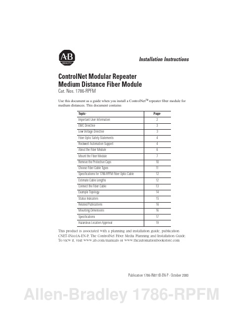
Publication 1786-IN011B-EN-P - October 2000Installation InstructionsControlNet Modular Repeater Medium Distance Fiber ModuleCat. Nos. 1786-RPFMUse this document as a guide when you install a ControlNet ™ repeater fiber module for medium distances. This document contains :This product is associated with a planning and installation guide, publication CNET-IN001A-EN-P , The ControlNet Fiber Media Planning and Installation Guide.To view it, visit /manuals or Topic:Page:Important User Information 2EMC Directive 3Low Voltage Directive 3Fiber Optic Safety Statements 4Rockwell Automation Support 4About the Fiber Module 6Mount the Fiber Module 7Remove the Protective Caps 10Choose Fiber Cable Types11Specifications for 1786-RPFM Fiber Optic Cable 12Estimate Cable Lengths 12Connect the Fiber Cable 13Example Topology 14Status Indicators 15Related Publications 16Mounting Dimensions 16Specifications17Hazardous Location Approval19Allen-Bradley 1786-RPFM6 ControlNet Modular Repeater Medium Distance Fiber ModuleAbout the Fiber ModuleUse this module when a medium-distance (distances of 3000m/ 9843ft) fiber link is required between two ControlNet products. This fiber link provides ground isolation between nodes and is less susceptible to noisy environments than traditional copper media.The distance that can be supported is dependent on the qualityof the fiber, number of splices, and connectors. The total loss ofthe fiber link must be less than 13.3 dB.The module provides:•two fiber channels•activity LED indicators for each fiber channelFigure 1 Components of the ModuleThe left side of the modules (not shown here) also contains a backplane connector42595 Publication 1786-IN011B-EN-P - October 2000ControlNet Modular Repeater Medium Distance Fiber Module 11Publication 1786-IN011B-EN-P - October 2000Choose Fiber Cable TypesMulti-fiber cables for backbone use are available with a wide range of fiber counts; between 2 and 216 fibers. Rockwell offers the short distance (< 300 m) fiber cable preterminated “zipcord” as a kit for use with the 1786-RPFS fiber module. You terminate the medium and long distance (> 300 m) cable in the field.The type of fiber cable you choose to use depends on the network environment. Consult your installation professional to determine the best type of cable to use for your environmental conditions. Refer to Publication CNET-IN001A-EN-P , The ControlNet Fiber Media Planning and Installation Guide, for details.The following figure shows an example of amulti-fiber backbone cable and two fiber interconnect cable.Figure 3 Cable TypesWhat is termination?Termination is simply the process of attaching a connector to the ends of our fiber cable. This is done in a similar manner as the coax BNC is terminated to the end of a coax cable. We terminate the coax network at the two ends of the network to prevent reflections in the system. This is not required for fiber. We recommend that you cover unused ports with a suitable protector cap to prevent dust and other contaminants from damaging the fiber transceiver ports. The protector cap for fiber is equivalent to the dust cap for a ControlNet Tap drop cable.However, for a ControlNet drop cable we also provide a 1786-TCAP for unused taps to make them electronically transparent to the network. For the Fiber repeaters we recommend that a simplex jumper be placed between the transmit port and receive port of an unused channel. This is somewhat similar to the 1786-TCAP for the coax. See Figure 2 on page 10.Allen-Bradley 1786-RPFM12 ControlNet Modular Repeater Medium Distance Fiber ModuleSpecifications for 1786-RPFM Fiber Optic CableThe quality of the fiber cable determines the distance you can achieve. Consult your local distributor for attenuation specifications prior to purchasing your fiber media components. The table below provides specifications for fiber optic cable: Item DescriptionFiber Type62.5/125µmFiber Termination Type ST®(Plastic or ceramic)Fiber Operating Wavelength1300nmOptical Power Budget13.3db11This includes all loss associated with the fiber link, including: splices, fiber attenuation, bulkhead connectors, and the 1786–RPFM ST terminations.The medium-distance fiber module (1786-RPFM) is designed for use with 62.5/ 125µm multi-mode optic fiber and plastic or ceramic ST type connectors. The wavelength used is 1300 nm.Estimate Cable LengthsThe maximum length of a fiber cable section for the 1786-RPFM is dependent on the quality of the fiber, number of splices, and the number of connectors. The total attenuation for a cable section must be less than 13.3dB.Typically cable attenuation for a wavelength of 1300nm is less than 1.5dB/km.Avoid splicing your cable. Connectors can cause considerableattenuation and limit the maximum length of your system. Becertain to check the attenuation of different cable sectionsafter the cable is installed.Publication 1786-IN011B-EN-P - October 200014 ControlNet Modular Repeater Medium Distance Fiber ModuleExample TopologyFigure 5 This topology is for example purposes only.Create a new segment with a fiber repeater.coax segment coax segmentWhen you insert a fiber repeater into your media system, you create a new segmentor link. The same restrictions on the number of taps and cable length apply to thisnew segment.Figure 6 Basic fiber topologyPublication 1786-IN011B-EN-P - October 2000Allen-Bradley 1786-RPFM16 ControlNet Modular Repeater Medium Distance Fiber ModulePublication 1786-IN011B-EN-P - October 2000Related PublicationsThe table below lists publications that you may want to refer to for additional information:Mounting DimensionsFigure 8 Mounting DimensionsPublicationPublication Number Industrial Automation Wiring and Grounding Guidelines1770-4.1ControlNet Fiber Media Planning and Installation ManualCNET-IN001A-EN-P ControlNet Coax Tap Installation Instructions 1786-5.7ControlNet COAX Media Planning and Installation ManualCNET-IN002A-EN-P ControlNet Cable System Component ListAG-2.2ControlNet Modular Repeater Medium Distance Fiber Module 17Publication 1786-IN011B-EN-P - October 2000SpecificationsSpecification Range Communication Rate 5M bits/sOperation VoltageClass 2 operational power is provided from 1786-RPA at 5 V dc (2)Backplane Power Requirements 400 mA maximum IndicatorsChannel 1 Status - Green Channel 2 Status - GreenEnvironmental ConditionsThis product must be mounted within a suitable system enclosure to prevent personal injury resulting from accessibility to live parts. The interior of this enclosure must be accessible only by the use of a tool.OperatingTemperature 0 to 60o C (32 to 125o F)Storage Temperature -40 to 85o C (-40 to 185o F)PollutionThis industrial control equipment is intended to operate in a Pollution Degree 2 environment, in overvoltage category IIapplications, (as defined in IEC publication 664A) at altitudes up to 2000 meters without derating.Relative Humidity 5 to 95% non-condensingShockOperating Non-operating30 g peak acceleration, 11(± 1)ms pulse width50 g peak acceleration, 11(± 1)ms pulse width VibrationTested 5 g @ 10-500Hz per IEC 68-2-6Allen-Bradley 1786-RPFM18 ControlNet Modular Repeater Medium Distance Fiber ModulePublication 1786-IN011B-EN-P - October 2000Fiber Type 62.5/125 micron Fiber TerminationTypeST ®(plastic or ceramic)Fiber Operating Wavelength 1300 nm Optical Power Budget 13.3 dB (1)LED Light Output 2<5 mW/mm1This includes all loss associated with the fiber link, including: splices, fiber attenuation, bulkhead connectors, and the ST terminations.2Power to operate this equipment must be supplied from a source compliant with "Class 2" as defined in the National Electrical Code ANSI/NFPA 70, or the Canadian Electrical Code - Part 1, C22.1.(1)SpecificationRangeN223。
杭州集益 GE Fanuc自动化 可编程控制产品 说明书
网络地址设定, 2-3 网络控制模块参见 NCM 网络接口单元. 参见 NIU NIU
配置, 3-3 控制数据, 3-11 描述, 3-1 DeviceNet 兼容性声明, A-1 ESD 文件, 3-5 ESD 文件, C-1 输入输出, 3-1 工作模式, 3-6 规格, 3-2 状态数据, 3-8
下表中是 GE Fanuc Automation North America, Inc 的注册商标.
Alarm Master CIMPLICITY CIMPLICITY 90–ADS CIMSTAR Field Control GEnet
Genius Helpmate Logicmaster Modelmaster Motion Mate PowerMotion
Appendix A NIU DeviceNet 兼容性声明............................................................ A-1
Appendix B NCM DeviceNet 兼容性声明...........................................................B-1
PowerTRAC ProLoop PROMACRO Series Five Series 90 Series One
Series Six Series Three VersaMax VersaPro VuMaster Workmaster
©Copyright 1999 GE Fanuc Automation North America, Inc.
常见模块及其使用与诊断
1.1734模块(1734-AND,1734-E24DC,1734-IB8,1734-OB8) 2.1756-DNB DeviceNet接口模块 3.1791IDS-IB8XOB8 8入8出安全模块 4.1791DS-IB12 12点输入安全模块 5.1732D-IB16M12MINI IP67模块 6.1732D-16CFGM12MN IP67模块 7.FDN-DN1 数据链路模块
一个或者多个子模块处于网络连接超时状态。 模块检测到一个严重的错误,使其本身丧失通讯 能力。
4
MOD/NET状态指示灯 此红色/绿色LED指示灯表明网络是否正常运行
状态
原因
描述
灭
没有电源/ 机架背板没有电源或者模块未完全插入机架背板
没有在线 中或者模块未完成Dup-MAC-ID测试或者设备没有
在线。
No Messages For Scanner
无直接的网络通讯
无任何措施,扫描器正与其 它网络通讯
77
Slave Data Size Mismatch
数据长度不符合扫描列表值
重新配置模块的通讯字长
78
No Such Device
在扫描列表中的附属设备不存在
在网络中加入此设备或在列 表中删除此项数据
79 Transmit Failure 扫描器传递信息失败
检查电缆,确认设备是否连 在网络上
80
In Idle Mode 扫描器在IDLE无效状态
把PLC5设为RUN状态,将命18令 寄存器的RUN位设为有效
81
Scanner Faulted 扫描器在错误状态
82 Fragmentation Error 检测到I/O信息块出错
Eaton C441系列通信模块产品说明说明书
Monitoring and control made simple C441 series communication modulesEaton’s motor control products offer the widestrange of communication protocol support foreasy integration into any PLC or DCS system.Both starters and soft starters use the sameC441 family of modules for communications.The modules come standard with four inputs andtwo relay outputs. C441 communication modulescan also be used independently for standaloneI/O applications.Determining your communication needsThere are many reasons to choose a particular industrial communication network. Most important is what your controller supports; after that, speed, data size, configuration, plant standards and other parameters all come into play.Need help determining which network to choose? Refer to the table below.Network configuration guideAB Maximum cable length C 500 m 1200 m 1200 m Unlimited D Unlimited D Supported controllers ssltlNode count / network 643232Infinite Infinite Determinism s t s s l Tools support s l t t l Maturity s s s l l Futurelllsss = Good, l = Neutral, t = LowA Data rates and distances for Modbus RTU and PROFIBUS are based on single segments, without using repeaters.B Maximum speeds shown are cable-length dependent. Example: PROFIBUS is 12 Mbit/s at a cable length of 100 m. At 1200 m cable length, PROFIBUS is capable of only 9600 kbit/s.C Maximum cable lengths shown are speed dependent. Example: DeviceNet can run 500 m at 125 kbit/s. If the speed is 500 kbit/s, the cable length is limited to 100 m.D The maximum cable distance between any two nodes on Ethernet is 100 m; however, the number of nodes is unlimited.C441 communication card offeringProtocolCatalog numberInput signal typeDesigned for use with …General purpose I/O 1Mounting optionsC441S611C440S811+nn 2nnStandalone—DIN/panelA C441 standalone communication modules can be used as general purpose I/O. This allows a customer to monitor the status of any non-communicating productover the selected protocol by wiring fault or auxiliary contacts from that product to the C441 communication module on-board I/O.B A C440-XCOM expansion module is required to connect any C441 communication module to a C440 Electronic Overload Relay. Note—Prior to the launch ofstandalone modules, communicating C440 assemblies used a C440-XCOM as well as an L-adapter part C440-COM-ADP , which was wired to the direct mount C441 module. When using the new standalone modules with C440, the C440-COM-ADP is no longer required.PROFIBUS (C441Q/S/QS/SS)• Capable of baud rates up to 12 Mb• PROFIBUS address set via convenient DIP switches on the device • LEDs display PROFIBUS status•Configuration using common PROFIBUS toolsDeviceNet (C441K/L/KS/LS)• Communication to DeviceNet uses only one DeviceNet MAC ID• MAC ID and baud rate set via DIP switches on the device with an option to set from the network• Configuration using common DeviceNet tools•Contain backwards compatible I/O assemblies. See C441 DeviceNet notes belowC441 DeviceNetBackwards compatibility with legacy motor control platformsC441K/L/KS/LS DeviceNet communication modules contain I/O assemblies with the same size and layout as Advantage (WPONIDNA) and IT . starter (DNSAP) platforms. These assemblies provide seamless migration paths from legacy motor control platforms to the new C440/C441 solutions. No program changes are required, meaning users can retro-fit or upgrade starter technology quickly and seamlessly. Refer to C441K/L/KS/LS User Manual MN122001EN fordetailed instructions on replacing an Advantage or IT . starter on DeviceNet.Modbus (C441M/N/P/NS/PS)• Capable of baud rates up to 115 k• Modbus address and baud rate set via convenient DIP switches on the device • LEDs display Modbus traffic•Configuration using common Modbus toolsEtherNet/IP and Modbus TCP(C441R/T/U/V)• Supports Modbus TCP or EtherNet/IP in a single device• Contains an embedded two-port switch, allowing linear or ring network configurations• Embedded Web services enable simple configuration and monitoring through Internet Explorer•IP address set via convenient DIP switches on the deviceFeatures• Common C441 communication modules cover both traditional starter and solid-state reduced voltage starter applications• C441 family modules provide support for multiple communication protocols• Modbus® RTU• Modbus TCP• DeviceNet™• PROFIBUS®• EtherNet/IP• C441 communication modules come standard with four inputs and two outputs• 120 Vac and 24 Vdc input options• Each I/O moduleis optically isolated between the field I/O and the network adapter to protect the I/O and communication circuits from possible damage due to transients and ground loops• Outputs support a user-definable safe state for loss of communication; hold last state, ON or OFF Benefits• Provide communication,monitoring and controlof motor starters andsoft starters• Input modules featurea user-definable inputdebounce that limits theeffect of transients andelectrical noise• C441 DeviceNetmodules containbackwards compatibleI/O assemblies to legacyAdvantage and IT. motorcontrol platforms forseamless migration tonewer starter technology• C441 Ethernet modulesoffer embedded Webservices for easyconfiguration andmonitoring directlythrough Internet Explorer®• Available for use asgeneral purpose I/O,giving users the abilityto monitor status of non-communicating productsover their preferrednetwork• Unique lockingmechanism providesfor easy removal of theterminal block with thefield wiring installedThe motor control center (MCC) is readyto be connected to your industrial networkwhen it arrives.Below is an image of the Eaton FlashGard® arc flashpreventative MCC prewired for DeviceNet. Dependingon the industrial network chosen, the prewired MCCwill have a trunk drop–type configuration (DeviceNet), adaisy-chain configuration (PROFIBUS and Modbus) or anEthernet configuration (Modbus TCP and EtherNet/IP).With any of these options, connecting your MCC is aseasy as plugging in a lamp.C441 series communication modulesAt Eaton, we’re energized by the challenge of powering a world that demands more. With over 100 years experience in electrical power management, we have the expertise to see beyond today. From ground-breaking products to turnkey design and engineering services, critical industries around the globe count on Eaton.We power businesses withreliable, efficient and safeelectrical power managementsolutions. Combined with ourpersonal service, support andbold thinking, we are answeringtomorrow’s needs today.Follow the charge with Eaton.Visit /electrical.Follow us on social media to get thelatest product and support information. Eaton is a registered trademark.All other trademarks are propertyof their respective owners.Eaton1000 Eaton BoulevardCleveland, OH 44122United States© 2015 EatonAll Rights ReservedPrinted in USAPublication No. BR042002EN / Z16960 September 2015。
OptiX155&622H(Metro1000)STM-4光接口板OI4功能与原理
OptiX155&622H(Metro1000)STM-4光接口板OI4介绍OI4板是STM-4光接口板(STM-4 Optical Interfaces Unit ),可以插在OptiX155/622H 设备的IU1、IU2或IU3槽位中任意一个槽位。
但只有插在IU1和IU2时才可以支持复用段保护。
OI4板实现1路STM-4光信号的接收和发送,主要完成STM-4信号的光电转换、开销字节的提取和插入处理以及线路上各告警信号的产生。
OI4板支持线路的内、外环回测试,可以方便快速地定位故障。
一.功能和原理功能OI4板提供如下功能。
● 1路光接口,可以配置I-4、S-4.1、L-4.1或L-4.2光模块。
● 具有激光器自动关断功能(ALS :Automatic Laser Shutdown )。
● 可以提取和插入开销字节。
● 能够检测并上报线路上的各种告警信号和性能事件。
● 具有内、外环回的功能。
● 支持线性复用段保护、单向复用段保护、双纤双向复用段保护以及子网连接保护。
●OI4板需要配置的参数包括:J1、C2,J1字节配置的内容为各网元收发的通道追踪识别符,对于华为的OptiX 系列设备而言,其缺省内容为:HuaWei SBS 。
C2字节配置内容为信号结构的定义,对于OptiX 系列设备的E1信号而言,其缺省内容为:TUG 结构。
原理OI4板原理如0所示。
0 OI4板的原O /E 转换E /O 转换扰码/解扰码开销提取开销插入指针调整B2、B3计算性能计数并/串变换串/并变换复用/解复用B1计算/插入公务单元时钟单元主控单元逻辑控制模块S T M -4光信号S T M -4光信号光电接口模块串并转换/开销处理模块交叉单元拉手条母板4×V C -44×V C -4控制信号从0可见,OI4板可以分为四个功能模块,分别介绍如下。
●光电接口模块:O/E 模块将接收到的STM-4光信号转化为STM-4电信号,送给串/并变换模块;E/O 模块将串/并变换模块发送的STM-4电信号转化为STM-4光信号,送上光纤。