
Parker负载敏感阀培训L90LS
Arial lift Forest machine
Excavator
Backhoe loader
Hook loader Refuse collector Large wheel loader
n When partial pump flow is used for individual functions
n At high intensity usage
n To create simple system solutions when a number of functions with different flow rates is demanded n When system layout is spread out
n At simultanious operation of functions n Power control and energy conservation
n
Reduce energy losses at idling and transportation
Suitable when;
System with variable pump and LS
Save energy, design advises
n Avoid to mix light and heavy loads from the same pump.
n Avoid to mix large and small flow demands from the same fixed pump.
n Never control max flow with line mounted restrictors.
n Always use the pump regulator to set maximum work pressure when you are using a variable pump. The pressure limiter of the valve needs to be set at least 30 bars above.
n Avoid to limit valve work port pressure with the chock valves, use the build in individual work port feed reducer.
n Make sure that the cylinders are correctly connected to the
valve, the valve is normally adapted to the cylinder ratio.
L90LS
Features
-Emergency stop
-Individual pressure compensators
-Feed reducers
-Force control
-Fast acting leake tight port relief valves -Counter pressure valve
-Built-in pilot pressure supply
-Wide range of spool-actuators
-Wide range of function adapted spools -Copied load signal
-Fixed or variable pump
L90LS
Applications
-Forest machines
-Articulated truck
cranes
-Fork lifts
-Excavators
-Refuse vehicles
-Skip loaders
-Drill rigs Customers
-SISU Logging
- F Weyhausen
-Schaeff
-Atlas Copco
-Pel Job
K170LS/K220LS
Features
Individual pressure
-Individual pressure
compensators
-Feed reducers
-Force control
-Fast acting leak tight port relief valves
-Counter pressure valve
-Built-in pilot pressure supply
-Wide range of function adapted spools
-Copied load signal
-Intermediate sections
-Mid-inlet
K170LS/K220LS
Applications
-Forest machines
-Excavators
-Backhoe loaders
-Reach stackers
-Wheel loaders
-Fork lifts
Customers
-Timberjack
-Volvo
-Barko
-Ponsse
-Kalmar LMV
HV08
Features
-Optional unloading valve in the
inlet section
-Flow force pressure
compensation
-Feed reducers
-Force control
-Fast acting leak tight port relief valves
-Counter pressure valve
-Wide range of function adapted spools
-Copied load signal
-Anti-priority function
HV08
Applications
-Reach stackers -Articulated dump
trucks
-Mobile cranes -Forest machines
Customers
-Volvo -Kalmar Kalmar LMV LMV -SMV -Lansing
Features
-Poppet Poppet design
design -zero leakage -not sensitive to temperature shocks -Fast acting leak-tight port relief valves
-Counter pressure valve -Function adapted spools -
Low pressure drops -high function speed
-low energy consumption -Priority function -Easy to install
-
Dual cylinder ports
Applications
-Wheel loaders -Reach stackers -Mobile cranes -Forest machines -Excavators
Customers
-Volvo
-Ljungby Ljungby Machine Machine -Luna
Inlet Inlet Compensator, Emergency Stop Compensator, Emergency Stop Compensator, Emergency Stop Function Function Function and Main Relief Valve and Main Relief Valve With With With Pilot Pilot Pilot Assembly
Assembly LS PX PL
P1T1
L90LS Inlet section
LS2LS2 Inlet Section Showing Direct Acting Fixed
Inlet Section Showing Direct Acting Fixed Setting Relief Valve Setting Relief Valve Cartridge
Cartridge L90LS
Inlet Section Showing Copy Spool Function
LS PX
PL
L90LS
T3T2/MP
TP
PS
LSP
Outlet Section Showing Outlet Section Showing Pressure Pressure Pressure Reducing Reducing Reducing For Pilot For Pilot For Pilot Supply
Supply and Counterpressure Valve
L90LS Outlet Section。
Parker Hannifin 加力系统控制阀门指南说明书
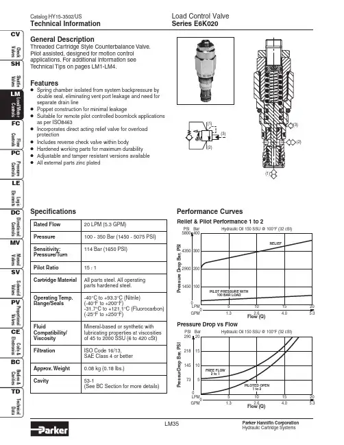
Catalog HY15-3502/USLM35Load Control Valve Series E6K020Parker Hannifin CorporationHydraulic Cartridge SystemsGeneral DescriptionThreaded Cartridge Style Counterbalance Valve.Pilot assisted, designed for motion control applications. For additional information see Technical Tips on pages LM1-LM4.Features•Spring chamber isolated from system backpressure by double seal, eliminating vent port leakage and need for separate drain line•Poppet construction for minimal leakage•Suitable for remote pilot controlled boomlock applications as per ISO8463•Incorporates direct acting relief valve for overload protection•Includes reverse check valve within body•Hardened working parts for maximum durability •Adjustable and tamper resistant versions available •All external parts zinc platedSpecificationsTechnical InformationPerformance CurvesRated Flow 20 LPM (5.3 GPM)Pressure 100 - 350 Bar (1450 - 5075 PSI)Sensitivity:114 Bar (1650 PSI)Pressure/Turn Pilot Ratio 15 : 1Cartridge Material All parts steel. All operating parts hardened steel.Operating Temp.-40°C to +93.3°C (Nitrile)Range/Seals(-40°F to +200°F)-31.7°C to +121.1°C (Fluorocarbon)(-25°F to +250°F)FluidMineral-based or synthetic with Compatibility/lubricating properties at viscosities Viscosity of 45 to 2000 SSU (6 to 420 cSt)Filtration ISO Code 16/13,SAE Class 4 or better Approx. Weight 0.08 kg (0.18 lbs.)Cavity53-1(See BC Section for more details)Flow (Q)102.651.3GPM154.0205.3Hydraulic Oil 150 SSU @ 100°F (32 cSt)P r e s su r e D r o p B a r ,P S IRelief & Pilot Performance 1 to 2Flow (Q)102.651.3GPM154.0205.3Pressure Drop vs FlowHydraulic Oil 150 SSU @ 100°F (32 cSt)73290PSI 145218P r e s s u r D r o p B a r ,P S I(1)(2)Load Control Valve Series E6K020Catalog HY15-3502/USLM36Parker Hannifin CorporationHydraulic Cartridge SystemsTechnical Information DimensionsMillimeters (Inches)Ordering InformationAdjustment StyleCrackingPressureSealsCode Seals / Kit No.N Nitrile, Buna-N (Std.) /(SK30087N-1)VFluorocarbon /(SK30087V-1)Code Pilot Ratio K 15 : 1E6Pilot RatioLoad Control Valve*Standard valve is set to crack at 215 Bar (3120 PSI). Valve to be set to 1.3 times maximum load induced pressure.Code Body Material A Aluminum SSteelCode Porting3103/8″ BSP (main) 1/4″ BSP (aux)3183/8″ SAE (main) 1/4″ SAE (aux)3123/8″ BSP Dual Cavity 3193/8″ SAE Dual Cavity Code Adjustment Style / Kit No.Z Screw Adjust (Standard)TTamper Resistant (TC1125)020Code Cracking PressureOmit for no setting (Standard)*Specify setting if requiredBody MaterialPortingLine BodyLB10Order Bodies SeparatelyK。
Parker 多路阀-工程机械
F1与F2的做功相等
V = A1S1 = A2S2 W1 = F1S1 = pA1S1 W2 = F2S2 = pA2S2 W1 = W 2
9
液压传动 基础知识
c:流体的能量守恒 - 柏努利 (Bernoulli) 方程
10
液压技术的基础理论
3.几个概念
a) 压力 - 单位面积上所受的作用力
定量泵或变量泵 复制负载信号 紧急停止 流量共享 单独的压力补偿器 供给减压阀 力控制(力反馈功能) 响应快, 无泄漏油口溢流阀 阀芯执行器范围广 阀芯功能广 背压阀 内置式先导压力控制油源 可选装多功能阀块
44
选项功能举例
进口片中的旁通功能, 用于定量泵供油的系统 泵卸载功能起作用时切断泵进口, 这样使系统包括了急停功能 特定片的压力补偿 特定片的负载保持单向阀 特定片的溢流和防气穴功能 特定片的供给减压 特定油口的力反馈功能, 能实现力传感也提供液压斜坡功能 负载信号复制功能消除微下沉 在出口片中的内置先导压力功能 背压功能,提供非常好的补油特性和卸载下落的可能性 特定的双速功能, 能够实现像起重机和高空作业车这类机器的性能与精度之间的 切换 自动停止功能,用于选定的机器运动发生过载或者碰上其他的预先设定的限位 手柄脱离功能, 当远程控制起作用时, 它使直动式操作杆不起作用 机器的优先功能, 如制动和转向
5
液压传动的优缺点
缺点
噪声; 外部泄漏,会造成环境污染,即使是少量的矿物油漏泄, 也会毁坏大片的地表水;不过现在已越来越普遍地使用可 生物降解的液压油液; 易受污染,液压工作介质中的污染物质会导致介质变质、 元件磨损、系统性能恶化; 对环境温度较敏感,温度过高或过低均会影响甚至破坏元 件的可靠性和系统的性能。 液压油液中的气体会破坏系统的刚性,引起气穴,导致液 压泵和其它液压元件的损坏。
Parker软管培训资料课件

26
学习交流PPT
27
学习交流PPT
28
学习交流PPT
29
学习交流PPT
30
软管接头- 是确保软管总成可靠工作的关键
软管总成的主要失效模式: • 软管爆破于管体 • 软管爆破于接头端部 • 软管接头拔脱 • 软管针状穿孔泄漏 • 软管接头内连接处泄漏 • 软管接头外连接处泄漏
学习交流PPT
软管的抗高原紫外线性能
橡胶软管: • 最优-301,421,431,77C,78C • 优 -451ST,471ST • 较优 -381,481,451TC,771,772,781,
782,792 热塑软管具有更优越的抗紫外线性能
学习交流PPT
23
学习交流PPT
24
学习交流PPT
25
学习交流PPT
学习交流PPT
7
软管的基本参数
基本参数:
• 内径,外径
• 额定工作压力,最低 爆破压力,压力脉冲 寿命
• 耐真空度 • 介质适应性
• 适应温度范围 • 最小弯曲半径
• 长度变化率 • 耐磨性 • 耐臭氧 • 高压绝缘型 • 容积膨胀率 • 低温柔软性 • 粘合强度
学习交流PPT
8
软管选择的基本条件
短
学习交流PPT
32
软管总成的正确安装
学习交流PPT
33
学习交流PPT
34
学习交流PPT
35
POLYFLEX 产品)
学习交流PPT
6
热塑软管的优点
• 介质适应性强,耐油性好 • 耐磨性好-是天然胶的20倍 • 弹性好,耐扯断强度高-是橡胶的3倍 • 温度适应范围广- -70到+120C • 重量轻 • 弯曲半径小- 是一般胶管的1/2 • 阻燃性好 • 抗老化性能强,耐压力脉冲寿命长 • 容积膨胀系数小 • 外表光洁,美观,流体阻力小
派克汉尼汾工程机械用方向控制阀 L90LS 商品说明书
样本信息未使用本文所述之产品及相关项目选择不当或使用不当可能会造成人员死亡、警告样本布局除一般信息和基本技术数据外,该样本还对L90LS 可配置的选配功能做了描述。
我们可据此对L90LS 进行定制配置,以便以更佳的方式控制您的机器。
除一般信息和基本技术数据外,该样本还对阀门功能片中可配置的选配功能做了描述。
阀门的每个功能区域都有一个副标题,标题后面附有简短的描述。
如果某个功能区有多个不同的位置,则会在副标题的方括号内标注项目编号,例如[P16]溢流阀。
再接下来是一系列带有代号的选项,例如PA1、PS 、Y 以及每个代号的简短描述。
或者是一个或多个压力、流量或电压选项。
第8页的一般液压原理图中展示了L90LS 阀的基本功能区、以及代表这些功能区的条目编号。
有关L90LS 所有选项的信息,请参见样本MSG17-8504。
文档和订购L90LS 可在派克的在线产品配置器中根据客户的需求定制,定制规格通常在派克销售公司与客户协商后确定。
每个阀门配置都有唯一的ID 号、详细的代号报告、3D 模型、2D 图纸、备件清单、液压原理图、材料清单和装配说明。
除了前面提到的文档外,还登录XXXXX 观看每个选件的装配说明视频。
阀部件订购可使用物料清单通过派克销售公司进行。
尽早咨询,以节约时间和成本我们的工程师经验丰富,他们对不同类型的液压系统及其工作原理都有深入的了解。
他们可以帮助您选择符合要求的阀门。
我们建议在项目规划阶段尽早咨询派克。
派克保留修改产品的权利,恕不另行通知。
本样本中使用了典型的曲线和图表。
即使样本不断修订和更新,也不可避免存在出错的可能。
请联系派克汉尼汾,了解更多有关产品的详细信息。
概述 (4)技术数据 (5)压力 (5)内部先导压力 (5)通流流量 (5)重量 (5)过滤 (5)液压油 (5)温度 (5)[P03] 泵调节器设置 (6)油口 (6)[P04] 接口螺纹 (6)进口片 (6)工作片 (6)出口片 (6)液压原理图 (7)进口片 (8)[P15-P29] 进口片 (8)[P15] 进口片 (8)用于[P15] CFC、LS1进口片 (9)[P16] 溢流阀 (9)[P17] 压力设定 (9)用于[P15] LS2进口片 (9)[P16] 泄压阀 (9)[P17] 压力设定 (9)[P20] 负载信号系统 (10)[P25] 回油口T1 (10)[P26] 进油口P1 (10)出口片 (11)[P30 - P44] 出口片 (11)[P30] 出口片 (11)用于出口片[P30] US (12)[P31] LS油口 (12)[P32] 进油口P2 (12)[P33] 背压阀/回油口T2 (12)[P34] 回油口T3 (12)[P37] 内部先导压力供油 (12)[P39] 先导过滤器 (12)[P40] 回油口,用于先导回路..............................................12工作片.. (13)[P45-P89] 工作片 (13)[P47] 工作片的基本变型 (13)[P50] 阀芯执行器 (14)比例远程控制阀芯执行器,带封闭阀芯端 (14)比例远程控制阀芯执行器,带封闭阀芯端 (15)比例远程控制阀芯执行器,带封闭阀芯端 (16)手动控制阀芯执行器,带封闭阀芯端 (17)[P51] 手柄支架 (17)[P55A,B] 先导节流器 (18)[P56] 插头类型 (18)[P60] 阀芯功能 (19)[P64A, B] 力反馈 (20)[P66]压力补偿器/负载保持单向阀 (20)[P69] 阀芯名称 (21)[P71A,B] 工作油口公称流量 (21)[P72] 流量设定 (21)[P72A] 所需的设定流量 (21)[P72B] 所需的设定流量 (21)[P75] 进给减压阀 (21)[P75A] A油口的进给减压设定 (21)[P75B] B油口的进给减压设定 (21)[P76A,B] 油口溢流阀和/或防气穴阀 (22)信息 (23)[P50] EC2手动越权 (23)尺寸图 (24)备件 (25)L90LS具有四个工作段。
Parker Pneumatic N Series neumatic阀门说明书
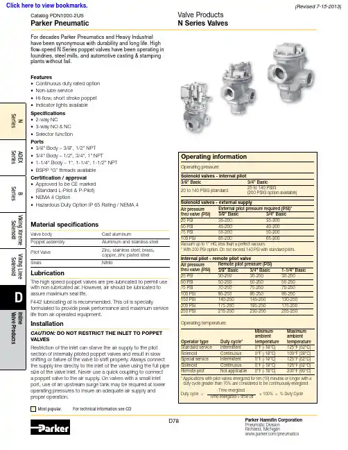
Material specificationsValve body Cast aluminumPoppet assembly Aluminum and stainless steel Pilot Valve Zinc, stainless steel, brass,copper, zinc plated steel SealsNitrileFeatures• Continuous duty rated option • Non-lube service• Hi-flow, short stroke poppet • Indicator lights available Specifications • 2-way NC• 3-way NO & NC • Selector functionPorts• 3/8" Body – 3/8", 1/2" NPT • 3/4" Body – 1/2", 3/4", 1" NPT• 1-1/4" Body – 1", 1-1/4", 1-1/2" NPT • BSPP “G” threads availableCertification / approval• Approved to be CE marked (Standard L-Pilot & P-Pilot)• NEMA 4 Option• Hazardous Duty Option IP 65 Rating / NEMA 4LubricationThe high speed poppet valves are pre-lubricated to permit use with non-lubricated air. However, air should be lubricated to assure maximum seal life.F442 lubricating oil is recommended. This oil is speciallyformulated to provide peak performance and maximum service life from air-operated equipment.InstallationCAUTION: DO NOT RESTRICT THE INLET TO POPPET VALVESRestriction of the inlet can starve the air supply to the pilot section of internally piloted poppet valves and result in slow shifting or failure of the valve to shift properly. Always connect the supply line directly to the inlet of the valve using the full pipe size of the valve inlet. Never use a quick coupling to connect a poppet valve to the air supply. On valves with a small inlet port, use of an upstream surge tank may be required at lower operating pressures to insure an adequate air supply and proper operation.Parker PneumaticN Series ValvesSingle Solenoid, Locking manual override, internal “P” pilot 140 PSI, standard service, junction box w/ light.Body In / cyl Exhaust 2-way, 2-position 3-way, 2-position 3-way, 2-positionSingle Remote Pilot, 1/4" NPT remote pilot port with internal pilot return.BodyIn / cyl Exhaust 2-way, 2-position3-way, 2-position 3-way, 2-positionSingle Solenoid, Locking manual override, internal “P” pilot 125 PSI, standard service, P-pilot junction box w/ light.Body In / cyl Exhaust2-way, 2-position 3-way, 2-position 3-way, 2-positionSingle Remote Pilot, 1/4" NPT remote pilot port with internal pilot return.Body In / cyl Exhaust 2-way, 2-position 3-way, 2-position 3-way, 2-positionParker PneumaticN Series Valves Model Number Index“N” Series 3/8", 3/4" & 1-1/4" Body Sizes - Solenoid ‘L’ PilotNote: BSPP is to the ISO 228 standard, and requires an R-BSPT male fitting.“N” Series 1-1/4" Body Sizes - Solenoid Hi-Flow ‘P’ PilotR-BSPT male fitting.Parker PneumaticReplacement PilotsDescriptionHazardous duty L-pilot NEMA 4 L-pilot Hazardous duty L-pilot - UL & CSA K0451025**N/AOverride typeLocking Non-Locking Locking Non-Locking Hazardous duty with override K0453025**K0452025**NEMA 4 with overrideK2553025**K255202549** Voltage code - 49 & 53N Series Valve Replacement PartsReplacement PilotsDescription Standard L-pilot Continuous duty L-pilot Override type Locking Non-locking Locking Non-locking Basic with overrideK0653035**K0652035**K0853025**K0852025**JIC with junction box & override K0656035**K0655035**K0856025**K0855025**JIC pilot with junction box &override & indicator lights (120VAC only)K0659035**K0658035**K0859025**K0858025**** Voltage code - (reference model index for availability)Replacement PilotsDescription Heavy duty P-Pilot Override type No override Non-locking Locking Basic with overrideK1351045**N/A N/A JIC with junction box & override N/A K1355045**K1356045**JIC Pilot with junction box & override & indicator lights (120VAC only)N/AK135804553K135904553** Voltage code - 49 & 53Voltage Code **Voltage Coil 60Hz 50Hz DC 19" Leads 72" Leads 4224——K593099—43—24—K593098—45——12K593094—49—— 24K593097—51——48—K59325453115——K593108—58—230—K593111—Coils for L-Pilot Operated ValvesCoils for P-Pilot Operated ValvesVoltage Code **Voltage Coil60Hz 50Hz DC 19" Leads 72" Leads 4012——K593007—41,4224—6K593003—45*——12K593010—49*——24 (Standard)K593014—79——24 (ArcSuppressed)K593271—51*——48—K59318553*120110—K593025—57*240240—K593035—60240220—K593035—61——120K593041—* Indicates voltages approved for solenoid operators designed for use inhazardous locations.NVoltage Code* *Internal Pilot -3/8" & 3/4" Basic BodyKey 3/8" Body3/4" Body Inch mm Inch mm A 1.5640 2.1354B 1.5038 1.9449C1.8146 1.3434D .5614.5614E 3/8-16UNC 7/16" deep 3/8-16UNC 9/16" deepF 1.7544 2.2557G 1.5038 1.5038H 5.921507.14181J3.1981 3.7595K 1.8847 2.4462N 1.4437 1.7845P 7.361968.58218Q2.31593.0984216891351051A 10AKey 3/8" Valve 3/4" Valve Description4*H14510H13676U-cup (3/8), o-ring (3/4)5K493002K493009Stem6K202001K202002Lower piston assy.7*H14509H13676U-cup (3/8), o-ring (3/4)8H17811H17813Washer (2)9H06326H06332Stop nut (2)10K103035K103053Bottom cap (N.C.)10A K092020K092034Bottom cap assy. (N.O.)11*K183049K183057Gasket 12K473014K473015Spring 13K563015K563017Adapter 14*K41RB72121K41RB72221O-ringKey3/8" Valve 3/4" Valve Description1—1/2" Tap K053075Body (N.C.)3/8" TapK0530223/4" Tap K0530761/2" Tap K0530231" Tap K0532201A—3/4" Tap K053077Body (N.O.)3/8" Tap K0530253/4" Tap K0530781/2" Tap K0530261" Tap K0532182K212001K212002Upper piston assy Top view indicates flow through 3-Way valve with coil de-energized.NOTE: For normal valve operation, override must be in “out” position.Service KitsInclude all parts normally required for in-service maintenance:3/8" Basic valve with standard service L -Pilots .................K352076 3/8" Basic valve with continuous duty L -Pilots .....................K3522763/4" Basic valve with standard service L -Pilots .................K3520773/4" Basic valve with continuous duty L -Pilots .....................K352277Exhaust PressureNormally Closed1351A 10A216891351410Key 3/8" Valve 3/4" Valve Description 4*K41RB72211H13676O-ring 5K493002K493009Stem6K202001K202002Lower piston assy.7*K41RB72210H13676O-ring 8H17811H17813Washer (2)9H06326H06332Stop nut (2)10K103035K103053Bottom cap (N.C.)10A K092020K092034Bottom cap assy. (N.O.)11K473014K473015Spring 12*K183049K183057Gasket 13K563016K563021Adapter 14*K41RB72121K41RB72221O-ringKey 3/8" Valve 3/4" Valve Description1—1/2" Tap K053067Body (N.C.)3/8" TapK0530193/4" Tap K0530691/2" Tap K0531571" Tap K0532211A—3/4" Tap K053065Body (N.O.)3/8" Tap K0530183/4" Tap K0530701/2" Tap K0530641" Tap K0532192K212001K212002Upper piston assy 3*H13648H13728SealNormally ClosedNormally OpenExternal Pilot -3/8" & 3/4" Basic BodyKey3/8" Body 3/4" Body InchmmInchmmA 1.5640 2.1354B 1.5038 1.9449C1.8146 1.3434D .5614.5614E3/8-16UNC 7/16" deep 3/8-16UNC 9/16" deepF 1.7544 2.2557G 1.5038 1.5038H 6.421637.45189J 3.1981 3.7595K 1.8847 2.4462N1.4437 1.7845P 7.862008.89226Q2.31593.0984R4.341105.38137Top view indicates flow through 3-Way valve with coil de-energized.NOTE: For normal valve operation, override must be in “out” position.Service KitsInclude all parts normally required for in-service maintenance:3/8" Basic valve with standard service L -Pilots .................K352076 3/8" Basic valve with continuous duty L -Pilots .....................K3522763/4" Basic valve with standard service L -Pilots .................K3520773/4" Basic valve with continuous duty L -Pilots .....................K352277Exhaust PressureTop view indicates flow through 3-Way valve with coil de-energized.NOTE: For normal valve operation, override must be in “out” position.Service KitsInclude all parts normally required for in-service maintenance:1-1/4" Basic valve with standard service P-Pilots ............K352078Exhaust Pressure5Key 1-1/4" Valve Description 4*H13728Seal 5K493016Stem6K313028Lower piston 7*H13728Seal 8H17817Washer 9H06338Stop nut10K092046Bottom cap (N.C.)10A K103061Bottom cap (N.O.)11*K183058Gasket 12K473016Spring 13K012003Adapter 14*K41RB72143O-ringKey1-1/4" Valve Description11" Tap K053111Body (N.C.)1-1/4" Tap K0531121-1/2" Tap K0531131A1" Tap K053114Body (N.O.)1-1/4" Tap K0531151-1/2" Tap K0531162K313029Upper piston assy 3*H13752O-ringInternal Pilot - 1-1/4" Basic BodyInternal Pilot - 1-1/4" Basic BodyKey 1-14" BodyInch mm A 3.0076B2.2557C 1.3434D 1.1930E 1/2-13 UNC 3/4 DeepF 3.1380G 1.5038H 9.30236J5.34136K 3.4487N2.3159P 11.14283Q4.56116Continuous Duty Pilot - 1-1/4" Basic BodyContinuous Duty Pilot - 1-1/4" Basic BodyKey 1-1/4" BodyInch mmA 3.0076B 2.2557C1.3434D 1.1930E 1/2-13 UNC 3/4 DeepF 3.1380G 1.5038H 9.02229J 5.34136K 3.4487N2.3159P 10.45265Q4.561165Key 1-1/4" Valve Description 4*H13728Seal 5K493016Stem6K313028Lower piston 7*H13728Seal 8H17817Washer 9H06338Stop nut10K092046Bottom cap (N.C.)10A K103061Bottom cap (N.O.)11*K183058Gasket 12K473016Spring 13K012003Adapter 14*K41RB72143O-ringKey1-1/4" Valve Description11" Tap K053111Body (N.C.)1-1/4" Tap K0531121-1/2" Tap K0531131A1" Tap K053114Body (N.O.)1-1/4" Tap K0531151-1/2" Tap K0531162K313029Upper piston assy Normally ClosedTop view indicates flow through 3-Way valve with coil de-energized.NOTE: For normal valve operation, override must be in “out” position.Service KitsInclude all parts normally required for in-service maintenance:1-1/4" Basic valve with continuous duty L -Pilot ...................K352080Exhaust PressureInternal Return - 3/8", 3/4", 1-1/4" Basic BodyKey3/8" Body 3/4" Body 1-1/4" Body Inch mm Inch mm Inch mmH 3.1981 3.7595 5.34136J 1.8848 2.4462 3.4487M 1.4437 1.7845 2.6667N 4.22107 5.311357.19183Q2.31593.09784.56116Key 3/8" Valve 3/4" Valve1-1/4" Valve Description 5K493002K493009K493016Stem6K202001K202002K313028Lower pistonassy.7*H13499H13676H13728Seal 8H17811H17813H17817Washer (2)9H06326H06332H06338Stop nut (2)10K092020K092034K092046Bottom cap(N.C.)10A K103035K103053K103061Bottom cap(N.O.)11*K183049K183057K183058Gasket 12K473014K473015K473016Spring 14*K41RB72121K41RB72221K41RB72143O-ring 21K123018K123021K123024CoverKey 3/8" Valve 3/4" Valve1-1/4" ValveDescription1—1/2" TapK0530751" Tap K053111Body (N.O.)3/8" Tap K0530223/4" Tap K0530761-1/4" Tap K0531121/2" Tap K0530231" Tap K0532201-1/2" Tap K0531131A—1/2" TapK0530771" Tap K053114Body (N.C.)3/8" Tap K0530253/4" Tap K0530781-1/4" Tap K0531151/2" Tap K0530261" Tap K0532181-1/2" Tap K0531162K212001K212002K313029Upper piston assy 3*H13648H13728H13752Seal 4*H14510H13676H13728Seal2152151A 7*10Service KitsInclude all parts normally required for in-service maintenance:3/8" Basic valve ........................K3520733/4" Basic valve .........................K3520741-1/4" Basic valve .....................K352075Normally ClosedTop view indicates flow through 3-Way valve.NOTE: For normal valve operation, override must be in “out” position.Exhaust PressureTop view indicates flow through 3-Way valve.NOTE: For normal valve operation, override must be in “out” position.Exhaust Pressure132151051A 7*Internal Return - 3/8", 3/4", 1-1/4" Basic BodyKey3/8" Body 3/4" Body 1-1/4" Body Inch mm Inch mm Inch mm A 1.5640 2.1354 3.0076B 1.5038 1.9449 2.2557C 1.1329 1.1329 2.3860D .5614.5614 1.1930E 3/8–16UNC 7/16" deep 3/8– 16UNC 9/16" deep 1/2–13UNC 3/4" deep F 1.7544 2.2557 3.1379G 1.5640 2.1354 3.1379H 3.1981 3.7595 5.34136J 1.8848 2.4462 3.4487K 2.3159 3.0978 4.56116L 4.34110 5.381377.31186M5.311356.341617.88200N Left of centerOn center.53 13 1.0025Q1.4437 1.78452.3159Key 3/8" Valve 3/4" Valve1-1/4" Valve Description 5K493002K493009K493016Stem6K202001K202002K313028Lower pistonassy.7*H13499H13676H13728Seal 8H17811H17813H17817Washer (2)9H06326H06332H06338Stop nut (2)10K092020K092034K092046Bottom capassy. (N.C.)10A K103035K103053K103061Bottom cap(N.O.)11*K183049K183057K183058Gasket 12K473014K473015K473016Spring 13K563016K563021K563027Adapter 14*K41RB72121K41RB72221K41RB72143O-ring 21K323027K323027Not used CoverKey3/8" Valve 3/4" Valve 1-1/4" Valve Description11/4" Tap K0530111/2" Tap K0530671" Tap K053143Body (N.O.)—3/4" Tap K0530691-1/4" Tap K0531101/2" TapK0531571" Tap K0532211-1/2" Tap K0531461A 1/4" Tap K0530101/2" Tap K0530651" Tap K053159Body (N.C.)—3/4" Tap K0530701-1/4" Tap K0531441/2" Tap K0530641" Tap K053 2191-1/2" Tap K0531452K212001K212002K313029Upper piston assy 3*H13648H13728H13752Seal 4*H13529H13676H13728SealNormally ClosedService KitsInclude all parts normally required for in-service maintenance:3/8" Basic valve ........................K3520313/4" Basic valve ........................K3520561-1/4" Basic valve .....................K352083Catalog PDN1000-2USParker PneumaticParker Hannifin Corporation Pneumatic Division Richland, Michigan/pneumaticsD88Valve ProductsN Series Valve DimensionsInternal Return -3/8" & 3/4" Basic BodyKey 3/8" Body 3/4" Body 1-1/4" Body Inch mm Inch mm Inch mm A 1.5640 2.1354 3.0076B 1.5038 1.9449 2.2557C 1.1329 1.1329 2.3860D .5614.5614 1.1930E 3/8–16UNC 7/16" deep 3/8–16UNC 9/16" deep 1/2–13UNC 3/4" deep F 1.7544 2.2557 3.1379G 1.5640 2.1354 3.1379H 3.1981 3.7595 5.34136J 1.8848 2.4462 3.4487K .5013.5013.5013L .113.164.256M 1.4437 1.7845 2.6667N 4.22107 5.311357.19183P 4.78121 5.561417.53191Q2.31593.09784.56116Internal Return -3/8" & 3/4" Basic Body3/8" Body 3/4" Body 1-1/4" Body Key Inch mm Inch mm Inch mm A 1.5640 2.1354 3.0076B 1.5038 1.9449 2.2557C 1.1329 1.1329 2.3860D .5614.5614 1.1930E3/8–16UNC 7/16" deep 3/8–16UNC 9/16" deep 1/2–13UNC 3/4" deep F 1.7544 2.2557 3.1379G 1.5640 2.1354 3.1379H 3.1981 3.7595 5.34136J 1.8848 2.4462 3.4487K 2.3159 3.0978 4.56116L 4.34110 5.381377.31186M 5.31135 6.341617.88200N Left of centerOn center.53 13 1.0025Q1.44371.78452.3159Internal Return - 3/8" & 3/4" Basic BodyExternal Return - 3/8" & 3/4" Basic Body1/4 NPT。
朴克(Parker)Series V26部分方向控制阀说明书

Bulletin HY14-2707-B1/USSeries V26Pressure Compensated Directional Control ValveEffective:February 1, 2004Supersedes:Cat. No. GPD-1450 dated 3/98SpecificationsDescriptionThe Parker Series V26 Sectional Directional Control Valves provide pressure compensated operation for variable displace-ment, load sensing, and fixed displacement systems.➀Contact the factory for optional portingINLET COVER•3-Way, 4-Way and 4-Way Float operation•Numerous manual spool positioner options plus remote hydraulic or electric solenoid operation •Work port relief valves available •Load sense bleed-off orifice plug•Single handle or two function mechanical joystick control of manual sections•Remote electronic and handle control of solenoid sections•Load sensing work sections with individual pressure compensation (pre-compensation)•Unloading section available for use in fixed displacement systems•Precise metering spools offering compensated flows up to 25 GPM (95 LPM)•Continuous system operating pressures to 3500 PSI (Work port pressures to 5000 PSI)•Utilizes many common components such as relief valves,spool positioners and handles with Series V20FeaturesOUTLET COVERS AND UTILITY SECTIONSWORK SECTIONSNo. 23937, V26 Pressure CompensatedWORK SECTIONSNo. 23937, V26 Pressure CompensatedWORK SECTIONSNo. 23937, V26 Pressure Compensated Spool Positioners and ActuatorsWORK SECTIONSNo. 23937, V26 Pressure CompensatedDIMENSIONS ARE IN INCHES (MILLIMETERS) AND ARE FOR REFERENCE ONLY.DIMENSIONS - Typical V20C and V20LS AssemblyDirectional Control Valve Assembly (Manually Operated)DIMENSIONSDirectional Control Valve Assembly (Solenoid Operated)DIMENSIONS ARE IN INCHES (MILLIMETERS) AND ARE FOR REFERENCE ONLY.Parker Hannifin CorporationHydraulic Valve Division 11ORDERING CODEBulletin HY14-2707-B1/US,3C, 3/04, PHD Copyright 2004, Parker Hannifin Corporation, All Rights ReservedFAILURE OR IMPROPER SELECTION OR IMPROPER USE OF THE PRODUCTS AND/OR SYSTEMS DESCRIBED HEREIN OR RELATED ITEMS CAN CAUSE DEATH, PERSONAL INJURY AND PROPERTY DAMAGE.This document and other information from Parker Hannifin Corporation, its subsidiaries and authorized distributors provide product and/or system options for further investigation by users having technical expertise. It is important that you analyze all aspects of your application and review the information concerning the product or system in the current product catalog. Due to the variety of operating conditions and applications for these products or systems, the user, through its own analysis and testing, is solely responsible for making the final selection of the products and systems and assuring that all performance, safety and warning requirements of the application are met.The products described herein, including without limitation, product features, specifications, designs, availability and pricing, are subject to change by Parker Hannifin Corporation and its subsidiaries at any time without notice.WARNINGThe items described in this document are hereby offered for sale by Parker Hannifin Corporation, its subsidiaries or its authorized distributors. This offer and its acceptance are governed by the provisions stated in the "Offer of Sale".Offer of Sale Parker Hannifin CorporationHydraulic Valve Division 520 Ternes Avenue Elyria, Ohio, USA 44035Tel:(440) 366-5200Fax:(440) /hydraulicvalve AVAILABLE OPTIONS。
派克(Parker) Moduflex IO-Link阀岛系列说明书
IO-Link端口类别 A类
IO-Link 3针 3针 3针
辅助电源 3针 3针 5针
辅助电源针脚定义 重量(g)
订货号
1&3
160 P2M2HBVL12400A13
4&3
160 P2M2HBVL12400A43
4&2
160 P2M2HBVL12400A42
๑使ᆩ用IO-IOL-iLniknᆩk用ᇀ于ݥ非ྪ网ஏ络ॐ架ࠓ构I/IO/੦O控制
Փ⫼使ᏺ用䲚带៤集I成O-ILOin- LkiЏn kキ主站ഫ模ⱘ块P的LCPˈL C⫼,Ѣ用I/于O᭄ ᇥI/Oⱘ数ᴎ更఼少的机器
* I/*OI-/LOi-nLkin㒓k 线㓚缆ⱘ的᳔最大䭓长ᑺ度202m0m * ߽* ⫼利I用O-ILOi-nLkin䖲k连接控ࠊ制᠔所᳝有ᴀ本ഄ地ⱘ的
卓越价值
本产品通过低成本通讯连接从而降低总体 机器成本,同时提供诊断信息。Moduflex IO-Link可通过PLC上传诊断信息,而且还配 有本地LED状态指示灯,帮助故障诊断。
• IO-Link通信状态 • 模块错误 • 输出错误 • 辅助电源
A类或B类端口
Moduflex阀岛 H系列微型阀岛
H系列ISO阀岛
© 2017 派克汉尼汾公司版权所有。保留所有权利。
H ISO 15407-2 Cv: 0.55 - 1.1 最多可带24个线圈 42mA/线圈
H ISO 5599-2 Cv: 1.5 - 6.0 最多可带24个线圈 133mA/线圈
23-06-A PNEU-CH-4P-IOLINK
B类
5针
2&5
140 P2M2HBVL12400B25
Parker负载敏感阀培训(L90LS)
50
100
200
50 200 56 6 BAR 210 210 106 6 BAR
100 206 6 BAR 210
200
210
THREE FUNCTION WITH INDIVIDUAL PRESSURE COMPENSATORS
Mobile Controls Division
30/03/2012
30/03/2012
Mobile Controls Division
K170LS/K220LS /K220LS
LS-systems Flow/section 170 l/min, without compensator 210 l/min Nodular iron Max pressure 320 bar Stackable 1 to 10 sections Motorports
compensators Feed reducers Force control Fast acting leak tight port relief valves Counter pressure valve Built-in pilot pressure supply Wide range of function adapted spools Copied load signal Intermediate sections Mid-inlet
50
100
200
50 200 210
100
200
210
210
210
210
210
210
THREE FUNCTIONS WITHOUT INDIVIDUAL PRESSURE COMPENSATORS
Mobile Controls Division
负载敏感控制系统、控制方法及液压系统[发明专利]
专利名称:负载敏感控制系统、控制方法及液压系统专利类型:发明专利
发明人:单增海,胡小冬,焦国旺,周彬
申请号:CN201610158287.X
申请日:20160318
公开号:CN105604996A
公开日:
20160525
专利内容由知识产权出版社提供
摘要:本发明公开了一种负载敏感控制系统、控制方法及液压系统,涉及工程机械领域,用以实现系统压力与负载压力的自适应匹配。
该负载敏感控制系统包括变量泵、负载反馈油路和压差控制阀;压差控制阀与变量泵和负载反馈油路相连,压差控制阀能使得变量泵的出口压力与负载反馈油路上的负载压力之间的差值是变化的。
上述技术方案,提供了一种压差可变的负载敏感系统,该系统能够消除发动机怠速操作中出现的流量饱和现象,改善负载敏感系统的调速特性,同时还提高了系统的节能性。
申请人:徐州重型机械有限公司
地址:221004 江苏省徐州市铜山路165号
国籍:CN
代理机构:中国国际贸易促进委员会专利商标事务所
代理人:邹丹
更多信息请下载全文后查看。
阀门培训内容
阀门培训内容一、前言阀门是流体输送系统中的控制部件,具有截止、调节、导流、稳压、分流、溢流、泄压等功能。
阀门广泛应用于石油、化工、天然气、电力、冶金、食品、制药等行业。
为了提高阀门使用效率,保障生产安全,降低维护成本,本培训旨在使参训人员全面了解阀门的结构、原理、选型、安装、调试、维护及故障处理等方面的知识。
二、阀门基础知识1. 阀门分类阀门按照结构可分为截止阀、球阀、蝶阀、闸阀、截止止回阀、安全阀等;按照驱动方式可分为手动、电动、气动、液压等;按照连接方式可分为法兰连接、螺纹连接、焊接连接等。
2. 阀门结构及工作原理阀门主要由阀体、阀盖、阀杆、阀瓣、密封圈等组成。
阀门通过改变阀门通道的截面积,实现流体的截止、调节、导流等功能。
不同类型的阀门具有不同的工作原理,如截止阀通过升降阀瓣实现截止,球阀通过旋转球体实现截止,蝶阀通过旋转蝶板实现调节等。
3. 阀门材质及密封面材料阀门的材质和密封面材料对阀门的使用性能和寿命具有重要影响。
阀门材质包括铸铁、碳钢、不锈钢、合金钢等;密封面材料包括橡胶、聚四氟乙烯、金属等。
根据流体介质的性质,选择合适的阀门材质和密封面材料。
三、阀门选型与安装1. 阀门选型(1)满足生产工艺要求;(2)保证流体介质安全、清洁、无泄漏;(3)操作简便,维护方便;(4)经济合理,降低成本。
2. 阀门安装(1)阀门安装方向应正确;(2)阀门与管道连接应牢固、严密;(3)阀门安装位置应便于操作、检修;(4)阀门安装高度应符合设计要求。
四、阀门调试与维护1. 阀门调试阀门调试主要包括手动操作、电动操作、气动操作等。
调试过程中,应检查阀门启闭是否灵活、密封是否严密、驱动装置是否正常。
对于特殊阀门,如安全阀、减压阀等,还需进行功能调试。
2. 阀门维护阀门维护主要包括日常检查、定期保养、故障排除等。
日常检查应关注阀门密封性能、驱动装置、连接部位等;定期保养应进行阀门清洗、润滑、更换密封圈等;故障排除应遵循先分析原因,后采取相应措施的原则。