
高压泵说明书
Brass Standard and Flushed
3535,3535C
3531,3531C Stainless Steel
Standard and Flushed
Nickel Aluminum Bronze Standard
3537
SPECIFICATIONS
U.S. Measure Metric Measure
800
Motor Pulley
30 114 16.5
20.6
24.7
667
Sizes
25 95
13.7
17.2
20.6
556
DETERMINING THE PUMP rpm
Rated gpm Rated rpm
=
“Desired” gpm
“Desired” rpm
DETERMINING THE REQUIRED H.P.
45936 16612 44487 27488
27790 POP 92538 S 43864 CM
27790 POP 92538 S 43864 CM
27790 92538 43864
† 45116 126587 100488
44739
SSZZ STCP R NBRS FPM
45116 126587 100488
75 88 90 95 96 97
98 99 100 101 106
107 110
112
117 126
127
128 141 155
156 157 158 159
162 163
164 166 167 168 170 171 172
173 174 185 188 250
PART NUMBER
3535
ELECTRIC HORSEPOWER REQUIREMENTS
FLOW PRESSURE
rpm
DRIVE
psi
psi
psi
800 1000 1200
Consult CAT PUMPS
U.S.
bar
bar
bar
for
gpm l/m
55Байду номын сангаас
70
85
Pump and
36 136 19.8
24.7
29.7
(48 mm) (4 l)
Maximum Liquid Temperature ....................................160°F
(70°C)
Above 130°F call CAT PUMPS for inlet conditions and elastomer recommendations.
(35 mm) (63 kg)
Dimensions (3535, 3535C)...................23.87 x 18.11 x 9.72” (606.5 x 460 x 247 mm) Dimensions (3531,3531C, 3537)..........24.33 x 18.11 x 9.72” (618 x 460 x 247 mm)
“Customer confidence is our greatest asset”
PARTS LIST
ITEM
2 5 8 9 10 11 15 20 21 22 23 25 31 32 33 34 37 38 40 48 49 50 51 53 54 56 59 64 65 69 70
29325 FCM 828710 —
43211 ABS
29325 FCM 828710 —
43211 ABS
29325 828710
43211
14177 126743
92241 44428
NBR STCP R — NBR
14177 126743
92241 44428
NBR STCP R — NBR
14177 126743
44739
SSZZ STCP R NBRS FPM
45116 126587 100488
44739
43865 S 45676 S 43921 CC
43865 S 45676 S 43921 CC
43865 45676 43921
† 89778 20189 11345 11375
SS PTFE NBR FPM
92241 44428
125753 S 25625 STCP 23170 NBR
125753 S 25625 STCP 23170 NBR
125753 25625 23170
45936 16612 44487 27488
AL NBR AL S
45936 16612 44487 27488
AL NBR AL S
35 Frame Plunger Pump
Model 3535 Shown
(Shaft protector included, mounting rails sold separately)
FEATURES
l Triplex design delivers high efficiency and low pulsation. l Durable dual V-Packings are lubricated and cooled by
(136l/m) (7 to 85 bar)
Inlet Pressure Range..................................Flooded to 70 psi RPM......................................................................... 800 rpm Bore. ........................................................................... 1.575”
gpm x psi 1460
=
Electric Brake
H. P. Required
DETERMINING MOTOR PULLEY SIZE
Motor Pulley O.D.
=
Pump Pulley O.D.
Pump rpm
Motor rpm
See complete Drive Packages [Inclds: Pulleys, Belts, Hubs, Key] Tech Bulletin 003. Refer to pump Service Manual for repair procedure and additional technical information.
pumped liquid. l Pre-set Lo-Pressure Seals provide secondary protection
against external leaks and require no packing adjustments. l Special high-density, polished, concentric plungers provide a true wear surface and extended seal life. l Specially formulated Seals and V-Packings offer unmatched performance and extended life. l Interchangeable inlet and discharge valves for easy servicing. l Wet-end easily serviced without entering crankcase.
Flow.......................................................................... 36 gpm Pressure Range............................................ 100 to 1200 psi
All High Pressure Systems require a primary pressure regulating device (i.e. regulator, unloader) and a secondary pressure relief device (i.e. pop-off valve, relief valve). Failure to install such relief devices could result in personal injury or damage to pump or property. CAT PUMPS does not assume any liability or responsibility for the operation of a customer’s high pressure system. Read all CAUTIONS and WARNINGS before commencing service or operation of any high pressure system. The CAUTIONS and WARNINGS are included in each service manual and with each Data sheet. CAUTIONS and WARNINGS can also be viewed online at /cautions-warnings or can be requested directly from CAT PUMPS.
1/4” NPTF (1” NPTF) (Either Side)
Y32-315说明书

停车后滑块下溜严重
1.缸口密封环渗漏
2.压力阀调整压力太小或阀口不严
1.观察缸口,发现漏油放气
2.调整压力检查阀口
5
压力表指针摆动厉害
1.压力表油路内存有空气
2.管路机械振动
3.压力表损坏
1.上压时略拧松管接头,放气
2.将管路卡牢
3.更换压力表
6
高压行程速度不够,上压慢
1.高压泵流量调得过小
2.泵磨损或烧伤
1.首先将立柱插入滑块、工作台四孔内,然后安放动力机构和电气箱,并将工作台面找平,要求台面与基础平行度不大于0.02/1000mm,随后用地脚螺栓紧固。
2.事先准备两等高垫块,高度不小于500mm,两端面平行度不大于0.02mm,并能承受3150KN之负荷,将滑块吊起,在工作台两侧
四柱式万能液压机
Y32—315
本机器具有独立的动力机构及电气系统,并采用按钮集中控制,工艺动作采用继电器控制,可实现调整和半自动操作方式。
本机器的工作压力、滑块、顶出活塞的行程范围均可根据工艺要求进行调整;并能完成定压及定程成型两种工艺方式。定压成型之工艺方式在压制后,具有保压和延时自动回程动作。
二、主要技术规格
序号
项目
单位
规格
1
公称压力
KN
3150
2
主缸回程力
KN
630
3
顶缸顶出力
KN
630
4
液体最大工作压力
MPa
25
5
滑块最大行程
mm
800
6
滑块距工作台最大距离
mm
1250
7
顶出活塞杆端面距工作台上面距离
mm
360
高压锅炉给水泵安装使用说明书

图一、导叶轴向紧力计算(见图二)a=a1-a2图二、单级串量测量第一级及次级密封环止口对其内圆的不同心(跳动)允差0.016mm。
(见图三)图三、检查密封环跳动导叶套外圆对其内圆的不同心度(跳动)允差<0.025mm 型密封圈检修时如发现有老化现象要进行更换。
泵解体后发现轴有下例情况之一时,应考虑更换轴。
0.025mm,两端面平行度允差0.01mm(见图四)图四测量口环部位跳动图五注意导叶防转销对好,高度适当。
紧力不够会造成中段结合面的渗漏,定子结合面变形,泵装配时扳手上的力矩约为500测量进水段及出水段之间的端面上“l”在四个方向上长度误差应在内,如下图,如果超差,可通过拧紧部分穿杠来保证。
根穿杠与8个螺母及垫片分别打上“1、2、3……8”留下四根互相垂直的穿杠,将其它穿杠完全松开,再用搬手(不加套管)穿杠重新拧紧,力矩为40公斤·米左右,再将没有松开的四根穿杠完全松开,同样再将这四根穿杠拧紧,在出水段拧紧螺母的平面及螺母φ图六在低压端,伸手入水泵入口测量第一级密封环间隙,借助于这间隙把检查平衡套端面跳动允差0.06mm(见图七)图七把高压端尾盖和轴承体及下瓦先装上,定位胎不动,用千分表检查主轴使0.02mm,然后把高压端尾盖,连同轴承体一齐拆下,取出定位胎。
组装转子部件,使紧固螺母达到小装位置。
复装高压端尾盖及轴承下瓦。
然后复查抬轴及第一级密封环间隙,盘车应图八、泵与电机找中心把楔铁,垫铁全部焊在框架上,楔铁不超过三块。
泵、电机座两次灌浆,注意把地脚螺栓的螺帽留出。
给水泵进水和出水管道对水泵的作用力和作用力矩可参考以下数值:。
格兰富高压水泵说明书

重量: 见包装箱上的标签。
警告 泵配电机4 kw以上配有吊装环,但此吊装环不能用来 起吊整个泵。 见图4。 应使用尼龙带和扣环或吊钩来吊装水泵,如图1到3所示。
图 3 不带电机水泵的正确吊装
TM05 3309 1112
TM03 3972 1306
TM03 3973 1306
96145329
青铜/黄铜
1.4301/1.4308
C EN-GJL-250
EN-GJL-200
青铜/黄铜
1.4401/1.4408
D EN-GJL-250
青铜 CuSn10
青铜/黄铜
1.4401/1.4408
E EN-GJL-250
EN-GJL-200
EN-GJL-250
9. 法兰受力与力矩
10. 电气连接 10.1 电机保护 10.2 变频器操作
11. 试运行和启动 11.1 概述 11.2 试运行 11.3 启动注水 11.4 检查旋转方向 11.5 启动 11.6 轴封磨合期 11.7 起动与停止次数 11.8 监控设备的参考读数
12. 12.1 12.2 12.3 12.4
2
Model B 96126252 P2 0612 0001
3
Q 23.4 m3/h H 22.6 m n 2900 min-1 p/t 16/120 bar/°CMAX 0(, 0.70 Șp 68.8 % 6
4
Made in Hungary
5
78
9
图 5 NB 泵铭牌示例
图例
位置号
1 2 3 4 5 6 7 8 9
Standards used: EN 809:1998 + A1:2009. — ATEX Directive (94/9/EC).
哈姆尔曼高压注射泵商品介绍说明书

Injection pumpsMethanolLDHIGlycolwww.process-pumps.deHammelmann offer a wide rangeof high pressure pumps for thechemical, oil and gas industries.Visit our website.Asphaltene InhibitorParaffin InhibitorCorrosion InhibitorScale Inhibitor INNOVATION THROUGH EXPERIENCEHammelmann Injection PumpsCalder offer a wide range of highpressure pump packages incorporatingHammelmann pumps for the chemical,oil and gas industries.Visit our website.www.process-pumps.deLabyrinth sealThis seal design which is absolutely unique to Hammelmann enables safe, reliable, continuous duty operation at pressures up to 3800 bar.The high pressure seal is formed within the minute cylindrical gap between the plunger and the labyrinth insert. The medium pressure is continuously reduced along the sealing surface.A minimum amount of high pressure leakage serving as lubricant is returned to the pump suction chamber.Exclusive sealing systemThe plunger connection to thepower end is self centering thereby drastically reducing sideways forces. This design ensures that there is virtually no contact between the plunger and the labyrinth insert resulting in extremely low component wear.When the pump unit is shut down the medium remains in thecylindrical gap so that a re-start,even after an extended shut down period is assured.Wear at the high pressure seal components does not lead to an abrupt breakdown of the pump but rather a gradual decrease in the flow rate. If the pump is driven in a control loop the r.p.m. of the driver will increase in direct proportion to component wear.S p e e dThe running speed of the pump is a direct indicator of the extent of wear.This enables long term planning of maintenance intervals and targeting ofspecific servicing tasks.We manufacture extremely compact Triplex and Quintuplex pump units for injection of Methanol, LDHI,Glycol and a range of inhibitors.Hammelmann high pressure pump units in the pressure range up to 15,000 psi (1035 bar) havedeveloped into the standard choice for offshore methanol injection applications with a reputation for extreme reliability and minimal maintenance requirements.Compact constructionExtensiveperformancerangeWith both Triplex andQuintuplex pumpsavailable we cansupply a veryextensive range offlow rates andoperating pressures.Power ratingsup to 1000 HPup to 750 kWFlow ratesup to 530 gpmup to 2000 l/minOperating pressuresup to 55,000 psiup to 3800 barHammelmann pumps producemaximum performance from aminimal footprint which is the resultof combining a compact integralspeed reduction gear end with theconcept of a vertical configuration.The vertical configuration channelsoscillating forces directlydownwards into the base structure.Unwanted lateral oscillations asproduced by horizontal pumps donot occur.The integral speed reducer with twinhelical gears arranged in a herringbone configuration ensures smoothrunning and even powertransmission without axially loadingthe bearings.A selection of gear ratios isavailable to allow the optimal choiceof driver. The compact constructioneliminates the need for an externalgear box and prevents rotaryoscillation. Mechanical efficiency isin excess of 95%.Industrial pumps, series 2ValvesThe suction valve (below) is a discring design incorporating a onepiece suction and discharge valveseat.FeaturesSeries 2 pumps employ the sameprecision engineered, field provencomponents as Hammelmannstandard production pumps. Theyare extremely compact with lowmaintenance costs and highoperational efficiency.Plunger speedUnitsOur high pressure pump units canbe supplied with electric motor, achoice of controls, safety valves andsuction side/discharge sidepulsation dampers.HDP 752HDP 482HDP 362HDP 252HDP172HDP 122HDP 72HDP 42HDP 2200,20,40,60,81,01,21,4Plunger speed m/sec1,61,8Moderate plunger speeds result inlow plunger and sealing elementwear characteristics.OUTINSealmonitoringsystemSeal monitoringThe condition of the low pressureseals may be monitored by installingan optional sealmonitoring system.MaintenancePump maintenance is carried outfrom above. Once the pump head isremoved you have complete,uncomplicated access to all highpressure components.Pump headThe total pressurised fluid productof the individual cylinders collectswithin a single high pressuredischarge bore within the pumphead valve block. The coaxial valvearrangement eliminates alternatingstress within the valve block.Suction chamberThe process fluid enters the pumpvia the suction chamber. Thistotally encloses the high pressurecomponents in a protective barrierand prevents emission of mediumto atmosphere.5,000 psi345 bar 10,000 psi 690 bar 15,000 psi 1035 bar Crankspeed HDP 22 D 20 D 15 D 12750 rpm 5 gpm 19l/min 2.6 gpm 10 l/min 1.6 gpm 6 l/min HDP 42 D 35 D 26 D 20750 rpm 15 gpm 60 l/min 8 gpm 31 l/min 4.7 gpm18 l/min HDP 72D 35 D 26 D 22750 rpm 21 gpm 80 l/min 11 gpm 42 l/min 7.4 gpm 28 l/min HDP 122 D 55 D 35 D 30530 rpm 50 gpm 192 l/min 19 gpm 74 l/min 13 gpm 51 l/min HDP 172 D 50 D 35 D 30555 rpm 61 gpm 232 l/min 28 gpm 108 l/min 20 gpm 75 l/min HDP 252 D 50 D 35 D 30555 rpm 102 gpm 387 l/min 47 gpm 181 l/min 32 gpm 124 l/min HDP 362 D 80 D 60 D 45490 pm 138 gpm 525 l/min 74 gpm 282 l/min 38 gpm 146 l/min HDP 482 D 80D 60 D 45465 rpm 171 gpm650 l/min92 gpm 349 l/min 47 gpm 181 l/min HDP 752D 80D 60D 45465 rpm285 gpm 1080 l/min159 gpm603 l/min79 gpm302 l/minPerformance data, Industrial pumps, series 2(Selection)Pos.Part name Pos.Part name 1Discharge valve 8Low pressure seal pack 2Valve housing 9Bellow 3Suction valve 10Crosshead4Suction chamber 11Connection rod 5Sleeve 12GearHDP 22/42: belt drive 6Labyrinth insert 13Crank shaft7Plunger14Crank section housing1234567891011121314Recommendations and standardsEU Machine directive 98/37/ EU ATEX 94/9/EUAPI 674 (with exceptions)Technical data, Industrial pumps, series 2Standard Option PlungerLabyrinth insert Ceramic Bronze-Valve housing 17% Chromium steel22% Duplex steelSealsNBR / PolyamideFKM / PEEK Suction chamberBronze18 – 10Chromium Nickel steel* Right reserved to make technical modificationsWetted parts materials *Gas tight designThe intermediate chamber of the pump can be outfitted with gas tight covers which provide a seal to atmosphere. The chamber is then charged with inert gas.This design ensures that no fluids, vapours or gases can escape to atmosphere via a worn plunger seal.1 = Priming valve2 =Safety valve3=Pressure regulating valveBellows systemThe bellows are the hermetic seals for the power end to prevent the intrusion of fluid or gas. They are available in FKM, H-NBR and PTFE.Process pumps, series 5ValvesTo ensure that the pumpconstructíon is appropiate for the pumped medium we have a number of alternative valve designsavailable. In the example shown below the suction and discharge valves are conical. The suction and discharge valve seats are combined in one component.FeaturesSeries 5 pumps are built to the highest standards of safety and reliability. We can supplycomponents from a wide range of materials to suit the pumped medium.Our latest variation of this pump series is the Zero emission where the pumped fluid is hermetically sealed within the pump, preventing leakage to atmosphere during operation.Plunger speedUnitsYour complete pump unit can be outfitted with suction and/or discharge pulsation dampersdimensioned, manufactured, tested and certified to your specification.1,4HDP 755HDP 485HDP 365HDP 255HDP 175HDP 125HDP 75HDP 45HDP 2500,20,40,60,81,01,2Plunger speed m/secInert gasOUTINThe series 5 pumps areconservatively rated for power with low plunger speeds ensuring limited wear of plungers and sealing elements.32Seal monitoring 11Performance data, Process pumps, series 5 (Selection)5,000 psi345 bar 10,000 psi 690 bar 15,000 psi 1035 bar Crank speed HDP 25 D 20 D 15 D 12420 rpm 2.9 gpm 11 l/min 1.5 gpm 6 l/min 0.9 gpm 3,5 l/min HDP 45 D 35 D 26 D 20500 rpm 10 gpm 40 l/min 5 gpm 20 l/min 3 gpm 12 l/min HDP 75 D 35 D 26 D 22490 rpm 13 gpm 52 l/min 7 gpm 28 l/min 5 gpm 19 l/min HDP 125 D 55 D 35 D 30365 rpm 35 gpm 133 l/min 13 gpm 51 l/min 9 gpm 35 l/min HDP 175 D 50 D 35 D 30385 rpm 42 gpm 160 l/min 19 gpm 74 l/min 13 gpm 52 l/min HDP 255 D 50 D 35 D 30390 rpm 71 gpm 270 l/min 33 gpm 126 l/min 23 gpm 87 l/min HDP 365 D 80 D 60 D 45340 rpm 95 gpm 363 l/min 51 gpm 194 l/min 26 gpm 101 l/min HDP 485 D 80 D 60 D 45365 rpm 137 gpm 520 l/min 73 gpm 279 l/min 38 gpm 145 l/min HDP 755D 80D 60D 45365 pm229 gpm867 l/min127 gpm483 l/min63 gpm242 l/minD = Piston dia [mm]1234567891011121314Technical data, Process pumps, series 5Wetted parts materials *Recommendations and standardsEU Machine directive 98/37/ EUATEX 94/9/EUAPI 674 (with exceptions)Other customer specified standards, i.e.NORSK M501NORSOK M650NACE MR 0175Pos.Part name Pos.Part name 1Discharge valve 8Low pressure seal pack 2Valve housing 9Bellows 3Suction valve 10Crosshead4Suction chamber 11Connection rod 5Sleeve 12GearHDP 25/45: belt drive 6Labyrinth insert 13Crank shaft7Plunger14Crank section housingStandardOptionPlungerLabyrinth insert Ceramic BronzeTungsten carbide Tungsten carbide Valve housing 22% Duplex steel25% Super duplex steel SealsNBR / PolyamideFFKM / PEEKSuction chamber 18–10 Chromium Nickel steel 25% Superduplex steel * Right reserved to make technical modificationsRound the clock operationThe compact design ofHammelmann pumps is a space saving advantage for installation on offshore platforms and FPSO’s.They are increasingly specified as the pumps of choice for offshore installations.02/09© Copyright Hammelmann Maschinenfabrik GmbH, Oelde, Germany. Right reserved to make technical modificationsAgbami Aker 1-6Allegheny Anna Platform Atlantis Auger Auger Apit Baton Rouge Black Widow BrazilBrutus/Glider BS4Cabida Block Canyon Express Conger Salsa Demos ForvieGarden Banks Garnet Gjoa Semi Groupo R Hickory HolsteinHorn Mountain HoumaIndep. Hub 3IndpendenceK2 Green Canyon K-FelsKikeh-Gusto King Kong Kings PeekKristin Longhorn Mad Dog Magnolia Marco Polo Max-Stena-Drill Mobile Rig Morvin Asgard Neptune Nile NoonanNorse Marchand Panama City Pegasus Perdido Petrorig Producer Scarebo Schahin SevanS. Timbalier Statfjord B & C Tahiti Talisman Tanzanite Tarantula TMT 1TyphonUrsa-Princess Valifornia West EdrillHDP 72 unit for methanol duty Op. pressure 12,000 psi – 830 bar Flow rate 6 gpm – 24 l/minHDP 555 pump unit for glycol and methanol dutyOp.pressure 10,700 psi – 740 bar, Flow rate 87 gpm – 333 l/minHDP 115 units for methanol duty Op. pressure 15,000 psi – 1035 bar Flow rate 1.5 gpm – 6 l/minHDP 122 unit for LDHI dutyOp. pressure 15,000 psi – 1035 bar Flow rate 7 gpm – 28 l/minHDP 175 units for methanol duty Op. pressure 5,300 psi – 370 bar Flow rate 46 gpm – 176 l/minHammelmannMaschinenfabrik GmbH Zum Sundern 13-2159302 Oelde – Germany Tel. +45 2522 760Fax +49 2522 76444******************www.hammelmann.deCalder Ltd.Gregory's Bank Worcester WR3 8ABUnited Kingdom Phone: 0044 1905 723 255Fax: 0044 1905 723 904***************.uk Calder Ltd.Gregory’s Bank Worcester WR3 8AB United KingdomPhone: 0044 1905 723 255Fax: 0044 1905 723 904***************.uk The compact design of Calder pump packages incorporatingHammelmann pumps, offers a space saving advantage for installation on offshore platforms and FPSO’s. They are increasingly specified as the pumps of choice for offshore installations.。
PV系列高压水泵说明书

Brass
Aluminium
Brass with peripheral radial vanes
Stainless steel AISI 431
Seal
Model
ST1-12
Shaft
Diameter
Ø 12 mm
Stationary ring
Silals
Rotational ring
9 ELECTRIC MOTOR
PVm: single-phase 230 V - 50 Hz (50/60 Hz for PVm55) with thermal overload protector incorporated into the winding.
PV: three-phase 230/400 V - 50 Hz (50/60 Hz for PV55).
PVm 70
PV 70
0.90 1.20
74 70 65.5 58 50 47 43 35 28 25 20 9.5 5
PVm 90
PV 90
0.90 1.20
100 95 87 73 59.5 54 46 32 19 13 5
Q = Flow rate H = Total manometric head HS = Suction height
CONSTRUCTION AND SAFETY STANDARDS
EN 60335-1 IEC 60335-1 CEI 61-150
EN 60034-1 IEC 60034-1 CEI 2-3
CERTIFICATIONS
Company with management system certified DNV ISO 9001: QUALITY
dynasetHPW高压水泵说明书
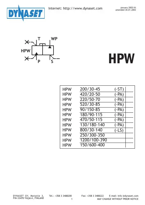
水压卸荷阀
T
WP
P
S
HPW
高 压 工 具
压 力 供 给: MIN. 1,5 BAR MAX 10 BAR
DYNASET OY, Menotie 3, FIN-33470 Ylöjärvi, FINLAND
入 口 管 路: 吸水头最长3米
Tel.: +358 3 3488200 3
柱在水平方向多喷嘴喷头可以到达超过100米的距为了使推进更容易一些启动卷管器使其回转向当到达终点时来自hpw泵液压系统的动力使液压dynasetoy可以提供全面的街道清洗单元当车辆具有合适的液压动力源时基于hpw泵的dynasetkpl街道清洗单元非常轻便的与冲洗功率相关的水的消耗量很低因此路面被清根据液压系统的功率和您所需要的冲洗任务选择合适部件
HPW水口: 吸水口 S, 接吸 水线; 出水口 WP,接 出水 口管线。
PSI bar
P
T
WP
S
WP
带水压卸荷阀的HPW泵
注 意!
根据标记将HPW泵连接到液压系统和水路系统中!
1.如果液压系统与HPW泵的油口接反,不会对泵造成伤害,仅仅是泵不工作。 2.HPW泵的输出功率取决于进油口与回油口的压力差。回油管路中的压力越高,则压力差
就越小,功率就越小。当系统中某个参数变化时,实际应用中应该综合考虑。 3.由于柱塞总成往复运动速度很快(参考工艺参数),由于压力脉动,回油管会有相应的震
动。为了减小压力脉动和回油管震动,推荐用带花纹的布质柔性管作回油管,以保护低压 单元不被破坏,像油散热器等。 4.在把HPW泵连接到液压系统之前,应确保所用各种设备的兼容性。液压系统的压力流量 应该满足HPW泵的要求值。参见工艺参数。
油泵说明书
油泵说明书油泵说明书1. 引言本说明书旨在提供对油泵的详细介绍和使用指南。
油泵是一种用于传输液体的机械设备,广泛应用于工业、农业和汽车等领域。
通过本说明书,您将了解到油泵的工作原理、使用要点和维护保养等相关内容。
2. 油泵工作原理油泵的工作原理是通过机械或电动力驱动,使液体在泵的腔室内产生压力差,进而实现液体的输送。
常见的油泵类型包括离心泵、齿轮泵和柱塞泵等。
2.1 离心泵离心泵利用离心力使液体沿离心方向运动,通过叶片的旋转将液体从进口处抽入泵体,然后通过离心力将液体推至出口处。
离心泵具有简单结构、体积小、输送流量大的特点,广泛应用于工业领域。
2.2 齿轮泵齿轮泵主要由一个或多个齿轮组成,通过齿轮的转动将液体吸入泵的吸入口,并将液体推至排出口。
齿轮泵具有结构简单、运转平稳、噪音小的特点,适用于高粘度液体的输送。
2.3 柱塞泵柱塞泵采用柱塞在柱塞腔中往复运动的方式实现压缩和推送液体。
柱塞泵具有体积小、体积流量可调节的特点,广泛应用于高压输送领域。
3. 油泵使用要点3.1 安装在安装油泵时,请确保以下要点:- 选择合适的安装位置,使油泵稳定安全。
- 根据油泵类型,选择正确的连接方式和管路。
- 清洁并涂抹润滑剂,确保泵体与管路之间密封良好。
3.2 启动与停止在使用油泵之前,请注意以下要点:- 执行正确的启动和停止操作,确保油泵正常运行。
- 遵循厂家提供的操作说明,按照正确的顺序启动和停止油泵。
3.3 使用注意事项在使用油泵时,请遵循以下注意事项:- 关注油泵的工作状态,及时发现异常情况并采取相应的措施。
- 不超负荷使用油泵,以免造成设备损坏或故障。
- 定期清洁和维护油泵,延长其使用寿命。
4. 油泵维护保养为确保油泵的正常运行和延长其寿命,需要进行定期的维护保养工作。
4.1 清洁经常清洁油泵和其附属设备,去除灰尘和杂质。
可以使用干净柔软的布进行擦拭。
4.2 润滑定期检查油泵的润滑情况,确保润滑油的添加和更换。
液相色谱仪高压恒流泵使用说明书
高压注浆泵维修保养说明书
高压注浆泵维修保养说明书天津聚能高压注浆泵维修,说明书,保养:1.泵封存前或调换工作场地需长时间停泵时,必须用清水彻底冲洗泵头工作腔、截止阀、安全阀及吸液、排出管道内的残余介质,擦干并涂上机油,以免产生干固,锈蚀。
2.截止阀工作在介质为水时,可以作辅助调压。
介质中含有固体颗粒时严禁用末调节压力。
3.运转中,柱塞密封若有介质泄漏,说明前端则型密封损坏,必须及时更换.以免引起泄漏及加剧密封损坏。
注意压紧螺母不要调的太紧,以免导向密到抱死柱塞,使填科温升过高。
4.为了保证v型带的传动功率,应定期检查v型带的张紧程度。
安装时,一组皮带应使用具有同一长度公差的v型带,不得将不同长度的v带混合使用。
5.泵运行时一般处于高压状态,需注意安全。
必须配备具有相应知识的专人负责泵的操作、维护与保养,否则极易造成危害。
6.经常检查上、下阀座密封,如有损坏趋势,应立即更换。
否则将进一步引起阀座损坏。
7.安全阀的膜片必须按规定使用,严禁用其他零件代替,否则会造成液力端工作不正常,甚至造成人身、设备损坏。
8.介质必须使用推荐目数(20—22)或以上的过滤网过滤,否则会造成泵系统工作不正常,过粗的颗粒将降低冈座的使用寿命。
9.使用普通电机严荣带压启动,使用调速电机带压启动时,不可提速太快,以免运转超负荷。
10.每次使用停泵后,必须用清水特工作腔内介质清洗干净,以免介质干固,常工作。
11.泵的自吸能力欠佳,需将介质池面与泵的吸液端持乎或例灌。
12.调速电机出厂前均按照规定转速调整好,不得随意调整反馈量来提高转速,否则极易损坏电机及降低密封寿命。
13.最好按照推荐的牌号,使用符合标淮的润滑油,使用不合格的润滑油会降低曲轴的寿命,尤其是过于粘稠且不洁净的润滑油,会对曲轴,轴瓦等零件造成严重的损坏。
野外施工时,地盘不得倾斜放置,否则会影响泵的润滑,影响正常使用。
14.经常检查安全阀体中膜片与高压通道之间是否通畅,防止堵塞。
15.用于柱塞密封处的润滑泊不能断、缺、脏,否则会造成校塞及密封的损坏。
P3000说明书
5
操作指南...................................................................................................................... 10 基本操作 .............................................................................................................. 10 运行和校正菜单(RUN AND CALIBRATE) .................................................. 12 5.2.1 PUMP ........................................................................................................ 12 5.2.2 START........................................................................................................ 13 5.2.3 PURGE....................................................................................................... 13 5.2.4 FLOW CALIBRATE.................................................................................. 13 5.2.5 PRESSURE CALIBRATE ......................................................................... 14 5.3 系统设置菜单(SYSTEM SET) ....................................................................... 15 5.3.1 最大压力(PMAX)设置 ........................................................................ 16 5.3.2 最小压力(PMIN)设置 .......................................................................... 16 5.3.3 冲洗流量(PURGE FLOW)设置........................................................... 16 5.3.4 分析/半制备(ANASYS/SEMI-PREP)设置 ......................................... 17 5.3.5 主从(MASTER/SLAVE)设置 .............................................................. 17 5.3.6 程序或程序链执行次数(REPEAT TIMES)设定................................. 17 5.4 新建程序(NEW PROGRAM)菜单 ................................................................. 18 5.5 装载程序菜单(LOAD PROGRAM) ............................................................... 21 5.6 删除程序菜单(DELETE PROGRAM) ........................................................... 21 5.7 显示梯度(SHOW GRADIENT) ..................................................................... 22 5.8 产品信息(PRODUCT INFORMATION)........................................................ 22 5.8.1 仪器序列号的输入 .................................................................................... 23 5.8.2 装日期的输入 ............................................................................................ 23 5.7.3 退出产品信息输入界面 ............................................................................ 23 5.9 帮助(HELP) .................................................................................................... 23 5.10 P3000 高压输液泵的运行 ................................................................................... 25 5.10.1 泵的启动及停泵 ...................................................................................... 25