NSD电子凸轮(VS-5EX)使用说明
电子控制器手册说明书

UC-RFD52R-E-RF控制单元操作说明EN UC-RF DD52R-E-RF控制单元PLC连接,无线射频数据传输ELESA和GANTER依法保留所有型号的权利。
复制图纸需注明来源。
目录33445556677 1.基本信息1.1 安全预防措施1.2 说明1.3 连接和安装2.说明2.1 连接电源2.2 连接PLC2.3 接口配置2.4 UC-RF和DD52R-E-RF之间的数据交换2.5LED警告灯2.6安全3.技术数据823ENELESA 和GANTER 依法保留所有型号的权利。
复制图纸需注明来源。
1. 基本信息1.1 安全预防措施总论设备的设计和组装符合最新的现行法规。
设备交付给客户时,运行状态良好,满足所有与安全相关的条件。
为了使设备维持这种状态,在安装和使用设备时必须考虑以下因素:- 只能根据预期使用目的使用设备;- 采取与安全和危险有关的所有措施;- 遵守现有手册尤其是相关安全预防措施的规定!确保负责员工阅读并充分了解操作手册,尤其是描述安全预防措施的章节。
作为操作说明的补充,与事故预防和环境保护有关的其他一般或相关法律规定也应当加以考虑并遵守。
本手册是对现有文件(产品信息、安装说明、说明书和目录)的补充。
设备的预期用途设备的预期用途是用于包装、木材、塑料、造纸、玻璃和纺织品等行业的工业过程监控和控制。
设备只能在以下条件使用:- 合适的安装条件;- 符合相关技术数据要求!在本手册规定的说明/参数范围以外使用会造成:-致命的人身伤害;-致命的健康伤害;-物资损失或-设备和财产损失禁止将设备用于:- 爆炸危险区域;- 医疗/生命支持区域和设备。
4EN ELESA 和GANTER 依法保留所有型号的权利。
复制图纸需注明来源。
请勿打开设备或进行任何修改!修改设备会给设备的可靠性带来负面影响,并且可能造成危险!请勿尝试任何维修,请将缺陷设备返回制造商!破坏所交付设备的完整性将导致保修期无效。
EMAX RS2205 Brushless Motor说明书

感谢您购买本产品!无刷动力系统功率强大,错误的使用可能造成人身伤害和设备损坏。
我们强烈建议您在使用设备前仔细阅读本说明书,并严格遵守规定的操作程序。
我们不承担因使用本产品而引起的任何责任,包括但不限于对附带损失或间接损失的赔偿责任;同时,我们不承担因擅自对产品进行修改所引起的任何责任。
我们有权在不经通知的情况下变更产品设计、外观、性能及使用要求。
· 电调与相关连接部件连接前,请确保所有电线和连接部件绝缘良好,短路会毁坏电调。
· 请务必仔细连接好各部件,若连接不良,您可能不能正常控制赛车,或出现设备损坏等其他不可预知的情况。
· 使用此电调前,请认真查看各动力设备以及车架说明书,确保动力搭配合理,避免因错误的动力搭配导致电机超载,最终损坏电调。
· 使用完毕后,切记断开电池与电调的连接。
如电池未断开,即使电调开关处于关闭状态,电调也会一直消耗电能,长时间连接电池最终会被完全放电,进而导致电池或电调出现故障。
我们不对因此而 造成的任何损害负责!· 顶级竞赛专用:内置多种常用模式,即选即用。
(如:零进角 Zero Timing 闪灯模式、STOCK 竞赛模式等)。
电调的设定参数可以导入导出,便于车手相互交流和借鉴彼此的设定。
· 行业首创双开关设计(内置电子开关及外置可拆卸机械开关),外置开关非常适合当一些车子盖上车壳后很难触摸到内置开关的开场合。
· 内置强大的开关模式BEC,最大电流达到6A,且支持 6V和7.4V 切换,轻松驱动各种强力舵机及高压舵机。
· 体积小,更加方便车架布局;重量轻至28g(不含线),低重量为车架的平衡提供了更大的校调空间。
· 独立的参数编程插口,连接LCD编程盒或WiFi模块时无需从接收机中拔出油门线,更加便捷,该插口亦可为外加风扇进行供电。
· 通过编程口外挂一个小巧的WIFI 模块,可以使用手机直接在操控台上设定各项电调参数及浏览数据记录,非常方便。
MotionRT7使用说明书

MotionRT7使用说明书深圳市正运动技术有限公司修订记录日期修订版本修订描述2022.07.11 1.0用户手册的初步创建和制作2022.09.27 1.1内容的修改和补充增加2022.10.12 1.2内容修改目录第一章MotionRT简介 (1)第二章安装驱动 (3)2.1驱动安装 (4)2.2普通网卡安装ECAT总线协议 (14)第三章RT控制台 (17)3.1主界面 (17)3.2UpdateCard界面 (18)3.3License界面 (18)3.4Config界面 (19)第四章功能列表 (20)第五章使用方法 (22)第六章子卡相关指令 (28)6.1CARD_INFO (28)6.2CARD_INFO写入 (29)6.3?*CARD (29)6.4AXIS_ADDRESS (30)6.5REG_CARD (30)第七章注意事项 (32)7.1安装和卸载 (32)7.2UpdateCard更新PCI设备和总线配置保存 (35)7.3License参数配置 (35)7.4Config参数配置 (36)7.5AddECAT总线配置 (36)7.6Start Stop (36)7.7其他 (37)第八章Windows环境配置注意事项 (38)8.1防火墙选项 (38)8.2电源选项 (38)8.3运行库配置 (39)8.4关闭Windows10自动修复功能 (39)8.5关闭Windows10自动更新功能 (40)第一章MotionRT简介MotionRT是正运动实时环境,目前已经开发到第七代。
MotionRT版本规格匹配产品MotionRT1实时运动(RtMotion)实时BASIC(RtBasic)ZMC0系列ZMC1系列ECI1/2/3系列MotionRT2实时运动(RtMotion)实时BASIC(RtBasic)实时梯形图(RtPlc)ZMC2系列MotionRT3实时运动(RtMotion)实时BASIC(RtBasic)实时梯形图(RtPlc)实时组态(RtHmi)ZMC3系列XPLC3系列MotionRT4实时运动(RtMotion)实时BASIC(RtBasic)实时梯形图(RtPlc)实时组态(RtHmi)实时总线(Ethercat,Rtex,XY2)ZMC4系列MotionRT5实时运动(RtMotion)实时BASIC(RtBasic)实时梯形图(RtPlc)实时组态(RtHmi)实时总线(Ethercat,XY2)机器视觉(ZVision)实时Linux(ARM)快速本地LOCAL接口VPLC5系列MotionRT6实时运动(RtMotion)实时BASIC(RtBasic)实时梯形图(RtPlc)实时组态(RtHmi)实时总线(Ethercat)机器视觉(ZVision)VPLC6系列实时Linux(X64)快速本地LOCAL接口MotionRT7实时运动(RtMotion)实时BASIC(RtBasic)实时梯形图(RtPlc)实时组态(RtHmi)实时总线(Ethercat,XY2)机器视觉(ZVision)实时Windows(X64)快速本地LOCAL接口VPLC7系列,普通PC,工控机MotionRT软件特点(1)快速搭建实时应用:相比RTX等实时环境,MotionRT带有易用的实时Basic语言,梯形图,组态等编程语言,快速上手。
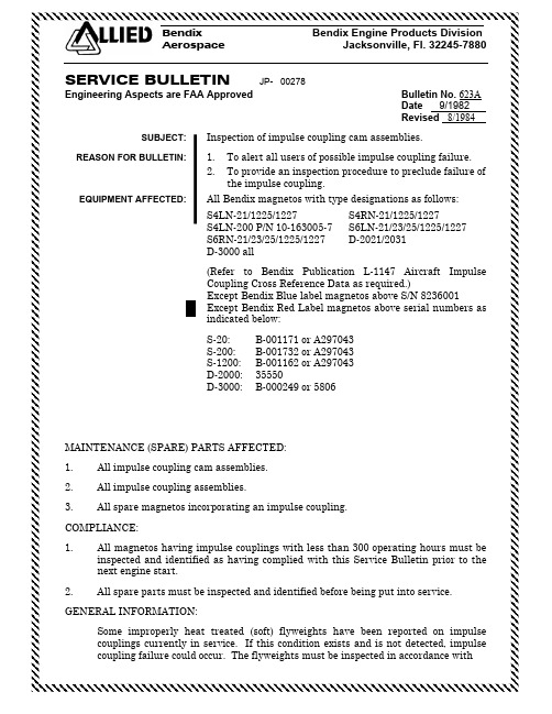
本迪克斯脉冲耦合凸轮组件检查手册说明书

Bendix Bendix Engine Products DivisionAerospace Jacksonville, Fl. 32245-7880 SERVICE BULLETIN JP- 00278Engineering Aspects are FAA Approved Bulletin No. 623ADate 9/1982Revised 8/1984 SUBJECT:Inspection of impulse coupling cam assemblies.REASON FOR BULLETIN: 1.To alert all users of possible impulse coupling failure.2.To provide an inspection procedure to preclude failure ofthe impulse coupling.EQUIPMENT AFFECTED:All Bendix magnetos with type designations as follows:S4LN-21/1225/1227S4RN-21/1225/1227S4LN-200 P/N 10-163005-7S6LN-21/23/25/1225/1227S6RN-21/23/25/1225/1227D-2021/2031D-3000 all(Refer to Bendix Publication L-1147 Aircraft ImpulseCoupling Cross Reference Data as required.)Except Bendix Blue label magnetos above S/N 8236001Except Bendix Red Label magnetos above serial numbers asindicated below:S-20:B-001171 or A297043S-200:B-001732 or A297043S-1200:B-001162 or A297043D-2000:35550D-3000:B-000249 or 5806MAINTENANCE (SPARE) PARTS AFFECTED:1.All impulse coupling cam assemblies.2.All impulse coupling assemblies.3.All spare magnetos incorporating an impulse coupling.COMPLIANCE:1.All magnetos having impulse couplings with less than 300 operating hours must beinspected and identified as having complied with this Service Bulletin prior to the next engine start.2.All spare parts must be inspected and identified before being put into service. GENERAL INFORMATION:Some improperly heat treated (soft) flyweights have been reported on impulse couplings currently in service. If this condition exists and is not detected, impulse coupling failure could occur. The flyweights must be inspected in accordance withthe instructions in this Service Bulletin and if defective (soft) the impulse coupling or cam assembly must be replaced immediately.DETAILED INSTRUCTIONS:(Refer to appropriate Bendix Magneto Overhaul Instructions for the magneto series being inspected.)NOTEThe magneto should be removed from the engine only to the extent necessary to perform the inspection described herein. Depending on the engine application, it may not be necessary to remove the harness from the magneto for the inspection procedure.NOTEAll magnetos with the impulse coupling recessed into the magneto flange must have the impulse coupling removed from the magneto to perform the inspection. This is a bench operation and will require the magneto to be completely removed from the engine and the harness removed from the magneto.CAUTIONWhenever an impulse coupling is removed from a magneto, it must be removed following published procedures, paying strict attention to notes and cautions. Upon reassembly, the castellated nut securing the impulse coupling to the drive shaft must be torqued to 15 ft. lbs. and cotter pinned with new pin. If unable to install pin, torque nut to next castle, not to exceed 25 ft. lbs. and install pin. Removed pin must be discarded and replaced with a new cotter pin (P/N 10-90751-18).1.Following published procedures remove the magneto from the engine.2.Place the magneto in a suitable work stand with the impulse coupling facing up.e finger pressure to push inward on the toe (see figure 1) of each flyweight so thatthe flyweight heel protrudes outward.ing a fine #1, double cut, 1/2 inch wide file, at least 3/32 inch thick, pass the fileacross the heel of the flyweight attempting to remove material. (See figure 1). If the flyweight has been properly heat treated the file will "glide" smoothly over the heel of the flyweight, removing no material. If the flyweight is not properly heat treated (soft), the file will not "glide" easily across the surface of the flyweight heel, and material will be removed.Figure 1Note:XXX indicates heat treated flyweight by lot number5.If an improperly heat treated (soft) flyweight is found, immediately remove andreplace the cam assembly and/or the impulse coupling assembly following procedures in the magneto overhaul instructions, and paying strict attention to notes and cautions.6.Inspect the impulse coupling stop pins for wear and replace as necessary.7.After flyweights and stop pins have been inspected and the impulse couplingreinstalled on the magneto (if removed), identify the magneto by stamping a 1/16 inch letter "F" in the upper right corner of the identification plate to indicate this Service Bulletin has been complied with.8.Reinstall the magneto on the engine following published procedures.9.Make an appropriate engine log book entry, recording magneto serial number, toindicate that this Service Bulletin has been complied with.10.Inspect all spare parts assemblies, including magnetos, following the sameprocedures described in steps 3 and 4 of the Detailed Instructions of this Service Bulletin. If both flyweights are found acceptable, identify the cam assembly by applying yellow Dykem or yellow lacquer to the heel of each flyweight. On magneto spares, stamp a 1/16 inch letter "F" in the upper right corner of the identification plate to indicate this Service Bulletin has been complied with.11.Any cam assembly with an improperly heat treated (soft) flyweight should bereturned to the manufacturer through a currently Authorized Bendix EngineProducts Division Distributor.12. A new method of marking is being implemented to permanently identify heattreated cam assembly flyweights. See figure "1" for location. Pending consumption of current inventory, there will be a mixture of assemblies identified by the following methods.1.Original method ----- Yellow paint (Dykem or Lacquer) on the heel ofeach flyweight.2.New method ----- Stamped numbers as indicated in figure "1" on eachflyweight.WARRANTY CONSIDERATION:None applicable.SPECIAL TOOLS REQUIRED:Refer to applicable manuals.MAN HOURS REQUIRED:1.0 hour per engine with shallow flange mag.1.25 hours per engine with deep flange mag.WEIGHT CHANGE:None。
鲁成雷 凸轮摆杆式攻丝机说明书

Abstract
I
云南农业大学机电工程学院毕业设计说明书
internal threading occupies a large proportion in machining and processing methods within the existing thread machining can not meet today's needs;analysis of existing tapping tapping method derived basic principle; combined with the innovative principles of creative thinking and innovative design, specifically designed to select the best plan ; through different scenarios for impact tappers tapping mechanism research, design tapping mechanism to determine swing cam lever the impact of the detailed design tappers tapping mechanism, and the feasibility of theoretical analysis programs ; on the basis of existing tapping technology, designed cam rod pendulum impact tappers tapping mechanism, programs meet the actual requirements; can be used as the basis for further research, to provide an effective tapping sheet solutions. Keywords: internal thread ; tapping mechanism ; impact tapping ; tapping sheet
VS-5E_NSD 凸轮控制器VARICAM

CAUTION may also result in serious
damage or injury. Be sure to follow the all instructions accompanied by the symbol.
CAUTION
- Do not step on the controller or place heavy objects on the controller; otherwise, it will cause injury.
- Do not block the exhaust port or allow any foreign matter to enter the controller; otherwise, it will cause fire or unit failure.
Thank you very much for purchasing our product. Before operating this product, be sure to carefully read this manual so that you may fully understand the product, safety instructions and precautions.
3. Transport
CAUTION - Do not hold the cable or shaft of ABSOCODER sensor during
transport; otherwise, it will cause injury or controller malfunction.
4. Installation
光陽超級金牌150使用說明書说明书

150機車使用說明書前 言親愛的愛用者:承蒙選購光陽超級金牌150謹致萬分謝忱。
本使用手冊是將光陽超級金牌150之正確操作方法與保養調整方法、要領等加以詳細說明以期耐久安全舒適的使用。
本車型符合機車環保法規排放管制標準,因此合乎低污染、低噪音、省能源的環保要求,雖然本車擁有良好的品質,但還是必需實施定期的保養,才能維持最佳的性能。
為了使您更安全、更舒適之行駛,敬請詳閱本手冊,謹此祝您行車愉快。
本⼿冊之內容與實⾞如有所出⼊者,則以實⾞型式為準。
⾞輛識別號碼資訊1.引擎號碼:本機⾞引擎號碼壓印在左曲軸箱後⽅如圖⽰(1):2.⾞架號碼:本機⾞⾞架號碼壓印在⾞架上如圖⽰(2):重要資訊防竊盜烙碼為防⽌您的愛⾞失竊及配合政府打擊竊盜犯罪政策本機⾞交予顧客前在適當位置烙印防竊盜烙碼(如下圖所⽰),其防竊盜烙碼與引擎號碼相同。
◎本圖為範例,其實際各烙碼位置以實車為準。
全車型在座墊下置物箱後方貼有車輛排氣管制資訊貼紙(如下圖所示)有關貼紙其內容如下:1防竊盜烙碼■⾞輛排氣管制資訊2機⾞資料記錄收集此機型的ECU可收集及記錄該機⾞之運轉相關資訊,⽤以協助⾞輛故障診斷及排除。
這些資訊需使⽤光陽專⽤的診斷⼯具連接⾄機⾞的診斷接頭才能取得,例如執⾏保養檢查或維修程序時。
光陽機型可能感知器及記錄資訊因機種⽽異,但主要資訊為:1.機⾞狀態及引擎性能資訊。
2.機⾞噴射與排放相關資訊。
除⾮有下列情形,光陽機⾞公司不會將這些資訊洩漏給第三⽅:1.經⾞輛使⽤⼈及所有者同意。
2.法律規定必須時。
3.因訴訟⽽提交法院時。
4.因研發之⽤途,且該資訊內容與個別機⾞或⾞主無關時。
.目 錄1.2.4.5.6.7.9.3.5643219878.1.安全駕駛注意事項11駕駛前檢查請詳細熟讀使用手冊及注意事項內容。
駕駛者必須戴安全帽及手套,風鏡等裝備。
妨礙到駕駛安全上的服裝不要穿著。
袖口太寬大,會勾住煞車拉桿、非常危險。
不可有妨礙到煞車拉桿操作之情形。
凸轮定位器说明书

输出响应时间
0.3ms以下
绝缘电阻
电源电压
DC24V
容许电压范围
额定值范围的85~110%
安装方法
嵌入安装
表面安装
嵌入安装
表面安装
消耗功率
约4.5W(8点输出型 DC26.4V时)、约6.0W(16点/32点输出型 DC26.4V时)
编码器输入
连接专用的绝对编码器
输入
输入信号
8点输出型:无 16点/32点输出型:数据库输入1、2、4、原点指定输入、启动输入
种类
■凸轮定位器本体
输出点数 8点
安装方式 嵌入安装 表面安装
16点
嵌入安装 表面安装
32点
嵌入安装 表面安装
输出构成 NPN晶体管输出 PNP晶体管输出 NPN晶体管输出 PNP晶体管输出 NPN晶体管输出 PNP晶体管输出 NPN晶体管输出 PNP晶体管输出 NPN晶体管输出 PNP晶体管输出 NPN晶体管输出 PNP晶体管输出
16⚍䕧ߎ
32⚍䕧ߎ
⬉ᄤ⏽఼
96mm
᭄ᄫ䴶ᵓ㸼
96mm
●使用方便的简单设定 通过一键一功能的简单设定方法,实现出众的使用简便性。初始设 定、现场调整都可轻松进行。
ᡔᴃᣛफ
●大画面显示(带背景灯的负片LCD),运转状态一目了然
大画面 LCD 彩色显示 (当前值=红 35*
1kV(电源输入端子间),1.5kV(导电部端子和裸露的非充电金属部间)
