
高推杯龙头套装不锈钢水盘
Grindmaster-Cecilware CH75N 与 CH100N 华氏暖茶杯热水壶操作手册说

Chinese Hot Tea UrnsCH75N, CH100N SeriesOperator ManualGrindmaster-Cecilware4003 Collins Lane, Louisville, KY 40245 USA Phone: 502.425.4776 Toll F ree: 800.695.4500Fax: 502.425.4664Web:Email:*************)Safety Information.................2Rough-In Drawings.................3Installation...............................4Electrical Specifications...........4Priming....................................5Adjustments. (6)Cleaning...................................6Maintenance...........................8Parts Diagram........................11Parts List.................................14Wiring Diagram (15)Thank you for purchasing this quality urn. For your safety and the safety of others, read all warnings and the operator manual before installing or using the product. Properly instruct all operators. Keep training records. For future reference, record serial number here:Table of Contents©2016 Grindmaster-CecilwarePrinted in USA0516 Form #CW-327-01Part # 390-00071Grindmaster-Cecilware provides the industry’s BEST warranty. Visit for warranty terms and conditions.Model CH100NGB Series Cecilware ®2CAUTIONWARNINGSafety Information2Cecilware ®Chinese Hot Tea UrnsImportant Safety InformationThis is the safety alert symbol. It is used to alert you to potential personal injury hazards. Obey all safety messages that follow this symbol to avoid possible injury or death.For your safety and the safety of others, read all warnings and the operator manual before installing or using the product.DANGER:This term warns the user of imminent hazard that will result in serious injury or death.WARNING:This term refers to a potential hazard or unsafe practice, which could result in serious injury or death.CAUTION:This term refers to a potential hazard or unsafe practice, which could result in minor or moderate injury.NOTICE:This term refers to information that needs special attention or must be fully understood.Chinese Hot Tea Urns Cecilware ®3Rough-In DrawingsCH75N Single 3 Gallon Urn, Adjustable By-pass, and Electro-Mechanical Timer19.34.029.1 3.52.510NN10A14.016.0 5.410.129.14.019.328.010NN 105.43.52.514.010.1CL100N Twin 3 Gallon Urn, Adjustable By-pass, and Electro-Mechanical Timer4Cecilware ®Chinese Hot Tea UrnsElectrical SpecificationsInformation below provided for US models only. Check rating marking on urn nameplate. Consult factory for export model information.InstallationUnpacking InstructionsCarefully unpack the machine and inspect immediately for shipping damage. The packaging may contain unattached parts. Your machine was shipped in a carton designed to give it maximum protection in normal handling. It was thoroughly inspected before leaving the factory. In case of damage, contact the shipper, not Grindmaster-Cecilware.NOTICE:The person installing this appliance isresponsible for ensuring that electric and water connections meet the requirements of the national electric code, national plumbing code, and any local ordinances.See Rough-in Drawings for approximate dimensions and locations of electric and water input.Mechanical InstallationNOTICE:Do not turn thermostat on until allinstallation instructions have been followed.1.Inspect unit to see if any damage occurred inshipment.2.Remove the urn from the packing material. Thefour legs, faucets, and vent cap drain are packed separately with urn.3.Install legs by tilting urn on its side and screwinglegs into urn leg supports until hand tight.4.Carefully right unit and install in its permanentlocation, being sure to leave at least 6" on right side of urn for access to controls. Position urn so that the faucets drip into a drip trough or drain receptacle of some type.5.Level urn by adjusting legs. Then attach faucets andinstall vent cap drain.6.Cover(s) are shipped with knob(s) on inside toprevent damage. Simply unscrew and reverse.WARNING: ELECTRIC SHOCK HAZARD!Installation of this appliance should be performed by CAUTIONThese urns are heavy pieces of equipment. It is Neutral and Ground Wires # 14 AWG min.Note: Field wiring must be suitable for 75° C. Use copper wire only for power supply connections.GROUNDING: ON ALL URNS, CONNECT A GROUND WIRE TO GROUNDING LUG TO COMPLY WITH LOCAL ELECTRICAL CODES (14 AWG MIN. 75° C)Recommended Wire Size For Field-Wiring Urns US models only. Consult factory for export model information..Chinese Hot Tea Urns Cecilware®5Water Hook-upNOTICE: This equipment must be installed in compliance with applicable Federal, State and/or Local plumbing codes having jurisdiction. This product requires an approved back flow prevention water device, such as a double check valve, to be installed between the machine and the water supply. Incoming pressure should be greater than 30 psi and not more than 70 psi.Urn should be connected to cold water supply1.The automatic urn is equipped with a ¼" F larewater inlet fitting which is located on the back of the unit.2.Provide shut-off valve and union in supply line nearurn.3.Minimum inlet pressure at urn should be 30 PSI.4. Maximum inlet pressure recommended at 70 PSI.5. Copper flex tubing should be used for valveconnections.6. To ensure pressure at the urn of at least 30 PSI, use3/8" OD tubing for short runs, 1/2" OD tubing for longer runs, and larger size tubing for unusually long runs. Be sure other appliances will not reduce water pressure excessively.7. Turn on the water supply line and check for leaks. NOTE:For the best tasting tea, add a filtering system to the water supply line to eliminate any taste and/or odor from the water.NOTE:In areas with extremely hard water, a water softener must be installed in order to prevent mineral deposits that could result in malfunctioning of the equipment and in order not to void the warranty. Electrical Hook-upNOTICE:This equipment must be installed in compliance with applicable Federal, State and/or Local electrical codes having jurisdiction. Do not use extension cords. Make sure that the outlet the urn plugs into is grounded.1. Check rating marking on urn nameplate to be sureelectric lines match voltage, phase, and amperage requirements of urn. Select the proper cord and cord grip for electrical rating of the urn.2. Urn body MUST be grounded. A groundingterminal is provided for this purpose.3. Use only copper wire to connect this urn.NOTE: THERMOSTAT MUST BE IN THE "OFF" POSITION.1. Open water supply line valve to urn.2.Turn on or plug in the power supply to the urn.Water compartment will begin to fill automatically.Do not power up the urn when the water line is off.3. Wait until water is visible in center gauge glass (left-hand gauge glass on 3-gallon single urns). Then turn thermostat knob to 10; thermostat pilot light shows heater is on. Urn jacket will continue to fill automatically until water reaches the proper level.4.When indicator on dial thermometer approachesthe "W" in BREW zone, 200° - 205°F (93° - 96°C), urn is ready to brew tea.5.In high altitude locations (over 5000 ft. above sealevel), thermostat may have to be lowered to prevent boiling.6. Brew and discard at least one batch of water intoeach liner. Check that the fill level is correct. See the Adjustments section if changes are needed.WARNING: ELECTRIC SHOCK HAZARD!Installation of this appliance should be performed byInstallation (continued)PrimingWARNING: ELECTROCUTION HAZARD!Never use the ground conductor as a neutral. ThisCAUTION: BURN HAZARD6Cecilware ®Chinese Hot Tea UrnsCleaningAll sanitizing agents in the food zone mustcomply with 21 CF R 178.1010. Sanitize all food dispensing units periodically. All parts to be sanitized must be cleaned first. Cleaning and sanitizing frequency must follow state and local health department regulations.NOTICE:Do not use cleansers, bleach liquids,powders, or any other substance containing chlorine.These products promote corrosion and will pit the stainless steel. USE OF THESE PRODUCTS WILL VOID THE WARRANTY .After Each Brew:1.Dispose of tea leaves and rinse brew basket.Every Day:1.Drain the urn; then run a brew cycle of hot water.After spraying hot water into the liner, thoroughly brush the liner with a long handled brush.2. Drain the water and repeat step one. Run anotherbrew cycle. Brush the liner and drain.3.Wash the wire brew baskets with urn cleaner andrinse thoroughly.Weekly or Bi-Weekly, Depending on Use:1.Fill the urn liners with several gallons of hot water.2.Pour into the liner the recommended concentration of urn cleaning compound. Set the thermostat to high (NO. 10) and then run a brew cycle of hot water.3. Allow solution to remain in the liner for approximately 30 minutes.4. Scrub the inside of both the liner and the cover witha long handled brush.5. Drain the cleaning solution from the liner. Rinse byrunning several brew cycles with the sprayhead centered over the liner. Be sure to drain the rinsewater between cycles.6.Thoroughly clean the faucets.e a long, thin gauge glass brush to clean the teagauge glass. Use the same brush to clean the fitting at the bottom of the liner and the pipe connected to the faucet.8. Reassemble faucets. Fill the liners with hot waterand drain until the liner and all parts are completely rinsed.AdjustmentsThermostat AdjustmentThe Thermostat is factory set for proper dispense temperature of 200°F ± 3°F with the control knob set to the maximum clockwise position. If field adjustments are needed proceed as follows:• To DECREASE temperature, turn the control knob slightly in the COUNTERCLOCKWISE direction. • To INCREASE the water temperature -1.With the Thermostat Knob to its maximum clockwise position, remove the knob and locate the slotted adjustment screw inside the hollow thermostat shaft.ing a narrow-bladed screwdriver, engage slottedadjustment screw and turn it 1/4 turn slowly counter-clockwise. (continued next page)WARNING: SHOCK AND BURN HAZARDThermostat AdjustmentCAUTION: BURN HAZARDThe urn surfaces and water inside jacket are very hot.CAUTION: BURN HAZARDNever remove the faucet when the liner has water orFaucet BodySeat CupX014ABonnetFaucet HandleFaucet Assembly (D017A )Chinese Hot Tea Urns Cecilware ®7Thermostat Adjustment (continued)3.Allow a few minutes for the temperature to reachset level. The Heater Light will go ON, indicating the heating element is activated, wait for it to go OFF,indicating that the water has reached new set temperature.4.Take a temperature reading and repeat if necessary.Mechanical Timer AdjustmentThe factory pre-set mechanical timer can be adjusted for more or less water by following these instructions:1.Remove timer knob and loosen lock nut holdingstop pin.2.To increase volume of water, rotate stop pinclockwise.3.To decrease, rotate counterclockwise. Tighten locknut and replace knob.WARNING: SHOCK HAZARDThermostat BulbCouplingNut CCW - Decrease TemperatureWARNING: SHOCK AND BURN HAZARDTo prevent electric shock and burn hazard all tasks Adjustments (continued)Manual TimerThermostat Assy(L780A )8Cecilware ®Chinese Hot Tea UrnsMaintenanceThe rest of this manual contains information to aid the service technician who is maintaining this equipment.This section has information on performing common service tasks.If you still need help after reading this section, call Grindmaster-Cecilware Technical Service Department,(502) 425-4776 or (800) 695-4500 (USA & Canada only)(Monday through Friday 8 AM - 6 PM EST). Please have the model and serial number ready so that accurate information can be given.Prior authorization must be obtained from Grindmaster-Cecilware for all warranty claims.Grindmaster-Cecilware provides the industry’s BEST warranty. Visit our website at for warranty terms and conditions.To Move the UrnThe urn must be completely drained (jacket and liners)and allowed to cool prior to moving this urn.Spray Arm AssemblyThe new improved spray head system was designed to facilitate easier cleaning and maintenance. The swivel valve has a larger flow opening and the spray head cap is equipped with a stainless steel disc, used to control the flow of water.When ordering replacement parts, be sure to order the correct disc and spray cap for each urn, as shown in Parts Diagram Illustration.• To prevent lime buildup, especially in hard water areas, remove and clean spray head cap and spray head disc frequently.• To clean swivel valve loosen nut and remove spray arm assembly from urn.• Remove sediment by inserting a pipe cleaner through small hole in valve.• If maximum setting of timer fails to deliver enough water, check water pump.If Water Fails To Heat1. Check line fuse or circuit breaker. Replace or resetif necessary.2. Make sure thermostat is in ON position. Ifthermostat pilot light does not come on, replace thermostat. (Refer to instructions below.) If pilot light is on, measure continuity between terminals l and 2 of thermostat, and between terminals 3 and 4. If a resistance is measured, replace thermostat.3. If thermostat is okay, check wiring and repair ifnecessary: if wiring is okay, check heater resistance;if high or infinite, replace as follows:Replacing Heater1. Shut off power and disconnect water supply atelbow. Drain urn.2. Remove one tea gauge glass, faucet, shank, andliner.3. Tilt urn and disconnect wires to heater.4. Remove socket head screw and heater flange andlift heater out.5. Install new heater and reassemble urn.6. Repeat Priming instructions on page 5. NOTE: DONOT TUR N ON THER MOSTAT UNTIL UR N IS PRIMED.Replacing ThermostatThermostat is located in side box of urn. Lift off side box door to gain access to thermostat; then follow instructions below.1. Shut off power, disconnect water supply, and drainurn by opening hot water faucet. When faucet stops running you are ready to remove the thermostat bulb.2. Remove thermostat knob and two screws holdingthermostat in place.3. Disconnect wires from thermostat.4. Pull out thermostat bulb.5. Install new thermostat, push in the new thermostatbulb. Tighten compression nut on thermostat fitting to prevent leaking. 6. Repeat Priming instructions on page 5. NOTE: DONOT TUR N ON THER MOSTAT UNTIL UR N IS PRIMED.If Water from Cold Water Supply Line Does Not Enter Urn1. Check water supply to external shut-off valve.2. Check fuse on rear of side box and replace ifnecessary.3. If water supply and fuse are okay, remove fuse andlift off side box door exposing terminal block and electrical wiring.4. Check dual probe liquid level controller. (SeeComponent Tests )WARNING: SHOCK AND BURN HAZARDWARNING: SHOCK HAZARDWARNING: SHOCK AND BURN HAZARDWARNING: SHOCK HAZARDChinese Hot Tea Urns Cecilware ®9If Water Runs Out At Overflow Drain1. Make sure urn is level and overflow tube is vertical.2. Remove fuse from rear of side box.3. If water continues to flow, solenoid valve is dirty ornot seating properly. Replace solenoid as described below.Replacing Solenoid1. Shut off water supply, remove fuse, and lift off sidebox door.2. Disconnect wires from solenoid: then remove flarenut and unscrew solenoid valve from bracket.3. Install new solenoid and reinstall fuse and side boxdoor.4. If necessary, follow Priming instructions on page5.No Water from Spray Head 1. Check fuse first.2. F or CH urns: Turn brew timer knob clockwise.Replace timer if it does not go on. If timer goes on but pump doesn't, replace pump.Replacing Water Pump1. Shut off water supply and remove fuse. Drain urnto level of water faucet.2. Lift off side box door and disconnect the two pumpwires.3. Loosen union fittings on pump and remove pumpfrom urn. NOTICE: If your urn has older style pump with copper connections, it is imperative that you use a counter wrench when removing and installing pump to avoid damaging copper tubing. DO NOT OVERTIGHTEN.4. Replace pump and follow Priming instructions onpage 5.Component Tests Water Inlet Valve Test1.Turn power OF F. If the water level rises inside apartially filled tank, the Water Inlet Valve is leaking. 2.Disconnect wires from the Water Inlet Valve coil andconnect a 2 wire line cord to the terminals. Plug it into a 115V outlet. If water flows in and stops when you pull it out, the Valve is working fine. Repeat this test a few times. The problem may be in the Probe or Water Level Control Board.3.If the water does not flow in when the cord isplugged into an electrical outlet, the Solenoid coil may be damaged, opened or the valve may have an obstruction preventing the water from flowing in. 4.Clean or replace it.WARNING: SHOCK AND BURN HAZARDTo prevent electric shock and burn hazard, all tasks WARNING: SHOCK HAZARDMaintenance (continued)Hose Nut AssemblyComponent Tests Dual Probe TestIf lack of water persists, check the probe as follows:1.Turn on the power and water supply. Check insidethe tank to make sure the water is below the Probe.Pull the BLUE wire and terminal OFF the Probe rod. 2.If water still does not flow after the wire isdisconnected from the Probe, the problem may be in the Solid State Dual Level Control Board.3.If water starts flowing into the tank, the Probe maybe grounded, due to excessive liming. Check with Ohm meter.4.Clean or replace probe.Dual Probe Liquid Level Controller Test Check the Controller as follows:1.Make sure there is power input to the Controller atthe terminals AC1 & AC2. Your voltmeter should read 115 Volts. It should read the same at terminals AC1 & FILL when the water level is low. This is the output power to actuate the coil of the Solenoid Valve to open it.2.The lack of voltage at terminals AC1 & L-LEVEL orH-LEVEL indicates that the Controller is not working properly.3.Make sure all wire connections are tight, includingground.4.If after this, the Controller is still failing to open theWater Inlet Valve, replace it.10Cecilware ®Chinese Hot Tea UrnsMaintenance (continued)BlueWARNING: SHOCK AND BURN HAZARDTo prevent electric shock and burn hazard, all tasks WARNING: SHOCK HAZARDDisconnect power before attempting any electrical179 Chinese Hot Tea Urns Cecilware®1112Cecilware ®Chinese Hot Tea UrnsParts Diagram (continued)AUTOMATIC COFFEE URNSFAUCET, COFFEE FAUCET, HOT WATERSPRAY ARM ASSEMBLY FE200N, CL200N FE300-NTo p re v ent l ime bui l du p , es p ecia ll y in hard water areas, remo v e and c l ean s p rayhead ca p and s p ray head disc f re q uent l y . To c l ean swi v e l v a lv e, l oosen nut and remo v e s p ray arm assemb l y f rom urn .R emo v e sediment by inserting a p i p e c l eaner through sma ll ho l e in v a lv e .If ma x imum setting o f timer f ai l s to de l i v er enough water, chec k water p um p.TEA CHChinese Hot Tea Urns Cecilware®13Parts Diagram (continued)I dd d thi t l i th f t bl t14Cecilware ®Chinese Hot Tea UrnsParts ListChinese Hot Tea Urns Cecilware®15Wiring DiagramGrindmaster-Cecilware4003 Collins Lane, Louisville, KY 40245 USA Phone: 502.425.4776 Toll F ree: 800.695.4500 Fax: 502.425.4664Web:Email:*************©2016 Grindmaster-Cecilware Printed in USA 0516 Form #CW-327-01Part # 390-00071。
箭牌报价
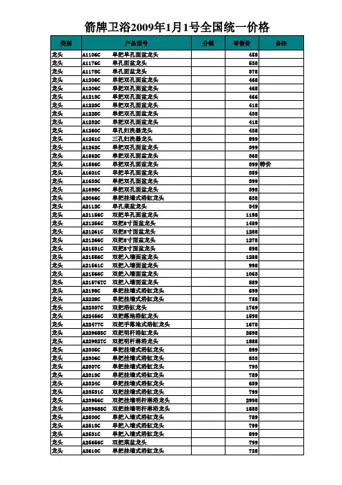
箭牌卫浴2009年1月1号全国统一价格 年 月 号全国统一价格 箭牌卫浴
类别 龙头 龙头 龙头 龙头 龙头 龙头 龙头 龙头 龙头 龙头 龙头 龙头 龙头 龙头 龙头 龙头 龙头 龙头 龙头 龙头 龙头 龙头 龙头 龙头 龙头 龙头 龙头 龙头 龙头 龙头 龙头 龙头 龙头 龙头 龙头 龙头 龙头 龙头 龙头 龙头 龙头 龙头 龙头 龙头 龙头 龙头 龙头 龙头 A26156C 26156C 2633C A2633C 3015C A3015C 3300C A3300C 3313C A3313C 3331C A3331C 3332C A3332C 3333C A3333C 3335C A3335C 3336C A3336C 3338C A3338C 3370C A3370C 3371C A3371C 3500C A3500C 3513C A3513C 53301C A53301C 53901C A53901C 53911TC A53911TC 53912TC A53912TC 81101C A81101C 81117A81117-1C 81120C A81120C 81122C A81122C 81139C A81139C 81170C A81170C A81178C A81172C 81172C 81173C A81173C 81179C A81179C 81180A81180-1C 81180C A81180C 81192C A81192C 81199A81199-1C 81199C A811Байду номын сангаас9C 81201C A81201C 81217C A81217C 81220C A81220C A81235C 81235C 81236C A81236C 81239C A81239C A81272C 81272C 81279C A81279C 81280C A81280C A81292C 81292C 81299C A81299C 81576TC A81576TC 81701C A81701C-A 81701C A81701C-B 产品型号 双把单孔净身龙头 单把挂墙式浴缸龙头 单孔菜盆龙头 单把挂墙式浴缸龙头 单把挂墙式浴缸龙头 单把挂墙式浴缸龙头 单把挂墙式浴缸龙头 单把挂墙式浴缸龙头 单把挂墙式浴缸龙头 单把挂墙式浴缸龙头 单把挂墙式浴缸龙头 挂墙式淋浴龙头 挂墙式淋浴龙头 单把入墙式淋浴龙头 单把入墙式淋浴龙头 双把明杆恒温淋浴龙头 恒温明杆龙头 恒温明杆龙头 恒温明杆龙头 单把单孔面盆龙头 单冷面盆龙头 单孔面盆龙头 单把单孔面盆龙头 单把单孔面盆龙头 单孔面盆龙头 单孔面盆龙头 单孔面盆龙头 单孔面盆龙头 单孔面盆龙头 单把单孔艺术盆龙头 单把单孔艺术盆龙头 单把双孔面盆龙头 单把单孔加高面盆龙头 单把单孔面盆龙头 双孔面盆龙头 单把双孔面盆龙头 双孔面盆龙头 单把双孔面盆龙头 单把双孔面盆龙头 单把双孔面盆龙头 单把双孔面盆龙头 单把双孔面盆龙头 单把双孔面盆龙头 单把双孔面盆龙头 单把单孔面盆龙头 单把入墙式面盆龙头 单孔面盆感应龙头 单孔面盆感应龙头 分销 零售价 1288 732 439 599 599 399 678 656 668 689 668 638 688 537 537 1898 1198 2398 2368 438 299 498 499 393 539 519 479 636 469 788 563 623 799 633 549 389 598 498 498 598 488 758 688 998 699 488 1898 交流 1788 直流 备注
铂浪高产品卖点
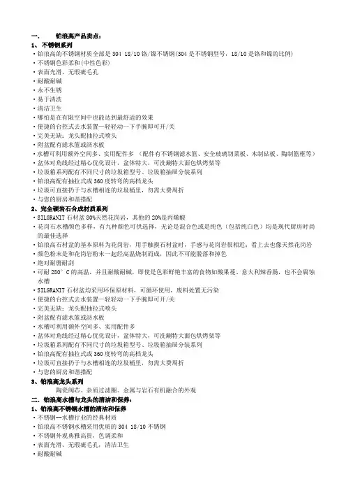
一.铂浪高产品卖点:1、不锈钢系列·铂浪高的不锈钢材质全部是304 18/10铬/镍不锈钢(304是不锈钢型号,18/10是铬和镍的比例)·不锈钢色彩柔和(中性色彩)·表面光滑、无瑕疵毛孔·耐酸耐碱·永不生锈·易于清洗·清洁卫生·哪怕是在有限空间中也能达到最舒适的效果·便捷的台控式去水装置—轻轻动一下手腕即可开/关·完美无缺:龙头配抽拉式喷头·附盆配有滤水篮或沥水板·水槽可利用额外空间多、实用配件多(配件有不锈钢滤水篮、安全玻璃切菜板、木制砧板、陶制篮框等)·盆体对角线经过精心优化设计,盆体特大,可洗涮特大面包烘烤架等·垃圾箱系列配有不同尺寸的垃圾箱型号、垃圾箱抽屉分装系列·铂浪高配有抽拉式或360度转弯的高档龙头·垃圾可直接扔于与水槽相连的垃圾桶里,勿需大费周折·与您的厨房和谐搭配2、完全硬岩石合成材质系列·SILGRANIT石材盆80%天然花岗岩,其他的20%是丙烯酸·花岗石水槽颜色多样,有九种颜色可供选择,无论是混合色或是纯色(包括纯白色)均是现代厨房时尚的最佳选择·铂浪高石材盆的基本原料为花岗岩,用手触摸石材盆时,手感与花岗岩很相近;看上去也像天然花岗岩·颜色粉末是和花岗岩粉末一起经高温烧制而成,因此不可能脱落和掉色·绝对耐麿耐刮·可耐280°C的高温,并且耐酸耐碱,即使是色彩鲜艳丰富的食物如酸果蔓、意大利辣香肠,也不会腐蚀水槽·SILGRANIT石材盆均采用环保原材料,可循环使用,废料处置无污染·便捷的台控式去水装置—轻轻动一下手腕即可开/关·完美无缺:龙头配抽拉式喷头·附盆配有滤水篮或沥水板·水槽可利用额外空间多、实用配件多·盆体对角线经过精心优化设计,盆体特大,可洗涮特大面包烘烤架等·垃圾箱系列配有不同尺寸的垃圾箱型号、垃圾箱抽屉分装系列·铂浪高配有抽拉式或360度转弯的高档龙头·垃圾可直接扔于与水槽相连的垃圾桶里,勿需大费周折·与您的厨房和谐搭配3、铂浪高龙头系列陶瓷阀芯、杂质过滤圈、金属与岩石有机融合的外观二.铂浪高水槽与龙头的清洁和保养:1、铂浪高不锈钢水槽的清洁和保养·不锈钢--水槽行业的经典材质·铂浪高不锈钢水槽采用优质的304 18/10不锈钢·不锈钢外观典雅高贵,色调柔和·表面光滑、无瑕疵毛孔,清洁卫生·耐酸耐碱·永不生锈·易于清洗·正确地清洗保养您家的水槽可以延长水槽的使用寿命,并使水槽永远亮丽如新。
科勒公司98423T单把碗盆龙头(高出水口)安装说明书
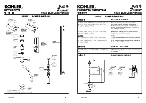
98423T 单把碗盆龙头(高出水口)INSTALLATION INSTRUCTIONS 安装说明书Single Lever Lavatory FaucetSingle Lever Lavatory FaucetSERVICE PARTS 零 件 图880096Hose 软管**订购时请说明颜色编号**Color code must be specified when ordering1142103**Click Drain 弹跳式排水组件1102890**Stopper 止水塞1056867**Nut 螺母1014338Valve 阀芯3008414Valve Seat 阀座871472O-ring O 型圈871472O-ring O 型圈1049041Washer 垫片834704Mountiong Hardware Kit 安装组件1069787**Areator 起泡器1022689**Bonnet 阀帽1032012**Plug Button Kit 塞扣组件1048356**Sculpted Lever Handle Kit波浪型把手组件1049039**Straight Lever Handle Kit 杆型把手组件76713Screw 螺钉1102891Washer 止水垫1102892Piston Kit 活塞组件1032012**Plug Button Kit 塞扣组件76713Screw 螺钉安装步骤INSTALLATIONHow To Install The FaucetInstall the mounting stud(1) into the faucet body base. Stick washer(2) under the body assembly. Insert the flexible supply hoses(3) into the lavatory hole.From underside of lavatory, placebracket(4, rubber washer is on the top) and nut(5) onto mounting stud. Position the faucet so that spout points to the front. Tighten nut to secure faucet to lavatory.Attach the hoses to water supplies. The hose with ‘COLD’ label connects to cold water, the other hose connects to hot water.如何安装水龙头将固定螺栓(1)安装安装到水龙头的底部,把垫圈(2)粘到水龙头底部,将软管(3)插入洗脸盆的安装孔中。
卡萨帝暖杯碟机 C7WD14BG说明书
家用暖杯碟机WD14MG C7WD14BG 系列 系列HEALTHY&WARMTH HEALTHY WARMTH卡萨帝为了精确实现您的格调生活,对其家族每一类产品都赋予了专属的境界理念。
本产品为您带来的是洁净厨房。
12关于本产品的安全注意事项 .........................................................3本产品的安装 . (6)安装前的准备 .......................................................................6安装的步骤 ...........................................................................6电气连接 ..............................................................................7本产品外观及部件介绍 .. (8)各部件构成 ...........................................................................8控制旋钮 ..............................................................................8本产品的主要功能介绍 .. (9)暖杯碟机工作原理 ................................................................91.首次使用之前的准备 .....................................................92.使用暖杯碟机步骤 .........................................................93.温度选择开关 ..............................................................104.各类附加用途 ..............................................................105.加热时间参考 ...............................................................116.承载能力参考 ...............................................................11本产品的日常保养与维护 ...........................................................12清洁保养准备 .....................................................................12清洁各个部件 .....................................................................12有疑问?先看这儿! ..................................................................13保修说明 ....................................................................................14技术数据 . (1617)产品中有害物质名称及含量3尊敬的卡萨帝用户:您好!感谢您使用卡萨帝产品,为了您能更好的阅读本说明书和使用本产品,防止人身伤害及物品损坏事故,请务必仔细阅读并遵守本说明书中有以下标志符号的内容。
商品分类之百货

制冰压汁机0729
平煎锅0730
中式炒锅0731
煮锅0732
非金属锅0733 调理容器0734
特殊烹调用具0735
压力锅073502 蒸锅073503 特殊烹调用具0735 闷烧锅073504 蒸笼073505 压力锅配件073506 一般水壶073601 水壶0736 叫壶073602 无盖垃圾桶073701 垃圾桶0737 有盖垃圾桶073702 脚踏垃圾桶073703 百货部 家庭用品07 水桶073801 水桶/水瓢0738 脸盆073802 水瓢073803 手套、围裙073901 抹布073902 手套/擦洗用具0739 菜瓜布073903 钢丝球073904 其它擦洗用品073905 扫把074001 垃圾斗074002 垃圾斗组074003 地板刷074004 打扫用具0740 拖把074005 拖把头074006 除尘用品074007 玻璃清洁器074008 打扫配件074009 金属衣架074101 衣架0741 塑料衣架074102 木制衣架074103
免洗碗0714 便当盒0715 免洗盘0716 免洗杯0717
百货部 家庭用品07
一次性配件0718
保鲜膜/铝箔0719 烤肉用品0720 木碳0721 烤肉配件0722 厨用便当盒0723
厨用保鲜盒0724
保温容器0725
保温容器0725
滤水器0726
烹调用具0727
百货部 家庭用品07
厨房整理用具0728
棋类091001 扑克091002
百货部 休闲用品09
室内游戏0910 男/女包0911 包0912
麻将、牌九091003 其它室内游戏091004 旅行袋091201 折叠袋091202 软拉杆箱091301 硬拉杆箱091302 软行李箱091303 硬行李箱091304 行李车091305
利奥 ALEO 感应梳洗脸盆龙头 安装说明书
手动操作阀杆
手动操作
□在断电的情况下,感应功能将失效,可以手动操作电子阀上的手动操作阀杆。 □用硬币顺时针转动手动操作阀杆到位启动手动操作功能,逆时针转动到位关闭手动操作功能。 □一旦打开手动操作功能,水龙头仅能通过手动控制。
1486776-T2-B
2
安装步骤
3 21 5
如何安装水龙头
□将垫片(1)穿过牙管(2)嵌入到水龙头本体(3)底部的槽中。
起泡器
供水软管 供水阀
重锤 蓝色端口和接头
□检查并确保所有衔接处都已拧紧。
□确保把手在关闭位置。
□打开主水源和排水系统。
□检查并修理有漏水的接口。
□将起泡器取下。打开水龙头,让水流约一分 钟以清除杂质。冲洗起泡器。关闭水龙头,重 新装回起泡器。
5
维护与保养
26
如何清理排水器
27
□逆时针旋下止水塞(26),取出并清理止水垫
8
21 20
支架
23
22
如何安装电子阀
重要!限流风险。安装过程中,出水软管(8)不得绷紧或打结。
注意:用手拧紧出水软管接头。不要使用钳子或扳手。 □将出水软管拧到电子阀进水口(20)。 □将电子阀(21)套在已安装好的支架上。 □将花洒软管(22)连接到电子阀出水口(23)。确保卡入到位,连接牢固。
安装说明书
安装之前
29008T-4 感应梳洗脸盆龙头
利奥
ALEO
所有的资料是按最新出版的产品资料编写而成。科勒公司保留任何时候不经通知即可改变产品特性、包装或产 品可供类型的权利。
说明书包括重要的安装、保养及清洁方面的内容,请把这些资料交给用户阅读。
注意事项:
1.一定要先彻底冲洗供水管以清除管道中的杂质。 2.如果是安装新的脸盆,可将水龙头先装到脸盆上。 3.花洒最高工作压力:0.5MPa(5bar)。水压超过0.5MPa(5bar)时必须安装减压阀。花洒最高工作温度及环境温 度:60ºC。请特别注意花洒同花洒连接的臂管须远离加热器,否则可能损坏花洒及其密封件,甚至对使用者造 成伤害。
Contour 冷水泉泉机双喇叭和水瓶填充器安装说明书
Contour™ Refrigerated Fountainswith Double-Bubbler™ and HydroBoostNOTE: It is common practice to ground electrical hardware such as telephones, computers and other devices to available water lines. This can, however, cause electrical feedback in the plumbing circuit, which2000000499 (Rev. A - 01/22 )Page 12000000499 (Rev. A - 01/22 )Page 22000000499 (Rev. A - 01/22 )Page 32000000499 (Rev. A - 01/22 )Page 4CHILLER OUTLET8STRAINERTO BUBBLER8TO BOTTLEFILLERFigure 4 – HTHBWF-HRF-RF Filter Mounting(not required with HTHB-HRF-RF)2000000499 (Rev. A - 01/22 )Page 5Figure 7 – Fountain InstallationFigure 8 – Lower Panel Installation82NutNut4,5,6,7,81Reset Switch10. Install fountains with (4) 5/16-18 HHMS, (4) 5/16-18 nuts (from original installation) (Fig. 7). Connect the ¼” water lines from the fountain to the remaining opening on the tee at the remote chiller (cut lines to fit as needed), (Test fit refrigerated panel to make sure there is a tight joint between it & the main panel before fully tightening mounting screws.)11. Attach waste tubes (1-1/4” O.D.) to 1-1/4” O.D. slip trap. Trap on the bottle filler side must be 1-1/2” O.D. (Traps and connec- tion fittings provided by others).12. Drill a 5/32” (.156”) diameter mounting hole in right hand frame to secure the lower right corner of the upper panel.• Center the hole in tab opening.• Secure the panel to the frame with (screw in kit Item 8).13. Make final water supply connections. Turn on water supply, check for leaks. Repair leaks as required.• These products are designed to operate on 20-105 PSI supply line pressure. If inlet pressure is above 105 PSI, a pressure regulator must be installed in the supply line. • (Caution: Any damage caused by connecting these products to a supply line with pressure lower than 20 PSI or higher than 105 PSI IS NOT covered under warranty.)14. Make electrical connections to the bottle filler and remote chiller. The LCD Bottle counter should illuminate. Refer toBF11 Program instructions for additional details on Bottle Filler setup.15. Verify proper dispensing from the bottle filler by placing a cup, hand or any opaque object in front of sensor area and verify water dispenses. Note: the first initial dispenses might have air in the line which may cause a sputter. This will be eliminated once all air is purged from the line. A steady stream of water assures all air is removed. The sensor has a 20 second maxi- mum ON time. It may be necessary to step away from the beam a few times to purge all air. Check for leaks. 16. Reconfirm the installation has no leaks. Install the lower (louver) panel.8 See Note 12NOTE: The following items are not used with the converted installation: – One Fountain Assembly – Wall Frame - Left Side – Upper Panel – Lower (Louver) Panel3VERIFY CONTROL BOARD SOFTWARE1) To verify the software program of the control board the unit willneed to be shut down and restarted. The chiller (if present) doesnot need to be shut down and restarted.2) Shut down the unit by unplugging the power cord from the walloutlet or switching off the circuit breaker to the unit.3) Restart the unit by plugging the power cord back into the walloutlet or by switching on the circuit breaker to the unit.4) Upon start up, the bottle count display will show the softwaredesignation of BF11 or BF12.ACCESSING THE PROGRAMMING BUTTON1) To access the program button, remove the bottom lower louveredpanel (Fig. 7) by removing the lower panel screws. Reset button is located on the mounting bracket.RESET THE FILTER MONITOR1) Instructions apply to filtered units only.2) Depress the program button for approximately 2 seconds until thedisplay changes then release. The display will change and scrollthrough two messages:“RST FLTR” – Reset Filter Monitor“SETTINGS” – System Settings Sub MenuIf the program button is not pushed again the display will scroll through the two messages above for three cycles and then default back to bottle count and be back in run mode.3) When the display changes to “RST FLTR”, depress the buttonagain. The display will change to show “FLTR =”. Depress thebutton again and the display will show “FLTR =0”4) The Green LED should be illuminated indicating that the visual filtermonitor has been reset.SETTING RANGE OF THE IR SENSOR WHERE APPLICABLE 1) Depress the program button for approximately 2 seconds until thedisplay changes then release. The display will change and scroll through two messages:“RST FLTR” – Reset Filter Status LED“SETTINGS” – System Settings Sub MenuIf the program button is not pushed again the display will scroll through the two messages above for three cycles and then default back to bottle count and be back in run mode.2) When the display changes to “SETTINGS”, depress the buttonagain. The display will change to show“RNG SET” - Range set for IR sensor.“UNIT TYP” - Type of unit (REFRIG or NON-RFRG)“FLT SIZE” - Select filter capacity“RST BCNT” - Reset bottle count3) When display shows “RNG SET” push program button once thedisplay will show current value (can be 1 – 10) e.g. “RNG = 3”.4) Once display shows current value push the program button to scrollthrough value of 1 – 10. Select the desired range setting, "1" being closest to sensor and "10" being farthest away.5) Once range is selected allow approximately 4 seconds to pass andthen the display will go back to bottle counter and be in run mode. 6) Test bottle filler by placing bottle or hand in front of sensor to makesure water is dispensed.SETTING UNIT TYPE1) Depress the program button for approximately 2 seconds until thedisplay changes then release. The display will change and scroll through two messages:“RST FLTR” – Reset Filter Status LED“SETTINGS” – System Settings Sub MenuIf the program button is not pushed again the display will scrollthrough the two messages above for three cycles and then default back to bottle count and be back in run mode.2) When the display changes to “SETTINGS”, depress the buttonagain.The display will change to show“RNG SET” - Range set for IR sensor.“UNIT TYP” - Type of unit (REFRIG or NON-RFRG)“FLT SIZE” - Select filter capacity“RST BCNT” - Reset bottle count Continued from below:3) W hen display shows “UNIT TYPE” push program button once thedisplay will show current value. C an be REFRIG or NON-RFRG4) Push button once to change value. Once value is s elected the display will show the new value. (Can be REFRIG or NON-RFRG) “REFRIG“ - stands for refrigerated product. In this setting the flow rate is estimated at 1.0 gallon per minute.“NON-RFRG“ - stands for nonrefrigerated product. In this setting theflow rate is estimated at 1.5 gallons per minute. Both “REFRIG“ and“NON-RFRG“ simulate 1 bottle equal to 20 oz.5) A llow approximately 4 seconds to pass and the display will return to bottle counter and be in run mode.RESETTING BOTTLE COUNT1) Depress the program button for approximately 2 seconds until thedisplay changes then release. The display will change and scrollthrough two messages:“RST FLTR” – Reset Filter Status LED“SETTINGS” – System Settings Sub MenuIf the program button is not pushed again the display will scroll through the two messages above for three cycles and then default back to bottle count and be back in run mode.2) When the display changes to “SETTINGS”, depress the button again. The display will change to show:“RNG SET”- Range set for IR sensor.“UNIT TYP” - Type of unit (REFRIG or NON-RFRG)“FLT SIZE” - Select filter capacity“RST BCNT” - Reset bottle countIf the button is not pushed again the display will scroll through the four messages above for three cycles and return to run mode.3) W hen display shows “RST BCNT” push program button once thedisplay will show current value, e.g. “0033183”.4) Once display shows current value push the program button once more to reset back to 0. The display will show BTLCT = 0 for approximately 2 seconds and then return to run mode showing 00000000 bottles. NOTE: Once the bottle count is reset to zero there is no way to return to the previous bottle count.5) T esting the bottle counter:REFRIG units: Place bottle or hand in front of sensor for approximately9 seconds to see bottle counter count 00000001,(This is based on filling a 20 oz. bottle).NON-RFRG units: Place bottle or hand in front of sensor for approximately 6 seconds to see bottle counter count 00000001,(This is based on filling a 20 oz bottle).SETTING FILTER CAPACITY1) Depress the program button for approximately 2 seconds until thedisplay changes then release. The display will change and scroll through two messages:“RST FLTR” – Reset Filter Status LED“SETTINGS” – System Settings Sub MenuIf the program button is not pushed again the display will scroll through the two messages above for three cycles and then default back to bottle count and be back in run mode.2) When the display changes to “SETTINGS”, depress the button again. The display will change to show:“RNG SET“- Range set for IR sensor.“UNIT TYP“ - Type of unit (REFRIG or NON-RFRG)“FLT SIZE” - Select filter capacity“RST BCNT“ - Reset bottle countIf the button is not pushed again the display will scroll through the four messages above for three cycles and return to run mode.3) W hen display shows “FLT SIZE” push program button once. The display will show current value. Can be 3000GAL or 6000GAL.4) Push program button again to display the desired “FLT SIZE”.5) Allow approximately 4 seconds to pass and the display will return tobottle counter and be in run mode.BF11 - BF12 PROGRAMSETTING THE CONTROL BOARD2000000499 (Rev. A - 01/22 )Page 61333 BUTTERFIELD ROAD SUITE 200 DOWNERS GROVE, IL 60515630.574.3500Figure 10 – Water Supply ConnectionsNOTE: WATER FLOWDIRECTIONSERVICE STOP(NOT FURNISHED)1/4” O.D. TUBE3/8” O.D. UNPLATEDDO NOTActuation of Quick Connect Water Fittings: Cooleris provided with lead-free connectors which utilize ano-ring water seal. To remove tubing from the fitting,relieve water pressure, push in on the gray collar whilepulling on the tubing. (See Fig. 11) To insert tubing,push tube straight into fitting until it reaches a positivestop (approximately 3/4”).OPERATION OF QUICK CONNECT FITTINGSOPERATION OF QUICK CONNECT FITTINGS2000000499 (Rev. A - 01/22 ) Page 7。
Moen 3 11 16 寸手柄和 93 毫米到 12 1 8 寸的水龙头系列说明书
3 11/16"93mm12 5/8"321mm12 1/16"306mm2 3/8"61mmQuarter-TurnFinger Hook3/8" NPT x 26" RiserCerama Cartridges w/Check Valves &Items Not Shown For ClarityColor Coded IndexesAdjustable From Lever Handles w/ [197mm to 210mm]7 3/4" to 8 1/4" 2" [51mm]Flanges w/1/2" NPT Female Inlets8"203mm __________________________Date_________Product Specifications:Model No.Item No.T&S BRASS AND BRONZE WORKS, INC.B-0131-CR-BModel Specified_____________________ Quantity______ Customer/Wholesaler______________________________ Contractor_______________________________________Travelers Rest, SC 296902 Saddleback Cove / P.O. Box 10888" Wall Mount Pre-Rinse Unit w/ Lever Handles, 1/2" NPT Female Inlets,Architect/Engineer_________________________________Travelers Rest, SC: 800-476-4103 • Simi Valley, CA: 800-423-0150 • Fax: 864-834-3518 • This Space for Architect/Engineer ApprovalJob Name Product Compliance:ASME A112.18.1 / CSA B125.1B-0109-016" Wall BracketSteel Hose Assembly Flexible Stainless 20"JointSwivel 360B-01071.15 GPM Spray Valve 29 7/8"759mm3/4"19mmITEM NO.SALES NO.DESCRIPTION1B-0107 1.15 GPM Spray Valve 2010476-45#27 Washer3000907-45Spray Valve Hold Down Ring4B-0020-H 20" Flexible Stainless Steel Hose w/ Grip Handle5002882-4012" "L" Tube Assembly 6B-0109-016" Wall Bracket 7004R Finger Hook 8000373-403/8" NPT x 26" Riser 9EZ-K EasyInstall Kit 10001065-45O-ring11014200-45Star Washer, Anti-Rotation12018506-19NS Blue Button Index, Press-in 13000925-45Lab Handle Screw14012447-25NS Quarter-Turn Cerama Cartridge w/Check Valve, Handle, Blue Index &Screw, LTC15012395-25NS Quarter-Turn Cerama Cartridge w/Check Valve, LTC1600AA 1/2" NPT Female Eccentric Flange 17001019-45Coupling Nut Washer18012394-25NSQuarter-Turn Cerama Cartridge w/Check Valve, RTC19012446-25NS Quarter-Turn Cerama Cartridge w/Check Valve, Handle, Red Index &Screw, RTC20001638-45NS Lever Handle (New Style)21001193-19NS Red Button Index, Press-in 2012342567891011121314151617181921Model No.Item No.T&S BRASS AND BRONZE WORKS, INC.Travelers Rest, SC: 800-476-4103 • Simi Valley, CA: 800-423-0150 • Fax: 864-834-3518 • B-0131-CR-BTravelers Rest, SC 296902 Saddleback Cove / P.O. Box 1088ASME A112.18.1 / CSA B125.1Product Compliance:8" Wall Mount Pre-Rinse Unit w/ Lever Handles, 1/2" NPT Female Inlets, Product Specifications:。
九阳 加热破壁料理机 NinjaH5H6 使用说明书
21 在产品工作过程中若有液体溢出,请及时 清理,避免液体溢出至连接器处。
22 如果刀片被卡住,请先关闭开关、断开电 源,再进行清理,以免发生伤害事故或损 坏产品。
下厂文件 V1-190103
第二章:产品部件名称
注意:产品图片请以包装内 实 物 为 准! (H5 没 有 冷 杯 组件 )
A B C D
E
7
I
J
K A F G H
第二章:产品部件名称
部件名称 A 投料盖 B 热杯杯盖 C 热杯杯盖密封圈 D 不锈钢搅拌杯(热杯) E 主体 F 冷杯杯盖 G 冷杯杯盖密封圈 H 玻璃搅拌杯(冷杯) I 量杯 J 搅拌棒(刮刀) K 清洁刷
√ • 制作酱料时建议食材量为 500g。
用于快速
清洗杯体
√
内壁
• 清洗杯体时建议加入水量
√
不 超 过 1750mL, 不 低 于
500mL。
用于设定
DIY 加热、 DIY 粉碎时
√
间
• 加热工作时间范围为 5 分 钟至 4 小时;初始为 30 分 钟,1 小时以内,每按一下 增加 5 分钟,1 小时以上, 每按一下增加 30 分钟,长 按可持续增加,循环可调;
15 产品工作时,严禁移动产品、提起杯体或 触碰刀片、电机等可动部件,以免造成人 身伤害或损坏产品。
16 在拆、装、调校或清洗本产品的任何部件 之前,请关闭开关、断开电源,以免产品 漏电或意外启动。
17 产品工作时,严禁打开杯盖添加食材,以 免发生喷溅烫伤。可打开杯盖中间的投料 盖,通过投料孔添加食材。(如图二)