
ATS控制器操作说明
A T S控制器操作说明 Hessen was revised in January 2021
SK400系列双电源自动转换控制器操作说明
1操作
操作面板
按键功能描述
I路手动合闸键手动状态下,按键,I路接通负载。
分闸键手动状态下,按键,断开I路/II路负载。
II路手动合闸键手动状态下,按键,II路接通负载。
手动设置键按键,设置控制器为手动状态。
自动设置键按键,设置控制器为自动状态。
试机键按键,可以直接进入试机界面。
菜单键/确认键按键,进入菜单界面,长按键退出当前操作,回到主界面显示。
当控制器故障报警时,长按键,可消除故障报警。
翻屏键/增加键切换屏幕显示界面。
在参数配置界面调整参数时为数值增加键。
主菜单界面
在主界面下按下键,可进入主菜单界面。
日期时间设置
10-06-25 (2) 10:00
按键选择不同的参数行(当前行反黑),再按
进行确认,可进入相应的显示界面。
2 参数配置
在主界面下,按键,选择1. 参数设置,再按
键确定,则进入参数配置口令确认
界面。
按
键输入对应位的口令值0-9,按
键进行位的右移,在第四位上按
键,进行
口令校对,口令正确则进入参数主界面,口令错误则直接退出返回主界面。
出厂默认口令为:1234。
按键可进行参数配置上下翻屏操作,在当前的配置参数屏下按
键,则进入当前参数配置模式,屏幕第一行与当前值的第一位反黑显示,按
键进行
该位数值调整,按键进行移位,最后一位按
键确认该项设置。
若设定的数值在范
围内,则该值被保存到控制器内部的FLASH 。
若超出范围,则不能被保存。
在参数配置
界面,长按
键,可直接退出该界面,回到主显示界面。
参数配置表
主要参数配置项目表
参数名称
整定范围
默认值 描 述
07 开关转换间隔 (0-9999)秒 1 从一路分闸到二路合闸,或从二路分闸到一路合闸中间的延时等待时间
24 电流互感器 变比
(5-6000)/5 500 电流互感器参数 25 额定负载电流 (5-5000)A 500 机组额定电流 28 设备编号 (1-254) 1 RS485通讯地址
29 口令设置 1234 配置参数所需的密码值 33
切换优先级 选择
(1-3)
1
1.一路切换优先
2.二路切换优先
3.切换无优先
3 日期时间设置
在主界面下,按
键,选择3.日期时间设置,再按
键确定,则进入日期时间设置界面。
如图:
参数设置 2.定时开机
3.日期时间设置
4.语言/Language
5.控制器信息
控制器信息
一个分断位
一路切换优先
2009-10-11
按键输入对应位的数值0-9,按键进行位的右移,右移到最后一位时按键,
则可以更新控制器日期与时间。
日期时间设置格式:年-月-日 (星期) 小时:分钟
4 控制器信息
在主界面下,按键,选择5.控制器信息,再按键确定,则进入控制器信息界
面。
如下图:
显示内容包括控制器当前分断位设置和切换优先选择及控制器版本、日期。
长按
键,可直接退出该界面,回到主显示界面。
5 ATS 操作运行
手动操作运行
按下
键,手动状态指示灯亮,控制器处在手动状态。
按下
键,一路合闸继电器输出,若一路合闸状态输入检测有效,一路电源带
载指示灯亮,一路接通负载。
按下
键,二路合闸继电器输出,若二路合闸状态输入检测有效,二路电源带
载指示灯亮,二路接通负载。
按下
键,一路/二路分闸继电器输出,若一路/二路合闸状态输入检测无效,
一路与二路电源带载指示灯灭,负载断开一路与二路电源。
*1 *1:对于无分断位类型的ATS ,按
键无效。
自动操作运行
按下键,自动状态指示灯亮,控制器处在自动状态,控制器可自动切换一路或二
路。
施耐德 双电源MG ATS用户手册

ATS技术操作规程一.送电前检查1.检查接线是否正确检查ACP(辅助控制板)与BA或UA(控制器)之间9#.10#连接端子对应是否正确;检查ACP上P25M与断路器之间接线是否正确(详见“ATS接线”单页)2.检查BA或UA控制器顶部17#.18#;20#.21#端子是否安装,17#.18#;20#21#已分别短封好;3.检查断路器电操左下方的手动(manu)和电动(auto)切换拨钮是否在“auto”位置;4.检查电操与BA或UA控制器的操作电压是否一致(220V~或380V~);5. 检查ATS装置无异物;6.检查ACP上P25M是否已在合闸位置。
二.操作试验1.预设电源转换时间: 通过控制器右上方时间整定钮调整;2.将BA或UA控制器上的选择开关置于“STOP”位置,将ACP上“N(工作电源)”及“R(备用电源)”侧P25M分别合闸(两台断路器电操储能)。
3.将BA或UA控制器上的选择开关转到“auto”位, N断路器合闸,BA或UA“N”、“R”侧ON或OFF指示断路器的合分状态。
观察控制器指示与断路器电操上的ON. OFF位置应一致;4.将ACP上N侧P25M开关分断模拟电源故障, 此时N侧断路器分断;R侧断路器合闸(系统自动转换到备用电源R侧); 合上N侧开关,电源应自动恢复到主电源(N)侧合闸---自投自复功能;5.将N侧断路器下端的故障试验推杆按入(模拟负荷故障),N侧断路器断开BA或UA控制器的N侧Fault指示灯亮(红色),电源并不转换到备用侧; 手动拨N侧断路器电操的储能手柄2次,(N侧断路器储能、合闸)故障复位,控制器N侧Fault指示灯灭, 恢复原始状态;6.将BA或UA控制器选择开关置“R”位, 则ATS强制在备用电源侧运行; 同样再置“N”位, ATS强制在工作电源运行,此操作过程中,控制器电源指示均正常;7.将选择开关置“manual /stop”位, 控制器指示灯全部灭,两台断路器均处于断开位置(储能状态)此时可手动操作:8.将电操手、电动切换钮置“manual”位, 两台开关均手动储能, 按电操的手动合分按钮,合N侧,电操指示ON位; 若再合R侧,则备用电源侧无法合闸,说明该装置具有机械联锁功能。
ATS控制器操作说明

ATS控制器操作说明1.控制器背景和作用ATS控制器是用于监控和控制电力供应的装置。
它可以自动地切换电源,使电气设备在主电源故障时可以立即切换到备用电源上,以保持电力供应的连续性。
ATS控制器通常用于关键性的电气设备,如医院、数据中心和电信设备。
2.示意图-主电源输入端口:连接主电源的输入电缆。
-备用电源输入端口:连接备用电源的输入电缆。
-输出端口:连接至关键性的电气负载设备。
-控制面板:用于设置和监控ATS控制器的参数和状态。
3.基本操作步骤以下是ATS控制器的基本操作步骤:步骤1:检查主电源和备用电源的连接,确保输入电缆正确连接到相应的端口。
步骤2:将ATS控制器的控制开关设置为自动模式,并确保控制面板上的指示灯处于正常工作状态。
步骤3:设置ATS控制器的参数,如切换延迟时间和故障检测灵敏度。
这些参数可能会因特定的应用需求而有所不同。
步骤4:检查电气负载设备的连接,确保输出端口正确连接到设备上。
步骤5:启动主电源,并观察ATS控制器是否正确地检测到主电源的状态。
步骤6:当主电源故障时,ATS控制器应自动地进行切换,将电源从主电源切换到备用电源上。
步骤7:观察ATS控制器是否正常工作并维持电力供应的连续性。
步骤8:在主电源恢复正常供电后,ATS控制器将自动地切换回主电源,以恢复正常供电状态。
步骤9:定期检查ATS控制器的状态和参数设置,并进行必要的维护和保养。
4.注意事项和安全要求使用ATS控制器时需要注意以下事项和安全要求:-在操作ATS控制器之前,务必熟悉其用户手册,并按照手册中的操作步骤进行操作。
-在进行任何维护或维修工作之前,务必断开ATS控制器与电源的连接。
-遵守电气安全规范,确保按照正确的程序和安全要求进行操作,以防止电击等事故发生。
-定期检查ATS控制器的状态和参数设置,并根据需要进行维护和调整。
总结:ATS控制器是一种用于电力传送的装置,用于将电源从主电源切换到备用电源。
通过按照操作步骤进行正确的设置和监控,可以确保ATS控制器正常工作,并在主电源故障时自动切换到备用电源以保持电力供应的连续性。
ATS控制器操作说明
ATS控制器操作说明ATS控制器操作说明1、概述1.1 介绍ATS控制器的作用和功能1.2 确定ATS控制器的适用范围1.3 本章引言2、安装和设置2.1 安装ATS控制器设备2.2 连接ATS控制器与电源系统2.3 连接ATS控制器与负载设备2.4 ATS控制器的初始化设置2.5 ATS控制器的网络连接设置3、控制器界面3.1 控制器界面概述3.2 主菜单介绍与操作方法3.3 子菜单介绍与操作方法3.4 控制器界面的常见问题和解决方法4、运行模式4.1 自动运行模式的设置和操作4.2 手动运行模式的设置和操作4.3 故障模式的设置和操作4.4 定时模式的设置和操作4.5 基于条件的运行模式的设置和操作5、告警和故障排除5.1 告警信息的解读和处理方法5.2 故障信息的解读和处理方法5.3 常见问题及解决方法5.4 联系技术支持6、维护和保养6.1 定期检查ATS控制器设备6.2 软件升级和固件更新6.3 备份和恢复ATS控制器配置6.4 紧急维护和故障处理指南7、附件7.1 附录A: 安装图示7.2 附录B: 接线图示7.3 附录C: 常见问题解答注释:1、ATS - Automatic Transfer Switch,即自动转换开关2、负载设备 - 指电源系统中的各种用电设备,如计算机、空调设备等3、故障模式 - 当电源系统出现故障时,ATS控制器会切换到此模式以确保系统继续供电4、定时模式 - 根据设定的时间表,ATS控制器会自动切换不同的电源系统5、基于条件的运行模式 - 根据特定条件(如电压、频率等)来自动切换电源系统附件:本文档所涉及的附件请参考相关附件文档。
法律名词及注释:1、ATS - 自动转换开关2、负载设备 - 电力系统中从事工作的电气设备、电力设备和电子设备3、定时模式 - 根据预定的时间表来自动执行任务的模式4、条件模式 - 根据特定条件和规则来执行任务的模式。
ATS-1操作手册
ATS-1音频分析仪操作手册操作方法概述: 对比度旋钮操作方法概述前面板控制器可分为以下各部分:图4-1前面板按键组成CONTRAST对比度旋钮对比度旋钮用于调整亮度及液晶显示器的视角。
如果观看屏幕时有困难,调整此旋钮能够使显示字符和背景较容易地区分开来。
屏幕亦可反转为背景黑而字符光来显示,该项调整放在设置面板中。
参见页4-8。
仪器模式键——面板导航仪器模式键选择主要的操作模式和显示模式。
通过这些按键可选择1——7种不同的显示面板。
P1PA用户手册Pg 4-1概述: 仪器模式键——面板导航操作方法下图表示各主面板之间的切换关系:捷径:按任何功能键将进入主面板,甚至测量功能不变。
图4-2 面板导航Pg 4-2 P1PA用户手册操作方法概述: 仪器模式键——面板导航本机一开机时,将进入默认的主面板。
其外观如下:图4-3 选择主面板顶部一行的是分析区,通常显示为一、二、或三个实时的读数。
中间一行是信号发生器区,用于显示信号发生器的运行参数。
底部一行提供给软键使用,用于在不同的仪器条件下改变相应的功能。
面板按键提供主面板、和发生器面板、分析器面板和设置面板。
通常第一次按下面按键进入主面板,随后按下该键会在上述面板中循环,最后并返回主面板。
按下BARGRAPH键进入条形面板,其外观如下:图4-4 条形面板这个面板的三个实时的读数,顶部一行如同主面板顶部。
底部替换为一个水平的条形,条形能实时显示读数。
有关更多条形的内容请参见页4-57。
P1PA用户手册Pg 4-3概述: 仪器模式键——面板导航操作方法按SWEEP键可进入扫描面板,其外观如下:图4-5 扫描面板扫描面板用于测量一定范围内的频率或幅度的每一步的值,并读取每步读数。
并根据读数在画面显示图形。
读数产生在垂直轴。
详情参见页4-59。
PRINT键的操作取决于当前屏幕显示的不同而有不同的操作。
当扫描面板显示完毕后按下PRINT键,显示屏将会切换到打印面板,其外观如下:图4-6 打印面板或者表格数据。
ATS自动转换器控制器7英寸远程报警器控制器说明书
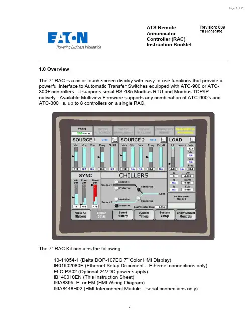
ATS Remote Annunciator Controller (RAC) Instruction BookletRevision: 009 IB140010EN1.0 OverviewThe 7” RAC is a color touch-screen display with easy-to-use functions that provide a powerful interface to Automatic Transfer Switches equipped with ATC-900 or ATC-300+ controllers. It supports serial RS-485 Modbus RTU and Modbus TCP/IPnatively. Available Multiview Firmware supports any combination of ATC-900’s and ATC-300+’s , up to 8 controllers on a single RAC.The 7” RAC Kit contains the following: 10-11054-1 (Delta DOP-107EG 7” Color HMI Display ) IB01602080E (Ethernet Setup Document – Ethernet connections only) ELC-PS02 (Optional 24VDC power supply) IB140010EN (This Instruction Sheet) 66A8395, E, or EM (HMI Wiring Diagram) 66A8448H02 (HMI Interconnect Module –serial connections only)2.0 FeaturesThere are three types of features incorporated into the RAC: Status, Control, and Setpoint Editing.Status Indicators∙S1 / S2 Available∙S1 / S2 Preferred (ATC-900 only)∙S1 / S2 Connected∙S1 / S2 Status∙Emergency Inhibit∙Lockout / Monitor Mode∙Go to Emergency Active∙Engine Test Active∙Transfer in Progress∙Source 1 Voltage Metering∙Source 2 Voltage Metering∙Load Voltage Metering (ATC-900 only)∙Load Current Metering (ATC-900 with DCT module only)∙Waiting for Manual Retransfer∙History of Events∙Active Timers∙Last Transfer Time (ATC-900 only)Controls∙Go to Emergency / Cancel Go to Emergency∙Start / Stop Engine Test∙Alarm Silence∙Remote Alarm Reset∙Bypass Timers∙Manual Retransfer3.0 Setup and WiringThe RAC requires a 24VDC voltage source with a minimum current of 360 mA. There is a removable terminal block connector on the back of the unit for incoming power termination.The RAC supports Modbus RTU (serial RS-485) and Modbus TCP/IP (Ethernet). However, since ATS controllers only support Modbus RTU, an RS-485 serial-to-Ethernet gateway must be used for Modbus TCP/IP. Eaton recommends using the ELC-CAENET module or a Power Xpert Gateway (PXG-900).Drawing 66A8395 shows the wiring of the unit over serial Modbus. Consult drawing 66A8395E (or EM) when using Ethernet gateways. All RS-485 serial cable must have three insulated conductors (D0, D1, COM) and one ground (drain) connected to theshielding of the cable. The Eaton recommended cable is Belden 3106A. Ethernet cable may be any CAT5/6 certified cable.Note: multiple Modbus Ethernet gateways may be used to further expand thecommunication flexibility of the system. Drawing 66A8395EM should be referenced for wiring of multiple gateways. This requires custom firmware per installation site.DOP-107EG Rear ViewELC-CAENET Ethernet Gateway PXG-900 Ethernet Gateway3.1 ATS Controller SetupEvery ATS controller connected to the RAC needs to be set as follows: Modbus Configuration (ATC-900): 9600, 1-stop, NoneBaud Rate (ATC-300+): 9600Address: 01, 02, 03, 04, 05, 06, 07 or 08 (each controller connected to a single RAC must be a unique address)Termination SW1: Normally set to OFF. However, for long communication runs or when experiencing communication timeouts, a 120 Ohm resistor may beinstalled on one end of the communication daisy-chain (see drawing 66A8395 for proper resistor location). If this is done, SW1 must be set to ON only on the last controller in the communication daisy-chain. All other controllers must be set to OFF.3.2 RAC SetupThe firmware comes preloaded onto the unit according to your switch configuration when ordered through your Eaton ATS distributor and should require no user firmware uploading. If your firmware is corrupt or the wrong version was uploaded, please contact ATS Tech Support for assistance.Your RAC is factory set with communications disabled for all controllers and must be enabled during startup. To enable communications, press on any disabled controller from the Overview screen (or the Station Detail screen for Singleview Firmware). Enter your level 2 password (default of AC45). A list of available controller com links will appear. To enable communications to a controller, press the red “Disabled” button under the Coms column; it will change green and display “Enabled”. To disable communications to a controller, press the green “Enabled” button; it will chan ge back red and display “Disabled”. More detail is available in Section 4.5.4.0 RAC ScreensThe RAC has a total of 6 screen types. The following is a summary of the available screens and their function:∙Overview– In a multi-controller system, this shows the status of all controllers at once. This screen will not be shown if you only have a single controllerenabled in the System Setup screen.∙Station Detail– Shows a more detailed view of a single station and gives limited control functionality.∙Trend Data (S1/S2/Load) – Shows trend data (voltage, frequency, unbalance, and load current) for each of the sources and load.∙Alarms and Events– Shows the user a time and date-stamped list of certain events and alarms.∙System Setup– Allows naming, enabling/disabling coms, and setpoint editing of each controller along with password and HMI setup.∙Controller Setpoints – Allows viewing and editing of every available setpoint on the ATS controllers.4.1 Overview ScreenThe Overview screen (Multiview firmware only) shows the status of up to 8 ATS controllers. In the example above, Station 1, an ATC-900 transfer switch named ATS1, has S1 connected, S2 preferred, and no bus energized. Station 2, an ATC-300+ transfer switch named DEMO ROOM, has S1 available and connected. Station 3 has timed out and is trying to reconnect automatically. Station 4, an ATC-900 named CHILLERS, is connected to S2 (non-preferred source) due to a S1 power failure. Stations 5 through 8 are disabled per the user.To view more details and controls for any communicating transfer switch, press anywhere inside the desired station window. This will take you to the Station Detail screen (section 4.2) for that transfer switch.If any controller has an Alarm condition, anaudible alarm will sound from the RAC. To viewthe alarm, press on the station window of thealarmed controller. Once you are on the StationDetail screen, an alarm popup window shouldbe displayed. To silence the alarm, press“Silence Alarm s” button. To perform a remotealarm reset, press the “Remote Alarm Reset”button (only available on ATC-900 controllers).To close the a larm popup, press “Close”.To view the alarm popup window again at any time, press the “ATC -xxx IN ALARM” indicator on the Station Detail screen.4.2 Station Detail ScreenThe Station Detail shows a more detailed view of a single controller. Note: ATC-300+ controllers have no Load monitoring. The top area contains status indicators. Status indicators change from gray to ayellow or red color when active.Below the status indicators are the Source 1, Source 2, and Load detail windows. These windows include graphical and numerical represen-tations of voltage, frequency, and phase loss/unbalance as well as status indication and a trend screen button (Section 4.4). If your controller has a DCT Module add-on, you will see additional Load metering including kilowatts,kVAR, kVA, power-factor, and three-phase current.The voltage, frequency, phase-loss, and unbalance indicators have been designed to show aquick graphical representation of how ‘healthy’ the source is. The top grey area indicates the Over-voltage or frequency dropoutrange. The bottom grey area indicates the Under-voltage or frequency dropout range. The middle light-blue area indicatesthe “good” range. These areas resize dynamically depending on how the dropouts are set in the controller setpoints. If the voltage or frequency reaches the upper or lower ranges, they will turn from grey to red, indicating a problem. Note that the numerical value will change to “N/A” if the va lue is ever invalid (e.g. Vbc, Vca, and Unbalance in a single-phase system.)Below the Source 1, Source 2, and Load status windows is the Source Sync window. On three-phase systems, this window will display how far apart the two power sources are from each other. The difference is given in Volts, Frequency, and Phase. When closed transition or in-phase is enabled, the allowable range will be shown on the bar graph. If the difference is higher than the allowable range, it will turn from grey to red, indicating that it is not okay to do an in-phase or closed transition at that time.Note that there are different indicators for closed (CT) and in-phase (IP) transitions for Frequency and Phase Difference. ATC-300+ only supports in-phase transitions.To the left of the Source Sync window is the Mimic Bus window. This window acts identically to the mimic bus onthe System Overview screen.The upper banner displays thename of the selected controller. The bus area shows which source is available, preferred,and connected. Active lights are white, while inactive lights are black. The currently energizedbus is depicted by a light-bluecolored line.To the right of the Mimic Bus area is the Manual Retransfer window. This area indicates whether manual retransfer isenabled or disabled, as well as alertingthe user if the transfer switch controller is waiting for a manual retransfer signal. The manual retransfer can be initiated remotely by pressing the button labeled “Press to Retransfer” when it appears on the RAC (password protected, level 1).The bottom area of the screen shows navigation and control buttons. The “View all Stations” button navigates to the Overview Screen (Section 4.1). Note: this button is not available if only a single station is enabled. The “Event History” button navigates to the Alarm/Events Summary screen (Section 4.3). The “System Setup” button navigates to the System Setup screen (Section 4.4).Show/Hide Manual Controls: This button expands a small window with 3 control buttons: Go to Emergency, Bypass Timers, and Start Engine Test. All control is password protected level 1. To hide the manual controls, press the “Hide Manual Controls” button.Start Engine Test/Cancel Engine Test: To initiate an engine test remotely from the RAC, press the Start Engine Test button and enter your level 1 password. The controller will close its generator start contacts. Once the generator has reached nominal voltage, the test will run until the Engine Test Run Time expires. If your controller is programmed for a Load Transfer test, then it will also transfer your load to the generator during the test. To abort the test early, push the Cancel Engine Test button on the RAC.Go to Emergency/Cancel Go to Emergency: This button sends the controller a remote Go to Emergency command (password protected, level 1). Once initiated, the controller will transfer to your non-preferred (emergency) source. To go back to your preferred (normal) source, push the Cancel Go to Emergency button.Bypass Timers: Allows the user to skip a currently active timer. While a valid timer is counting down, simply press the button, enter the level 1 password, and it will be bypassed. This button works for the following timers:4.3 Alarm and Events ScreenControllerEventsControllerAlarmsThe Alarm and Events screen displays time/date-stamped alarms (in red) and events (in black) for all connected controllers. This information is s tored in the HMI’s memory, and will not be erased if the unit is powered down. Therefore, a “Reset History” pushbutton is provided to clear all historical events and alarms if needed. A list of all available messages is shown below:4.4 Trend ScreensTrendLabelOverfreq.RangeUnderfreq.RangeNavigationSlidersCurrentData PenThe Trend screens show a graphical representation of Voltage, Frequency, Unbalance, and Amperage (Load trend only). The HMI takes data samples every 1 second for each controller it communicates to. The internal storage of the HMI can store up to 8.6 hours of historical data. The HMI can be configured from the factory to export and store additional data on an external USB drive or SD card. Additionally, data saved to external devices can be viewed on any PC program that supports CSV files.If applicable, the trend windows also display the Under/Over-Frequency, Voltage, and Unbalance limits as set in the ATC-900. These are depicted by the red horizontal lines on each trend window.To view trend data on the HMI, simply press the Trend button of the voltage source you wish to view (Source 1, Source 2, or Load). Once on the trend screen, you can go back and forth through time by using the scroll bar and arrows on the bottom of each trend window. The most recent data is on the right side of the trend window, while the oldest data is on the left side. To see a data point value at a specific point in time, press on the screen at the desired point and the HMI will draw a vertical line there and display the data value.4.5 System Setup ScreenStation Name: The RAC allows the user to name each ATS controller (up to 8 controllers per RAC with Multiview Firmware). Simply press the Edit button next to the controller you wish to name and type in your desired name using the on-screen keyboard.Coms: The user can also enable/disable any communication link between the RAC and controller by pressing on the Enabled/Disabled button next to the corresponding controller. When enabled, the display will show a green “Enabled” button; when disabled, the display will show a red “Disabled” button. To toggle the communication state, simply press the button and the state will toggle.Coms Status: The RAC will display the current status for all 8 stations. Possible coms statuses are:∙Off – Coms are Disabled∙Trying to Connect – Coms are enabled but have not been established yet.∙Timed Out – Coms have been established but are now not responding.∙Good – Coms have been established and no issues are detected.Type/FW Ver.: When Coms are enabled for the first time, the RAC will automatically poll the controller to see what type it is (ATC-300+ or ATC-900), as well as read the controller’s firmware v ersion. The type and FW version for each station can be seen on the far-right of the System Setup screen.HMI Setup (Admin Level): This button opens a menu that allows the operator to change items like touch screen force, touch screen calibration, time & date, brightness & contrast, alarm & touch volume, and others. By default, the HMI should be set up so the user will not have to adjust anything in the field. Specific details on each setting can be found in the Delta HMI Manual.Password Setup (Admin Level): As mentioned earlier, passwords are needed to initiate controller functions and to access the setup menus. If you would like to change the passwords, press the Password Setup button in the Controller Setup screen.The operator level applies to operator-related actions, such as initiating an engine test or go to emergency command, enabling/disabling controllers, and naming controllers. Admin level allows changing controller setpoints, changing of HMI setup, and editing passwords.Caution: if you change your passwords, do not forget them or you will beunable to access these features!4.6 Controller SetpointsThe RAC allows the user to program all controller setpoints remotely. The setpoints are organized into categories:∙ System Setup ∙ Time Delays∙ Dropouts & Pickups∙ Engine Test & Plant Exercisers ∙ Programmable I/O (ATC-900 only)To access the desired category, press one of the navigation buttons near the bottom of the screen. The currently active category will turn blue with white text. Somesetpoint categories have more than one page. If this is the case, you will see a “Next Page” button in the upper -right corner. Pressing this will take you to the next setpoint page in that category. The example above shows the System Setup (1 of 3).Pressing the “Next Page” button will take you to System Setup (2 of 3). Pressing the “Previous Page” button will take you back to the previous setpoint screen. Some intermediate pages may have a next and previous page button.Valid Setpoint RangesTo change a setpoint, simply press the corresponding setpoint box (white rectangle with blue border) and you will be prompted to enter a new setpoint value. Valid setpoint entries are always shown to the right of the setpoint box. For example, the CT Ratio (x : 5) setpoint can be set to 0 (none), or anywhere between 200 and 5000. If you are outside the limits, the RAC will display a popup letting you know it was an invalid entry.To return to the Controller Setup menu at any time, press the “Return to Controller Setup” button in the upper-left corner.For more information on any setpoint, consult the appropriate controller IB.CAUTIONThis is a remote-control device. Caution should be applied to make sure that appropriate procedures are in place for Engine Tests and Remote Transfers. Appropriate procedures include, but are not limited to, switch doors being closed and latched, personnel knowledgeable of transfers, and other site safety recommended procedures.。
GE MX150 & MX250 控制器设定指南
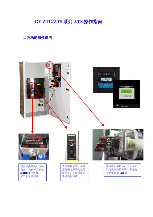
GE ZTG/ZTS 系列ATS 操作指南1. 各功能部件说明2.MX150/MX250开机设置1) 显示电压校准将两路电源通电,如果备用侧为发电机,须手动启动发电机,将发电机电源送至ATS 备用侧(也可用临时电源进行测试),当两路电源均有电,ATS 在常用侧时,ATS 的LED 指示应如下所示:第1、2、4个LED 灯亮:如果没进行显示电压校准,即使两路电源有电,可能S1电源指示灯(第1个LED )和S2电源指示灯(第4个LED )灯不亮,所以ATS 可能不转换:a) 请按照如下程序校准S1显示电压:控制器初始界面两路电源线电压,应该是380V,如果电压偏差很大,按SET 进入设置界面按MORE 一直看到左边界面输入密码121212,按SAVE 键在中国应该显示: 380 =N1 TO N3, 如果不是, 用2&3键进行修改,然后按SAVE 保存b) 用同样的方法对S2发电机电压进行校准2) 时间延时调整面是各个时间参数的设置界面及默认值下N转换到E延时:1秒发电机启动延时,默认值3秒仅限于延时转换型,N转换到E仅限于延时转换型,E转换到N 时停留在中间位置延时:5秒时停留在中间位置延时:5秒E转换至N延时:30分钟发动机冷却延时:5分钟下面以修改备用侧回切至常用侧延时(设定为5秒)为例说明如何修改延时:控制器初始界面MORE按按SET 进入设置界面SEL 按键输入密码: 121212,按SAVE 键光标首先会停留在分钟的位置,通国2&3键将分钟位置设为00,按SAVE 保存;光标将切换至秒位置,通过2&3键将秒位置设为05秒,按SAVE 保存按MORE 键一直看到右下键出现BACK,按BACK 键可回到上级菜单。
7000系列ATS(30A-230A)操作手册
接线
电缆隔片 38mm 间隙
随 ASCO 7000 系列 ATS 附有一份接线图 (不在本手册中)。参见该图。所有接线必须
电缆隔片
遵从美国国家电气规程和当地规定。
危险
进行任何接线或辅助电路连接前,应断开导
图 1-1:150A、200A、230A 自动转换开关的电缆隔片
负载电 源连接
备用电源连接
维护手柄(见操 作手册警告)
引擎启动 端子
常用电源连接
电缆隔离片 (见安装)
转换控制 及指示灯
控制器
典型的 150 安带外箱 ATS
1、安 装
ASCO 7000 系列自动转换开关(ATS)出厂 前已完成接线及测试。现场安装需要组装、连 接电缆及连接油机起动和辅助控制电路(如有 需求)。
转换测试
3
本程序中,常用及备用供电电源须可用, 且紧急供电引擎(如使用)须能启动。
执行右边第 1 – 5 步。观察状态灯。
4
● 黑色块表示灯亮 ○ 白色块表示灯灭
5
顺时针转动及按住转换控 制开关进行转换测试,直到 引擎启动及运行(15 秒内)。 被备用电源有效侧指示灯 应点亮。
在 2B 时延后,转换开关将 在转换至备用电源侧。负载 使用备用电源指示灯应点 亮而负载使用常用电源指 示灯应熄灭。
2、测试与维护
转换开关测试
断开控制器
每月至少按以下第 1-4 的电气操作转换 测试步骤(含五个步骤)运行一次 7000 系列 ATS。
预防性维护
预防性维护过程中的适度小心可确保 7000 系列 ATS 的高可靠性及长使用寿命。建 议每年进行一次预防性维护项目。
HAT520 ATS控制器用户手册说明书
HAT520 ATS CONTROLLER USER MANUALSmartgen TechnologyChinese trademarkEnglish trademarkSmartgen— make your generator smartSmartgen Technology Co., Ltd.No. 28 Jinsuo RoadZhengzhou CityHenan ProvinceP. R. ChinaTel: +86-371-67988888+86-371-67981888+86-371-67991553+86-371-67992951+86-371-67981000(overseas)Fax: 0086-371-67992952Web://Email:*****************All rights reserved. No part of this publication may be reproduced in any material form (including photocopying or storing in any medium by electronic means or other) without the written permission of the copyright holder.Smartgen Technology reserves the right to change the contents of this document without prior notice.If colors of actual products are different from those mentioned within this manual, please take the actual product as the standard.Software VersionClarification of notation used within this publication.NOTECONTENT1OVERVIEW (5)2PERFORMANCE AND CHARACTERISTICS (6)3SPECIFICATION (8)4PANEL DESCRIPTION (9)5PANEL BUTTON OPERATION (10)5.1PRIORITY SETTING (11)5.2AC SYSTEM SETTING (12)5.3DELAY ADJUSTMENT (13)5.4RESTORE FACTORY DEFAULT (14)6PROGRAMMED PARAMETER AND RANGE (15)7OPERATION CONTROL (17)8DESCRIPTION OF CONNECTING TERMINALS (18)9TYPICAL WIRING DIAGRAM (19)10INSTALLATION (21)11FAULT FINDING (22)1 OVERVIEWThe powerful Microprocessor contained within the HAT520ATS controller allows for precision voltage (2-way 3-phase/single phase) measuring and make accurate judgment on abnormal voltage (power lost, over/under voltage, over/under frequency, loss of phase, phase sequence wrong) and control ATS to transfer after the delay has expired. This controller is suitable for NO Breaking ATS. When 1# power is abnormal, the controller will send signal to start genset after the “1# abnormal delay”has expired. “Three remote”(remote control, remote measurement and remote communication) function can be implemented with the help of LINK communication port.2 PERFORMANCE AND CHARACTERISTICSHAT520ATS controller can monitor 2-way 3-phase 4-wire voltage, 2-phase 3-wire and single-phase 2-wire voltage (2 way mains, or 1 way mains and 1 way generator) and control ATS to transfer. Its performance and characteristics are shown as below,◙Measure and display 2-way 3 phase Voltage and Frequency:1# 2#Line voltage (Uab, Ubc, Uca) Line voltage (Uab, Ubc, Uca)Phase voltage (Ua, Ub, Uc) Phase voltage (Ua, Ub, Uc)Frequency Hz Frequency Hz◙Over/under voltage, loss of phase, phase sequence wrong, over/under frequency protection function. As default, phase sequence wrong protection and over/under frequency protection are disable; however, users can set the protection function as need.◙Parameters can be set via PC software using SG72 module (USB to LINK) or other converse module.◙The voltage normal delay of 1# or 2#can be set in (0~60) seconds and the Genset start delay can be set in (0~3600) seconds.◙The voltage abnormal delay of 1# or 2#can be set in (0~60) seconds and the Genset stop delay can be set in (0~3600) seconds.◙“1# power priority”, “Auto/Manual”, “No priority” and “2#power priority” can be set via controller front panel.◙Closing output signal can be set as on intervals or as continuous output.◙Applicable for 2 isolated neutral line.◙Auto/Manual mode. In manual mode, ATS transfer can be implemented via panel pushbutton.◙LEDs mounted on front panel can clearly show ATS running status.◙The output contactor capacity of 1# and 2#power supply transfer relay (1#CLOSE, 2#CLOSE) is 16A AC250V, volts-free contact, can be directly used in driving switch to transfer.◙The output contactor capacity of Genset start relay (GENS START) is 7A AC250V/7A DC28V, volts-free N/C contact.◙Suitable for various AC systems (3 phase 4-wires, 2-phase 3-wires and single-phase 2-wire).◙Controller has strong ability of anti-electromagnetic interference, can be used undercomplex electromagnetic interference environment.◙Modular design, self extinguishing ABS plastic shell, pluggable terminal, built-in mounting,compact structure with easy installation.3 SPECIFICATION4 PANEL DESCRIPTIONNOTE: indicators description:1. Indicators Description (in test mode):1# Power Indicator:It is illuminated when 1# power is normal; flashing when 1# power state is abnormal; off when there is no 1# power.2# Power Indicator:It is illuminated when 2# power is normal; flashing when 2# power state is abnormal; off when there is no 2# power.1# Close Indicator:It is illuminated when 1# power auxiliary contactor is active while off when it is deactivated.2# Close Indicator:It is illuminated when 2# power auxiliary contactor is active while off when it is deactivated.Auto Mode Indicator: It is illuminated when the controller is in auto mode while off the controller is in manual mode.Manual Mode Indicator: It is illuminated when the controller is in manual mode while off the controller is in auto mode.2. Indicators Description (When set the parameters)More details please refer to the following description of “Panel Button Operation”5 PANEL BUTTON OPERATIONPressing and holding the button for more than 3s, all LEDs are illuminated to enter into lamp test mode; under this mode, the controller will back to normal status automatically after release the button.Pressing and holding the button for more than 7s, all LEDs are flashing (500ms per time) to enter into parameter setting status, users can set the parameters after release the button. If users don’t want to set the parameters under this status: 1) Pressing and holding the button again until all LEDs are flashing 5 times rapidly (200ms per time) which means the controller enter into normal status; 2) Or the controller will back to normal status automatically about 90s later.5.1 P RIORITY SETTINGPower priority can be set only when the controller is in parameters setting status. Procedures of setting “1# power priority”, “2#power priority” and “No priority”:1) Press,andat the same time, when 1#/2#power indicator and auto indicatorare illuminated; release the three buttons, then the auto indicator and 2#power indicators extinguish, 1# power indicator illuminates, which means controller priority can be set. 2) Pressingcan circularly set 3 priority conditions of power supply.1# Power Priority: 1# power indicator illuminates and 2#power indicator extinguishes ;2#Power Priority: 2#power indicator illuminates and 1# power indicator extinguishes ; No Priority: 1# power and 2#power indicators are illuminating at the same time; 3) After adjusting, press, when 1# power indicator, auto indicator and 2#power indicatorare illuminating, the adjusted power priority has been saved. The controller will back to normal status automatically after all LEDs are flashing 5 times rapidly and controller will work according to the priority.Note: Once the controller is power on, its priority can be judged by the following three conditions.I f 1# power supply indicator flashes rapidly for three times, indicating 1# power supply for priority transfer.I f 2#power supply indicator flashes rapidly for three times, indicating 2#power supply for priority transfer.I f 1# and 2#power supply indicators flash simultaneously for three times, indicating there is no priority transfer.5.2 A C SYSTEM SETTINGAC system can be set only when the controller is in parameters setting status.Procedures of setting “Single-phase 2-wire”,“3-phase 4-wire” and “2-phase 3-wire”:1) Press, and at the same time, when 1#/2#power indicator and auto indicatorare illuminated; release the three buttons, then the auto indicator and 2#power indicators extinguish, 1# power indicator illuminates.2) Press , when 1#/2#power indicator and auto indicator are illuminated; release thebutton, then the auto indicator and 1#/2#power indicators are extinguished simultaneously, which means controller AC system can be set.3) Pressing can circularly set three AC systems.Single-phase 2-wire: 1# close indicator illuminates;3-phase 4-wire: 1# close indicator, 2#close indicator and manual mode indicator illuminates simultaneously;2-phase 3-wire: 1# close indicator and manual mode indicator illuminates simultaneously;4) After adjusting, press, when 1# power indicator, auto indicator and 2#powerindicator are illuminating, the adjusted AC system has been saved. The controller will back to normal status automatically after all LEDs are flashing 5 times rapidly and controller will work according to the set AC system.Note: Once the controller is power on, its AC system can be judged by the following three conditions.I f 1# close indicator illuminates means Single-phase 2-wire system is selected.I f 1# close indicator, manual mode indicator and 2#close indicator illuminatesimultaneously means 3-phase 4-wire system is selected.If 1# close indicator and manual mode indicator illuminate simultaneously means 2-phase 3-wire system is selected.5.3 D ELAY ADJUSTMENTDelay value can be set only when the controller is in parameters setting status.♦Adjusting “1# power normal delay” potentiometer (locate nearby the back panel terminal) can set output delay after 1# power supply is normal.♦Adjusting “2#power normal delay” potentiometer (locate nearby the back panel terminal) can set output delay after 2#power supply is normal.Setting Procedures of “1# power abnormal delay” and “2#power abnormal delay”:a) Press and at the same time, when 1#/2#power indicator and auto indicator areilluminated; release the two buttons, then the auto indicator and 1#/2#power indicators are extinguished simultaneously which means the delay timer of the controller can be set.1# power abnormal delay: adjust “1# Power Normal Delay” potentiometer;2#power abnormal delay: adjust “2#Power Normal Delay” potentiometer;b) After adjusting the delays, press. When 1#/2#power indicator and automaticindicator are illuminated simultaneously, the adjusted value has been saved. The controller will back to normal status automatically after all LEDs are flashing 5 times rapidly and controller will work according to the set delay values.NOTE:1# Normal Delay set value must be no less than 1# Abnormal Delay, otherwise, 1# Normal Delay set value will be forced set as 1# Abnormal Delay set value.The matters need attention of 2# is same as 1#.5.4 R ESTORE FACTORY DEFAULTDefault value can be set only when the controller is in parameters setting status.a) Press and at the same time, when 1#/2#power indicator and auto indicator areilluminated; release the two buttons, then the auto indicator and 1#/2#power indicators are extinguished simultaneously which means the default delay value of the controller can be set.b) Press, when 1#/2#power indicator and auto indicator are illuminated simultaneously,the factory default has been restored. The controller will back to normal status automatically after all LEDs are flashing 5 times rapidly and controller will work according to the set delay values.Note: By default, 1# and 2#abnormal delay is 5s and genset stop delay is 90s.6 PROGRAMMED PARAMETER AND RANGE“1#If motor driving type ATS (e.g. SOCOMEC VS) is applied, the Close delay and Open delay must be no less than 5s; If magnet driving type ATS (e.g. SGQ-N) is applied, the Exceed Transfer delay must be set as 0.7 OPERATION CONTROLAuto/Manual Operation:When controller is running, pressing key can set the controller as Auto mode orManual mode (indicate by automatic and manual indicators). In Manual mode, presskey, load will be transferred to 1# power supply; press key, load will be transferred to 2#power supply.8 DESCRIPTION OF CONNECTING TERMINALS9 TYPICAL WIRING DIAGRAMSGQ-N/T Wiring DiagramSGQ-M Wiring DiagramNote:The diagram is for reference only. The actual wiring shall follow the ATS instruction. Users should choose proper fuse capacity according to the actual power consumption.2-phase 3-wire Wiring DiagramSingle phase 2-wire Wiring DiagramNOTE:Above pictures take the AC 220V voltage as example. If AC 110V voltage is applied in actual use, please contact with Smartgen technical staff to get the specific wiring methods.10 I NSTALLATION11 F AULT FINDING。
施耐德atsD型控制器用户手册修订稿
施耐德a t s D型控制器用户手册WEIHUA system office room 【WEIHUA 16H-WEIHUA WEIHUA8Q8-D型控制器用户手册●●●●施耐德万高(天津)电气设备有限公司Schneider Wingoal (Tianjin) Electric Equipment Co., Ltd下面的符号将用于本手册的说明,提醒您注意潜在的危险,或者请您注意那些阐述、简化过程和关键操作。
身安全危险或本开关的不可恢复性损坏。
: 关键性操作,提示您使用不当时,可能使控制器工作于非正常状态。
:提供另外的信息或简化的操作方法。
请注意:电气设备应该让有资格的专业人员进行安装、操作、使用、维护。
未按使用手册操作而造成的不良后果,施耐德电气公司将不负任何责任。
控制器功能介绍本控制器工作电压为AC380V,工作频率为50Hz,主要功能是进行电压采集,根据电压的实时值进行故障判断(三相断相、欠压、过压和失压),并控制转换开关进行相应的转换动作。
用户还可根据实际需要选配电流模块实现实时电流、有功功率和有功电能的显示。
另外,控制器提供多组无源节点的输入和输出,包括故障输出、负荷卸载、发电机启动、动作无源输出、远程投备(无源输入)、消防联动(无源输入)以及通讯接口,具体接线参见第节。
控制器安装及接线说明1.1.控制器外形尺寸图1 D型控制器外形尺寸1.2. 控制器二次接线1.2.1. 控制器端子说明1.2.2. A1-A3备A4-D2,A5-RJ,A6-OUT,A7-D3,A8-D1,A9-NJ,A10-12,主 A2A3A4A5A6A7A8A9A10A11A12OUTB1B2B3B4B5B6B7B8B9B10B11B12故障输出负荷卸载主转备备转主发电机启动C1C2C3C4C5C6C7C8C9C10空D3NBRB空远程投备消防联动D1D2D3D4D5D6D7D8D9D10D11D12ABA`B`G空IC*IB*IA*动作输出RS485IC IBIA☐动作输出:当机构中电机转动时,常开触点闭合; ☐ 故障输出:当常用或备用电源故障时,常开触点闭合;☐ 负荷卸载:在电网-发电机模式下,常用电源故障,常开触点闭合;☐发电机启动:在电网-发电机模式下,常用电源正常,常开触点闭合,常用电源故障,常开触点打开;☐ RS485:通信用端口,A’ B’为通信预留端口;☐ IA~IC :电流互感器输入端口I*为输入端,I 为输出端;(输入额定电流5A ) ☐ 远程投备(无源):短接此两点,机构转到备用位置,开关状态主分备合;(可靠距离10m)☐ 消防联动(无源):短接此两点,机构转到双分位置,开关状态主分备分;(可靠距离10m,WTS-D800~5000系列不具备该项功能): 控制器的发电机启动端子在常用电源正常时常闭触点断开,当常用电源故障时常闭触点闭合以接通发电机启动电路;常开触点与之相反,请用户注意。
ATS021双电源控制器说明书
ATS021符合以下标准: 欧洲指令 73/23“LVD-低压指示” EN-IEC 50178:电力安装的电子设备使用 EN-IEC 62103:电力安装的电子设备使用 EN-IEC 60947-5-1:低压开关和控制设备:控制电路电器和开关元件-机电式控制电路电器 电磁兼容:EN50081-2,EN50082-2 环境条件:IEC 68-2-1,IEC68-2-2和IEC 68-2-3 EN-IEC 61000-4-2:电磁兼容-第4-2部分:试验和测量技术 静电放电抗扰度试验(8KV 空气放电,4KV 接触放电) EN-IEC 61000-4-3:电磁兼容-第4-3部分:试验和测量技术:射频电磁场辐射抗扰度试验(等级3) EN-IEC 61000-4-4:电磁兼容-第4-4部分:试验和测量技术:电快速瞬变脉冲群抗扰度试验(等级2/3) EN-IEC 61000-4-5:电磁兼容-第4-5部分:试验和测量技术:浪涌(冲击)抗扰度试验(等级1/2) EN-IEC 61000-4-6:电磁兼容-第4-6部分:试验和测量技术:射频场感应的传导骚扰抗扰度(等级3)
使用自动控制单元ATS021 ............................................. 29
外观 ............................................................................. 29 配置 ............................................................................. 29 旋钮开关 ......................................................................... 29 按钮键盘 ......................................................................... 30 LEDs ............................................................................. 31 外部变压器 ....................................................................... 32 测试次序 ......................................................................... 33