
宝马内部培训材料
1981年 第二代5er
奥迪VS宝马 对比分析培训
BMW5系车型历史
第三代BMW 5系是一款全新的车型。发动机系列中包括4缸、6缸、8 缸发动机。1997年秋季,带有数字式柴油喷射系统、增压空气冷却装置、 三元催化转换器的全新2.5升涡轮增压柴油发动机也被列入了选择装备的 范围。
1988年 第三代5er
奥迪VS宝马 对比分析培训
BMW5系车型历史
第二代5系拥有非常精美的车身外观设计、更好的流线型、更强的安全性、更高的驾 驶舒适性。此外,发动机范围也达到了前所未有的丰富:4缸和6缸汽油发动机、525e车 型上为实现最大燃油经济性而设计的发动机、M5车型上的24气门顶置凸轮轴动力单元, 以及带有涡轮增压器和不带涡轮增压器的6缸柴油发动机。5档变速箱从1983年起成为5系 的标准装备(之前为选择装备),并且提供4档自动变速箱供客户选择
奥迪VS宝马 对比分析培训
奥迪VS宝马 对比分析培训
奥迪VS宝马 对比分析培训
奥迪VS宝马 对比分析培训
奥迪VS宝马 对比分析培训
奥迪VS宝马 对比分析培训
奥迪VS宝马 对比分析培训
——5系Li车型比原5系后排加长140mm,轴距 达到3028mm。 ——挑高车顶,下沉坐椅。
奥迪VS宝马 对比分析培训
——前部铝制材料,后部采用高强度钢材,平衡车身的比重。
奥迪VS宝马 对比分析训
奥迪VS宝马 对比分析培训
关注:
——鹰眼大灯、转向灯
——车身棱角线条 ——双肾进气隔删
奥迪VS宝马 对比分析培训
奥迪VS宝马 对比分析培训
奥迪VS宝马 对比分析培训
奥迪VS宝马 对比分析培训
奥迪VS宝马 对比分析培训
宝马5系VS奥迪A6L2.4CVT
——BMW 运动与锐利 ——AUDI 内敛和含蓄
奥迪VS宝马 对比分析培训
大家谈谈目前印象中的宝马?
奥迪VS宝马 对比分析培训
宝马汽车公司简史
与Mercedes Benz、Rolls Royce等老牌车厂相比,宝马则年轻很多。它成立 于1916年,公司总部在德国慕尼黑,名称为巴伐利亚发动机厂( Bavarian Motor Works )。公司产品是一款直列六缸发动机,在第一次世界大战时装配在德国空 军的战斗机上。 宝马公司的车标是蓝白相间图案,蓝色代表蓝天,白色 代表白云,整体造型意味着旋转不停的螺旋浆,这个创意来 源于宝马公司曾经制造飞机发动机的传统。 1922年,宝马公司开始生产摩托车R-32,采用500ml风 冷水平对置两汽缸发动机,动力通过传动轴而不是链条传递 到后轮,为宝马摩托车定下了样本。
奥迪VS宝马 对比分析培训
典雅型 472600 BMW 5系 BMW 523Li 领先型 486600 豪华型 521600
典雅型 563600 BMW 525Li 豪华型625600
典雅型608600 BMW 530Li 领先型646600 豪华型712600
奥迪VS宝马 对比分析培训
BMW 5系外观
奥迪VS宝马 对比分析培训
基本参数 车型名称: 报价: 品牌: 级别: 发动机: 变速箱: 长×宽×高: 车体结构: 车身 长度: 宽度: 高度: 车重: 轴距: 前轮距: 后轮距: 最小离地间隙: 车身结构: 车门数: 座位数: 油箱容积: 行李箱容积: 1595 3028 1558 1582 三厢车 4 5 70 520 80 501 142 1775 (+180) 2945 (-83) 宝马5系 523Li豪华型 宝马5系 523Li豪华型 52.16万 华晨宝马 中大型车 2.5L 177马力 L6 6挡手自一体 4981×1846×1477 4门5座三厢车 宝马5系 523Li豪华型 4981 1846 1477 5012 (+31) 1855 (+9) 1485 (+8) 2.4L 177马力 V6 7档无级/手动一体 5012*1855-1485 52.61万 一汽奥迪 奥迪A6L2.4CVT尊享型
奥迪VS宝马 对比分析培训
奥迪VS宝马 对比分析培训
奥迪VS宝马 对比分析培训
奥迪VS宝马 对比分析培训
BMW车系 BMW 3系 BMW 5系 BMW 7系 BMW X3 BMW X5 BMW Z4 BMW M6 BMW MINI
AUDI车系 AUDI A4 AUDI A6L AUDI A8L
奥迪VS宝马 对比分析培训
BMW5系车型历史
作为BMW 1500-2000“新级别”车型的直接后继车型,BMW 5系四门中 型轿车于1972年面世。由于慕尼黑工厂的生产力已经不足以满足预计的产量 要求,BMW在下巴伐利亚的Dingolfing建造了一座采用全新专门设计的工厂。
1972年 第一代5er
奥迪VS宝马 对比分析培训
白杨木板内饰
奥迪VS宝马 对比分析培训
奥迪VS宝马 对比分析培训
——7英寸显示屏幕 ——通讯、气候控制、导航、娱乐4个功能 ——但MENU键只能直接返回首页面,操作不方便
——简单明了的内饰风格 仍然采用手制动拉杆
奥迪VS宝马 对比分析培训
奥迪VS宝马 对比分析培训
宝马公司总部
奥迪VS宝马 对比分析培训
品牌/车型简介
Vorsprung durch Technik
Sheer driving pleasure
突破科技,启迪未来
驾驶乐趣
奥迪VS宝马 对比分析培训
宝马品牌
驾驶乐趣 Sheer driving pleasure
Joy 快乐 Dynamic 动感 Cultured 素养 Challenging 挑战
4
177
最大功率(kW):
最大功率转速: 最大扭矩(N· m): 最大扭矩转速(rpm): 发动机特有技术: 燃油: 燃油标号: 供油方式: 缸体材料: 缸盖材料: 环保标准:
130
5800 230 3500-5000 Double VANOS/Valvetronic 汽油 97号 多点电喷 铝镁合金 铝镁合金 欧IV
奥迪VS宝马 对比分析培训
BMW5系车型历史
第四代5系的车身外观设计保留了BMW特有的传统造型元素。由于外部尺寸更大,第 四代5系拥有更宽敞的内部空间。在重量没有变化的情况下,白车身采用的轻质结构使其 刚度提高了50%。发动机和悬架也在铝合金材料的广泛使用方面建立了新的标准。5系最 初上市时仅有6缸发动机车型,1996年增加了8缸发动机车型。通过推出540i防弹车, BMW开始将客户对更高人身安全性的需求纳入了车辆设计的考虑范围。这款防弹型轿车 采用直接定制的方式进行生产,车上装备的芳香尼龙纤维和防弹玻璃能够为车内乘员提供 更可靠的人身保护。
62.56万 60.68万 64.66万 2.5L 218马 2.8L 280马 3.0L 258马力 L6 力 L6 力 V6 7档手动/无 6挡手自一体 6挡手自一体 级一体 65.57万 3.2FSI 330马力 V6 6挡手自一体Tip
1500系列非常成功,在这一基础上陆续推出了不同的车型;以满足市场的需 求。上个世纪60、70年代,宝马公司得到了飞速的发展。
奥迪VS宝马 对比分析培训
宝马汽车公司简史
宝马于1994年收购了英国的罗孚集团,包括名下的罗 孚、陆虎、MINI以及MG等品牌(2000年,宝马决定将罗 孚和MG两家工厂以10英磅的象征性价格出售给英国凤凰 集团;陆虎不久也被出售给美国福特公司),BMW保留 了MINI品牌,并获得了巨大的成功。 目前宝马生产3系、5系、6系、7系、X3、X5、Z4和 M系列车型,是世界上最成功的高档轿车品牌之一。
AUDI Q7 AUDI TT AUDI A5
奥迪VS宝马 对比分析培训
BMW 5系 目标客户群总体特点
新宝马5系把目标人群锁定在注重驾驶乐趣与乘车舒适性的社会成功人士, 推出加长轴矩的车型,也就是想对中国行政公务车市场发起冲击,因为之前购 买宝马多是一些事业有成的企业家,较少的公务用户会考虑宝马车款, BMW的全球客户定位:成功的专业人士 评价:在中国宝马的困惑:车越好,车主素质越差
130
6000 230 3000-5000
机油容量:
-
奥迪VS宝马 对比分析培训
宝马5系 奥迪A6L2.4舒 基本参数 523Li 领先型 适型
报价: 48.66万 46.88万 2.4L 177马力 7档手动/无级一体 发动机: 2.5L 177马力 L6 变速箱: 6挡手自一体
差异
1.78万
宝马5系 奥迪 宝马5系 奥迪A6L3.2尊 525Li 豪 A6L2.8FS 530Li 领先 享型 华型 I尊享型 型
奥迪VS宝马 对比分析培训
发动机 排量(cc): 排量(L): 工作方式: 气缸排列型式: 汽缸数: 宝马5系 523Li豪华型 2497 2.5 自然吸气 L 6 V6 6 奥迪A6L2.4尊享型 2393 2.4L
每缸气门数:
压缩比: 气门结构: 缸径: 冲程: 马力:
4
11 DOHC 78.8 82 177
1995年 第四代5er
奥迪VS宝马 对比分析培训
BMW5系车型历史
第五代BMW 5系于2003年5月发布,它在行驶动态特性、性能、效率、舒适性、空间 诸多因素的综合与统一方面,达到了同级车型中前所未有的高度,进而建立了新的标准。 全新5系采用了全球首创的主动转向系统、铝材料和钢材料相结合的车身、全铝底盘、高 性能且高效率的汽油和柴油发,动机、6档变速箱、iDrive控制概念及其它非凡的创新特色, 就任何方面而言都具有出类拔萃的产品品质,从外部设计来看,新BMW 5系Li最显著的特 征是轴距增加了14厘米,为后排乘客提供了特别的舒适感,以及空间感所带来的乘坐乐趣。
Audi A6L主要装备
8喇叭以上扬声器系统 大灯高度可调及大灯清洗装置(选装,2.4以上 车型标配) 泊车辅助系统(2.0T选装,其余车型标配) 升降(空气)悬挂系统(选装,3.2及4.2标配 ) GPS导航(选装) DVD语音电子导航(2.4尊贵型以上车型) 车内空气调节(2.4舒适型以上车型) 车载电话,电动座椅记忆及后视镜电动折叠(选 装,3.2及4.2标配) 车载电视,方向盘换档,后坐出风口及温度分 区控制(2.4技术领先型以上车型) 定速巡航,真皮座椅(2.4以上车型标配)
宝马E65教材培训资料s(11)

69
- Overview
70
- Functional description
73
- Oxygen sensor regulation
74
- Emission control
75
- Oil level/condition
77
- Variable intake manifold
80
- Valvetronic
81
- Idle speed control
83
CHAP 4 N62 fuel system
84
Mixture control
84
- General information
84
- Injection valves
84
- Fuel pressure regulator
85
- Electric fuel pump (EKP)
CHAP 1
InValvetronic principle Introduction of the N62 engine - Technical data - Full load graphs - N62B36 engine view
CHAP 2
Engine mechanics General air intake system Air ducts - Fresh air system - Throttle valve - Variable intake pipe - Crankcase venting system Exhaust system - Exhaust manifold with catalytic converter - Silencer - Secondary air system Auxiliary components and belt drive - Belt drive - Alternator - Coolant compressor - Starter motor - Power steering pump Cylinder heads - Introduction - Cylinder head covers - Valve gear Bi-VANOS (variable camshaft adjustment) - VANOS function - Timing diagram Valvetronic - Description of the function - Valve lift adjustment components - Valvetronic adjustment diagram - Chain drive
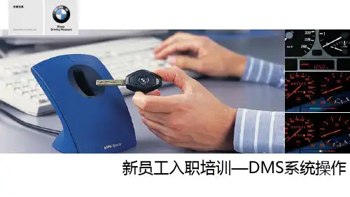
宝马服务顾问新员工入职培训-DMS培训(新)
Auto line ETK
DMS ISTA
ISPA
Wuxi Baozun Automobile New staff training Page 3
DMS操作
目录
ISPA Auto line
ETK
KSD
DMS
DWH
Wuxi Baozun Automobile New staff training Page 4
功能界面介绍
输入VIN号最后7位
可显示BSI提 示
BMW摩托车 查询维修工时 查询SRP保养/ 维修项目
查询特定车上 装载的轮胎
Wuxi Baozun Automobile New staff training Page 7
功能界面介绍
可以通过查询工时编号/工时 文本的形式查询维修所需的工 时
Wuxi Baozun Automobile New staff training Page 8
SRP项目查询—演示
1、查找DU71140该车保养所需的SRP项目 ①机油保养 ②更换空调滤芯 ③更换汽油滤芯 ④更换制动液 ⑤更换前轮制动片 2、查找SB73814该车维修所需的SRP项目 ①更换水泵 ②更换水箱 ③更换下摆臂 ④更换左前门玻璃升降器 ⑤更换空调压缩机
系统演示
Wuxi Baozun Automobile New staff training Page 18
Wuxi Baozun Automobile New staff training Page 21
功能界面介绍
打印工 单选项 工单的调度与 车辆入场登记
WIP号查询
输入维修时间 输入车辆里程
客户信 息维护
客户信 息栏
工时状态栏
《宝马BMW系培训》PPT课件

大灯清洗系统确保所有天气状况下大灯都保持最佳亮度,大灯未关时,会在清洗风档 玻璃的同时自动得到清洗。
雨量探测器,系统开启后,雨量探测器自动启动风档玻璃刮水器并自行调节刮水器频 率。
前部保险杠系统采用可复原溃缩元件可以吸收4公里/小时以下的撞机而不会发生损坏。 前后可更换的撞击吸能区可以吸收15公里/小时以下的撞机力,而不会给车身造成任何 损坏。
模仿鹰眼的“双眼”造型漂亮而犀利,大灯罩采用炭纤维增强塑料制成,即使在200公 里/小时收到石击也不会破碎。重量更轻,强度和安全性更高。
530LI采用更为安全的随动控制大灯,523LI、525LI均采用双氙气远光灯,可以照亮路 面的所有黑暗的角落。
自动行车灯(含高度动态调节,感知光线不足的情况下自动亮起及水平调节。
动风格,并且能够改善空气动力学性能。
C柱的形状模仿双门轿车,使得汽车外观更具运动风格。众多其它汽车制造商纷纷效仿 这种车型。
3年漆面保修与12年锈蚀保修
采用刚度更高的全新底盘。车身由高技术强化刚制成,提高了车身的刚度,强度和安 全性。
全铝制悬架和底盘系统提供更快的转向响应,在崎岖的道路上行驶俱备更大的舒适性。 17”铝合金轮圈改善了燃油经济性和加速性能。
CBC弯道控制系统,当汽车在快速过弯过程中轻微制动时,弯道制动控制可以增强车辆 稳定性,防止转弯时转向过度,弯道制动控制使用非对称制动压力控制形成一个起稳 定作用的反力。
DSC动态稳定控制系统,采用全球最佳牵引力控制系统之一 ,有助于使车辆控制保持在 物理极限范围内,不会出现控制过渡的情况,同时仍能保持BMW汽车的运动特性。最新 DSC升级版增加了5项新功能(雨天刹车辅助,刹车待命,坡道起步,热衰减补偿,柔 性驻车)
宝马专家版培训资料
宝马专家版培训资料1. 简介宝马专家版培训资料是宝马公司专门为其工程师和技术人员设计的一套辅助培训资料,旨在提高其员工的专业技能和知识水平,并推动企业技术创新和产品升级。
2. 培训内容概述宝马专家版培训资料涵盖了以下几个方面:2.1 宝马汽车技术概述宝马汽车技术概述涵盖了宝马公司的产品线、技术特点、市场营销等方面,使学员重点了解宝马汽车的基本情况。
2.2 宝马汽车电子控制系统宝马汽车电子控制系统是该公司的核心技术之一,该部分资料着重介绍了汽车电子控制系统的基本原理、体系结构和应用,包括舒适和安全电子系统、底盘控制系统、车身电子系统等。
2.3 宝马汽车机械系统宝马汽车机械系统包括引擎、变速器、转向系统、制动系统和悬挂系统等各种机械元件。
该部分内容主要讲解了这些机械元件的原理、功能和维修方法。
2.4 宝马汽车维修保养宝马汽车维修保养包含了汽车保养的基本操作、故障诊断和维修方法。
该部分内容希望能够帮助学员养成故障发现和处理的能力,并能够熟练掌握维修保养的基本技能和方法。
3. 培训资料形式宝马专家版培训资料形式多样,既包括纸质书籍,也包括电子文档和视频教程。
学员可以根据自己的需要选择合适的形式,并在实际工作中进行学习和实践。
4. 培训效果与优势宝马专家版培训资料具有以下优势和效果:4.1 提升员工技能培训资料内容丰富全面,包括了宝马汽车技术、电子控制系统、机械系统以及维修保养等多个方面,有效提升了员工技能和知识水平。
4.2 推动企业创新培训资料不仅注重基本知识和技能的讲解,还涉及到宝马汽车未来技术发展方向和创新产品的开发模式等,有利于推动企业的技术创新和产品升级。
4.3 改善工作效率培训资料着重介绍了故障诊断和维修保养的方法和技巧,让学员能够快速定位问题并采取正确措施,从而提高工作效率和效果。
5.宝马专家版培训资料是宝马公司技术人员的重要培训资料,它的推出对提高企业员工的技能和知识水平,推动企业技术创新具有重要意义。
BMW入职课件(创新科技1)
新员工入职培训
一)最佳重量分配50:50
轻量化材料工程学:轻盈如风.
铸铁刹车盘固定在轻量化的铝合金盘形刹车鼓托架上.
BMW5系率先应用铸铁刹车盘固定在轻量化的铝合金盘形刹车鼓托架上,这种设计使得前桥减 重约3公斤。 问题:BMW 3系原厂高性能附件中在大尺寸刹车碟表面打孔并开槽的目的是什么?
新员工入职培训
一)最佳重量分配50:50
新员工入职培训
一)最佳重量分配50:50
轻量化材料工程学:轻盈如风.
Mentor: Owen
第13页
非承载式车身. 汽车的车身可以分为非承载式车身与承载式车身两类。 非承载式车身具有梯形车架(Ladder Chassis)结构,是最早出现的车架形式。车 架和车壳作非固定连接,因此在崎岖环境下,车辆的扭曲都由坚固的梯形车架吸 收,阻止了车壳的扭动,优势非常明显。 缺点是:重量大、重心高。
Mentor: Owen
第11页
新员工入职培训
一)最佳重量分配50:50
轻量化材料工程学:轻盈如风.
Mentor: Owen
2)钢铁.
第12页
工程师们对钢铁喜爱有加,钢铁具有很好的弹性,而且可以减少震动,令 车内更加安静。另外,它非常容易焊接和成形。金属专家不断将其与新合金混 合并研究创新的高强度钢,更细、更薄的结构也能实现相同的强度,重量得以 减少,车身刚性却可以更加高。
中最轻的。
新员工入职培训
一)最佳重量分配50:50
轻量化材料工程学:轻盈如风.
Mentor: Owen
第17页
4)碳纤维(CFRP).
碳纤维强化塑料比钢铁轻80%以上,甚至比铝合金还轻30%。
碳纤维成本昂贵,制造复杂并且不易维修,
宝马4S店维修培训手册:E60 显示和操作元件 售后培训
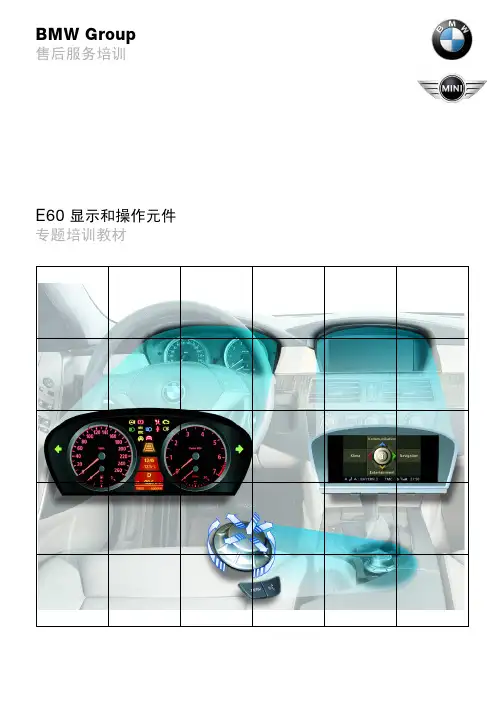
E60 显示和操作元件
转速预警显示 最高发动机转速的警告显示取决于发动机温度,由转速表显示出。 在下列表格中列出了最重要的转速预警显示内容:
发动机型号 可变预警区的起点 可变预警区的终点 固定式警示区的起点 固定式警示区的终点
汽油发动机 4200 rpm 6300 rpm 6500 rpm 7000 rpm
索引 13 14 15 16 17 18 19
20 PT-CAN K-CAN D-Bus
说明 诊断总线 安全和网关模块 前部 / 后部制动摩擦片磨损传感器 自适应巡航控制系统 ACC 动态稳定控制系统 DSC 主动转向控制 AFS 数字式发动机电子伺控系统 DME/DDE 电子变速箱控制系统 EGS/SMG 动力传动系控制器区域网络 车身控制器区域网络 诊断总线
目录
第一章
显示和操作元件 组合仪表 - 系统一览 - 系统电路图 - 部件 - 车载电脑 美规组合仪表 日规型组合仪表 - 售后服务提示 - 诊断 中央信息显示屏 CID - 系统一览 - 系统电路图 - 部件 联网服务 - 车况保养 CBS - 钥匙读取器 - 接车服务模块 SAM2 - 远程服务 1
- 16 -
E60 显示和操作元件
液晶显示屏 液晶显示屏位于车速表和转速表之间。 液晶显示屏分为两个区域。上部窗口显示时间和车外温度,也可显示 ACC 设定 车速、 CC 信息和 CBS 图像。 下部窗口用于显示车载电脑功能和行驶里程数以及 CBS 信息。 如果灯光模块内与组合仪表内的底盘号码不同,则会显示一个辨伪标记点。
-7-
E60 显示和操作元件
- 部件
组合仪表由下列部件组成: - 指针式仪表 - 指示灯和报警灯 - 液晶显示屏 - 自动变速箱或自动换档控制式手动变速箱 SMG 的程序和档位显示屏 - 用于分行驶里程表复位和车况保养 CBS 菜单操作的调节按钮 - 所连接的部件 (用于控制组合仪表内的显示内容),见系统一览及系统电路图 这一章将详细描述下列部件: - 显示区 - 指示灯和报警灯 - 液晶显示屏 - CBS 车况保养
最新BMW 全系培训资料E71 发动机技术
The new BMW TRAING Sheer
The new BMW TRAING Sheer
The new BMW TRAING Sheer
The new BMW TRAING Sheer
The new BMW TRAING Sheer
The new BMW TRAING Sheer
Sheer Driving Pleasure
The new BMW TRAING
Sheer Driving Pleasure
BMW N54双涡轮增压发动机技术
----------售后导入培训
涡轮增压器
• 涡轮增压器实质是一台空气压缩机 • 应用涡轮增压技术来提升发动机的功率 • 双涡轮增压发动机拥有两个相同涡轮增压器,发动机 中的每一个气缸都可独立完成处理涡轮增压气的工作 • 简单地陈述其原理,无非就是利用引擎经过压缩行程 后产生的高温、高速废气,通过特殊形状的名为涡旋管 室(DOWN PIPE),流入废气侧涡轮,并推动废 气侧内的涡轮叶片转动,同时,与废气侧涡轮叶片同轴 相连的生气端压缩叶轮,会对流经风格后的生气进行压 缩,压缩气体经过中央冷却器(INTERCOOLER)冷却 后,成为带有一定压力的和高密度的新鲜空气,流经节 气门和进气歧管后,进入气缸内燃烧。
Sheer Driving Pleasure
The new BMW TRAING
Sheer Driving Pleasure
The new BMW TRAING
Sheer Driving Pleasure
The new BMW TRAING
Sheer Driving Pleasure
The new BMW TRAING
Sheer Driving Pleasure
宝马内部培训材料课件
BMW开始将客户对更高人身安全性的需求纳入了车辆设计的考虑范围。这款防弹型轿车
采用直接定制的方式进行生产,车上装备的芳香尼龙纤维和防弹玻璃能够为车内乘员提供
更可靠的人身保护。
1995年 第四代5er
奥迪VS宝马 对比分析培训
BMW5系车型历史
第五代BMW 5系于2003年5月发布,它在行驶动态特性、性能、效率、舒适性、空间 诸多因素的综合与统一方面,达到了同级车型中前所未有的高度,进而建立了新的标准。 全新5系采用了全球首创的主动转向系统、铝材料和钢材料相结合的车身、全铝底盘、高 性能且高效率的汽油和柴油发,动机、6档变速箱、iDrive控制概念及其它非凡的创新特色, 就任何方面而言都具有出类拔萃的产品品质,从外部设计来看,新BMW 5系Li最显著的特 征是轴距增加了14厘米,为后排乘客提供了特别的舒适感,以及空间感所带来的乘坐乐趣。
奥迪VS宝马 对比分析培训
奥迪VS宝马 对比分析培训
白杨木板内饰
奥迪VS宝马 对比分析培训
奥迪VS宝马 对比分析培训
——7英寸显示屏幕 ——通讯、气候控制、导航、娱乐4个功能 ——但MENU键只能直接返回首页面,操作不方便
——简单明了的内饰风格
仍然采用手制动拉杆
奥迪VS宝马 对比分析培训
奥迪VS宝马 对比分析培训
奥迪VS宝马 对比分析培训
奥迪VS宝马 对比分析培训
基本参数 车型名称: 报价: 品牌: 级别: 发动机: 变速箱: 长×宽×高: 车体结构: 车身 长度: 宽度:
高度:
宝马5系 523Li豪华型 宝马5系 523Li豪华型 52.16万 华晨宝马 中大型车 2.5L 177马力 L6 6挡手自一体 4981×1846×1477 4门5座三厢车 宝马5系 523Li豪华型 4981 1846 1477
宝马4S店维修培训手册:E85 底盘 培训资料
插图 9:将上部转向柱安装在组合仪表的支撑管上
索引 1 2
说明 EPS 控制单元 转向角传感器
索引 3 4
说明 带点火开关的转向锁 方向盘机械调节装置
KT-10729
- 17 -
E85 底盘
带点火开关的转向锁、方向盘机械调节装置、电气助力单元和转向角 传感器固定在上部转向柱上。 助力单元 助力单元用于根据转向力和系统条件主动提供转向助力。 助力单元由以下部件组成: – 电机 – 蜗杆传动机构 – 控制单元 – 各种内部传感器,用于测量电机转速、转向力矩、温度和系统电压 – 作为内部转向力矩传感器导线的卷簧盒。 助力单元位于上部转向柱上,在车内带有一个保护壳体。
-3-
系统概览
E85 底盘
插图 1:不带拉线的驻车制动器操纵单元
KT-9887
索引
1 2
说明 平衡臂 装配夹
索引
3 4
说明 ASZE 单元 驻车制动器警告开关
部件
驻车制动器操纵单元由以下部件构成: – 装配凹槽 – 拉线自动调节器(ASZE 单元) – 带装配夹(拉线固定件)的平衡臂
-4-
E85 底盘
装配凹槽 装配凹槽从下面通过法兰固定在驻车制动器室的加强板上。驻车制动 器室的加强板固定在中间通道的左侧和右侧连接板上。
插图 2:装配凹槽及操纵单元的安装位置
KT-9889
索引 1 2
说明 驻车制动器室的加强板 中间通道的左侧和右侧连接板
装配凹槽内装有驻车制动器操纵单元的所有机械部件。 拉线导管以固定方式与装配凹槽连接在一起。拉线通过拉线导管引向 平衡臂。
手柄插在驻车制动器拉杆上并处于锁止状态。在不毁坏手柄的情况下 无法将其取下。
-5-
宝马E65培训资料s(4)
%0:6HUYLFH 7UDLQLQJ( &KDVVLV6HPLQDU :RUNLQJ 0DWHULDONOTEThe information contained in this training course manual is intended solely for participants of the BMW Service Training course.Refer to the relevant "Technical Service" information for any changes/supple-ments to the Technical Data.© 2001 BMW AGMünchen, Germany. Reprints of this manual or its partsrequire the written approval of BMW AG, MünchenVS-42 MFP-HGK-BRK-E65_0400ContentsPage CHAP 1Introduction1 CHAP 2Front axle2 Introduction2Front axle carrier3Arms4Stabilizer bar6Spring strut, swivel bearing and wheel bearing7Technical data9Notes on service10 CHAP 3Rear axle11 Introduction11Rear axle carrier12Swinging arm and links13Stabilizer bar14Technical data15 CHAP 4Suspension/Damping16 - Suspension16- Damping16 CHAP 5Wheels/Tyres17 Introduction17Styling overview for wheels20Wheel/tyre combinations22 CHAP 6Service brake24 Introduction24- Brake control24- Brake discs24Brake calipers27- Front brake calipers27- Rear brake calipers282-stage brake pad wear sensor29Wheel speed sensors30Notes on service32CHAP 7Parking brake33 Introduction33Functional description35System structure38- The parking brake in the bus network38- Components39Operation51Indicator lamps53Safety control57Notes on service58 CHAP 8Steering60 Introduction60Steering components61- Steering gear61- Track rod64- Steering gear connections65- Power steering pump66- Steering column67- Steering column adjustment70Steering column switch centre (SZL)71- Steering angle sensor72Chassis integration module (CIM)75IntroductionThe reliable and as yet unsurpassed double joint spring strut axle with tension struts (based on the basic E39) is used as the front axle in the new E65.The reworked and fine-tuned integral axle is once again used at the rear.The weight of the unsprung masses has been reduced by approx. 30%.The parking brake,also known as the electromechanical parking brake (EMF), is also new. It is an automated, convenience-oriented system which functions via the DSC hydraulics and an electromechanical control unit, which in turn acts on a Duo-Servo drum brake.The E65 is steered by rack and pinion power steering with a variable transmission ratio.The standard E65 rim is a lightweight forged wheel fitted with a trim.Front axleIntroductionThe tried and tested double joint spring strut axle with tension struts is used. This is characterized by its excellent features:-Almost complete track constancy over the entire compression and extension travel-Definite camber change during compression-Straight-ahead driving with0mm kingpin offset,although wide tyres are used-Anti-dive control-Few components (saving weight)These reasons ensure that nothing has surpassed this design yet.The unsprung mass is reduced which is of particular importance in vehicle construction.Nearly all the axle components are made of aluminium. This results in weight reduction of the chassis by about 30% compared to an axle made of steel components.Fig. 1: General overview of front axle KT-8756Front axle carrierThe front axle carrier is now also manufactured using light alloy. It consists of cast alloy preformed sections which are welded into the extruded sections.A reinforcement plate is screwed on to increase the transversal rigidity of the front car.This has a positive effect on the handling, acoustics and crash performance.KT-7956 Fig. 2: Front axle carrier with wheel suspensionIndex Description Index Description1Reinforcement plate4Swivel bearing2Control arm5Wheel bearing3T ension strut6Axle carrierFor selected materials, a high elongation after fracture, as well as sufficiently high tensile strength and yield point, especially when there is strong load, is achieved.ArmsThe arms are located in accordance with the E39basic axle with a wishbone and a tension strut containing a hydro mount at the front.The layout of the arms,combined with the track rods fitted in front of the wheel centre,guarantees balanced steering when cornering.The hydro mount in the tension strut damps through its fluid filling wheel vibrations. Vibrations which are felt on the steering wheel are thus avoided.Fig. 3: Hydro mount in the tension strutIndex Description 1Fluid ductsKT -8684KT-7791Fig. 4: Wheel suspensionIndex Description Index Description4Control arm1Pendulum support onstabilizer bar2Stabilizer bar5Coupling rod for ride levelsensor3T ension strut6Ride level sensorStabilizer barThe standard stabilizer bar is designed as a tubular stabilizer bar , which minimizes the body tilt inclination. It is directly connected to the spring strut by means of stabilizer links to achieve the best performance level.The high connection on the spring strut is selected so that when you are driving straight ahead and when driving over a bump on one side, nothing can cause the spring strut to turn. This would make driving straight ahead bumpy .The active roll stabilizer bar (ARS), also known as Dynamic Drive, is available as an option.Fig. 5: General overview of front axle from belowIndex Description 1Stabilizer barKT -8875Spring strut, swivel bearing and wheel bearingThe support tube and the swivel bearing are two parts which are bolted together .The support tube is made of aluminium and has a special feature on the side which is used to fix it into the swivel bearing in the correct position. The support tube and swivel bearings are produced in left and right versions, and are identified by a sticker .The wheel bearing/hub unit is bolted onto the swivel bearing.Fig. 6: Spring strut, swivel bearingIndex Description IndexDescription 1Support tube 3Locating fixture2Swivel bearingKT -8874Upper mountFig. 7: Upper mountA laser measurement is carried out at the line end of thebodyshell production. Once the specific position of the spring strut towers has been determined and the values measuredhave been recorded,a centering hole is punched.The centering pin in the mount is inserted in this hole to ensure the correct camber and camber variation (delta value ∆) between the left and right hand sides with very low tolerances.Index Description 1Centering pinKT -8870Technical dataThe following table shows the technical data in relation to the wheel sizes.Wheels8 J x 178 J x 18Caster angle8º 7'± 30'Caster offset (mm)26Camber-6'± 20'T otal toe-in10'± 8'T oe difference angle1º 27'± 30'Kingpin inclination15º 26'± 30'Rim offset (mm)24Kingpin offset (mm)0T rack (mm)1578Maximum steering wheel Inner 40º 40'Outer 33º 26'KT-8972 Fig. 8: Front axle from the frontNotes on serviceT oe adjustmentThe track is set externally using a clamping device on the track rods.Camber adjustmentThe camber is set on the spring-strut support bearing. If it is necessary to set this in the workshop, the centering pin is removed and the camber correction is carried out using the slots in the spring strut tower.Therefore adjustments of±30'are possible.Rear axleIntroductionA particular focal point of running gear development is weight reduction for the purpose of achieving optimum comfort and safety properties.Fig. 9: General view of rear axleThe rear axle is designed as a modified, kinematically and aerodynamically improved integral axle.KT-8873Rear axle carrierThe rear axle carrier is a welded structure made of hydraulically formed aluminium sections and cast aluminium joints or nodes.The rear axle bearings have larger dimensions than in the E38.The rear axle differential (final drive) is mounted flexibly in the rear axle carrier ,now with two mount points at the front and only one at the rear . This modification offers advantages with regard to the acoustics and vibration characteristics. The rear rubber mount features kidney-shaped recesses to allow for varying vibrations in horizontal or vertical direction.Note:Particular care must be taken to ensure that the rubber mounts are installed in the correct position.The additional empty bush only serves the purpose of ensuring stability of the rear cross member cross section.Fig. 10: View of rear axleIndex Description IndexDescription1Rear cross member 3Rear axle differential bearing bush, front 2Rear axle differential bearing bush, rear4Thrust rodKT -8872Swinging arm and linksThe swinging arm and links are made of aluminium and adapted geometrically to the driving requirements of the E65. Camber and toe curve at total spring compression and deflection, pitch compensation (anti-dive) and brake support angle are values that, as the result of slight changes to the individual link points,have a decisive influence on vehicle handling. When observed on the lifting hoist, the swinging arm has a very twistedappearance. Compressed in the normal position, it is aligned parallel to the road and creates an air guidance effect for favourable aerodynamic flow of the air to the rear area of the vehicle.Fig. 11: Wheel suspension rear axleIndex Description IndexDescription 1Control arm 4Upper traction strut 2Integral link 5Wheel carrier3Swinging armKT -8871Fig. 12: Wheel suspensionStabilizer barA stabilizer bar is always fitted on the rear axle.The stabilizer bar is connected by means of stabilizer links between the rear axle carrier and swinging arms.The connection at the swinging arm is now designed as an axial ball joint.It is secured by means of a taper seat with nut and T orx socket head screw .IndexDescription IndexDescription 1T raction strut 4Swinging arm 2Control arm 5Stabilizer link3Level sensorKT -7957Technical dataFig. 13: General view of rear axle from aboveT oe adjustmentThe toe is adjusted by means of an eccentric element at the front upper traction strut.Camber adjustmentThe camber is adjusted by means of an eccentric element on the inner swinging arm at the connection to the axle carrier .Steel springWheel 8J x 17Wheel245/55 R17T rack width 1582T otal toe-in 18'±10'Wheel axle angle 0º±12'Level in normal position 620±1 mm Vehicle inclination0±1 mm Camber in normal position+1º30'± 20'KT -8757Suspension/Damping-SuspensionThe E65 features a conventional helical or coil compression spring as standard on the front and rear axle. It has a linear characteristic. Both at the front as well as at the rear axle, the springs are combined with the shock absorbers to form the spring strut (McPherson struts).The optional pneumatic spring (standard on the 12-cylinder version) on the rear axle serves the purpose of adjusting the level at high payloads. It has the advantage of maintaining a constant level of the vehicle irrespective of the load status.As a result, the full spring compression and deflection travel range is made available.A pneumatic spring is not fitted on the front axle as the load differences are not so great at this point.T wo-axle pneumatic springs will be used at BMW only if it is necessary to adapt the level of the vehicle to certain operating conditions. Example X5, model year 2002-DampingThe E65 is equipped with two-tube gas pressurized shock absorbers as standard. As on the E39, the E65 features aluminium McPherson struts at the front at rear. A locking device/positioning aid is used on the front axle. The clamping area of the spring struts is shot-peened to increase the strength. In view of the improved response characteristics and in order to avoid cavitation, the low pressure dampers are filled with nitrogen at a pressure of 5 bar. An EDC-K in connection with or without dynamic drive can be ordered optionally.EDC-K and dynamic drive are explained in separate chapters.Wheels/T yresIntroductionThe E65 is fitted as standard with light-alloy wheels. The spare wheel is designed in the same way as the road wheels.The standard rim of the E65is a weight-optimized forged wheel (Styling 90) which is partly covered by a glass-fibre-reinforced plastic trim. The object of this composite design is to minimise the unsprung, rotating masses while simultaneously achieving good aerodynamic properties and an attractive, stylish visual appearance.KT-8458 Fig. 14: Lightweight forged wheel with trimIndex Description Index Description1Lightweight forged wheel2T rimNote:For all regular operations, e.g. wheel removal and installation, tyre and valve removal, the trim can and should remain on the wheel.The trim must be in place when the wheel is being balanced.In the event of damage or heavy accumulation of dirt between the wheel and the trim, the latter can be easily removed and refitted by hand, without the aid of any tools.The wheel studs are M14 x 1.5 mm hexagon-socket-head cap screws with14mm hexagon sockets.This has helped to reduce the material and thus the weight of the wheel. The studs are tightened to a torque of 140 Nm.Description WeightConventional stud M14 19 mm A/F86 gNew stud M14 hexagon socket 14 mm69 gBalance weights:Adhesive weights are used on the E65 for balancing purposes.These weights are cut to length in series assembly as seamless weights as needed and stuck to the inside of the rim on the designated precision-cut areas for dynamic balancing.Fig. 15: Cross-section of lightweight forged wheel with trimVarious light-alloy wheels are available as special equipment (SE).Index Description1Bonding surfaces for balance weightsKT -8459Styling overview for wheelsStyling no.Description View908J x 17Forged wheel with trimKT-8437 918J x 18Cast aluminiumKT-8438 929J x 19 Front10J x 19 RearForged wheelKT-8439 938J x 18Cast aluminiumKT-8440 948J x 18Cast aluminiumKT-8441Further wheels are available through the Parts Department as optional extras (OE).For example:959J x 19 Front 10J x 19 Rear Cast aluminiumStyling no.Designation View899J x 19 Front 10J x 19 Rear Cast aluminium1019J x 20 Front 10J x 20 Rear Alloy wheelscrewed in 2 parts32 BR (Brilliantpaint finish)9J x 20 Front 10J x 20 Rear Cast aluminiumKT -8442KT -8436KT -8789KT -8790Wheel/tyre combinations745i U S-TTO EO ES ES EO EO E-O EO EO EO ESS760i **---SSS ES EO E O E ---O E O E --740d **-S S S ES ES ES EO E O E -O E O E O E O E --745i-S S S E S E S ES EO E O E -O E O E O E O E --735i -S S S E S E S E S E O E O E O E O E O E O E O E --730d *S S E S E S E S E S E S E O E O E O E O E O E O E O E --730i ***S S E S E S E S E S E S E O E O E O E O E O E O E O E --I S m m20242424242424242420242424242424U d y n m m2140214021402140214021452145214521352140214021402140214021402140❆x x x x x xx xxx xx R Fx x x xx V c l .W W W W W W W Y Y Q /T /H Q /T /H Q /T /H Q /T /HQ /T /H VV L I 9910210210010098101959899102102100100100100W h e e l7 1/5 J x 17 H 2/E H 28 J x 17 H 2/E H 28 J x 17 E H 28 J x 18 H 2/E H 28 J x 18 E H 29 J x 19 H 2/E H 210 J x 19 H 2/E H 29 J x 20 H 2/E H 210 J x 20 H 2/E H 27 1/5 J x 17 H 2/E H 28 J x 17 H 2/E H 28 J x 17 E H 28 J x 18 H 2/E H 28 J x 18 E H 28 J x 18 H 2/E H 28 J x 18 E H 2T y r eS u m m e r225/60 R 17245/55 R 17245/55 R 17 **245/50 R 18245/50 R 18 **245/45 R 19275/40 R 19245/40 R 20275/35 R 20W i n t e r225/60 R 17 M +S245/55 R 17 M +S 245/55 R 17 M +S **245/50 R 18 M +S245/50 R 18 M +S **A l l s e a s o n245/50 R 18 M +S245/50 R 18 M +S **Index Description Index Description*From 03/02RF Runflat(tyre with flat-running properties)onlyin conjunction with DDS (RPA) or RDC**From 09/02V cl.Speed class***From 03/03Udyn Dynamic wheel diameterLI Load index IS Inset, wheel offset❆Snow chainpossibleService brakeIntroductionThe E65 features a hydraulic dual-circuit brake system with "black/white" distribution. One brake circuit for the front axle and one brake circuit for the rear axle. The brake power has been adapted to the weight and the increased driving performance.The gross weight rating of the740i is2520kg and 2705 kg for the 760i. The brake system offers the high safety reserves characteristic of BMW. The weight-to-power ratio, service life of the brake pad and brake disc as well as the noise characteristics have been improved.-Brake controlThe brake system is controlled in the conventional manner with a vacuum booster and tandem master brake cylinder. The design is based on an 8"/9" aluminium brake booster with tandem master brake cylinder and brake fluid reservoir.The brake booster is now smaller as brake power assistance is controlled by the engine in conjunction with a vacuum pump on the M57, M67, N62 and N73.DOT4 brake fluid is used in all E65 models.-Brake discsAll E65vehicles will be equipped on the front and rear axle with inner-vented brake discs made of high carbon cast iron. The brake discs are coated with Geomet over the entire surface (EU Directive relating to freedom of chromium VI as from 7/2003).The Geomet coating is a zinc-aluminium surface coating (microfine scaled surface pattern) that is sprayed on and baked at 300 ºC. It is environmentally compatible and features outstanding corrosion protection properties. On the friction surface, the protective coating is worn down without any changes in the coefficient of friction at the brake pads.All other surfaces, e.g. wheel mount, brake disc nave and ventilation channels retain their corrosion-resistant surface over their entire service life.Note:An initial scraping sound is normal and will have disappeared after five to ten braking operations.Brake guardThe ventilation-optimized brake guards on the front axle and rear axle are made of aluminium. They are shaped such that water can drain off most effectively.The threaded connections of the guards at the swivel bearings are mounted in rubber to avoid noise. A rubber element that prevents noise transmission is also fitted between the guard plate and swivel bearing.The sectional rubber element 1 on the rear axle serves the purpose of covering the duo-servo drum brake.KT-7788 Fig. 16: Brake guard on wheel carrierIndexDescriptionIndex Description1Rubber element between wheel carrier and guard plate3Brake guard of rear axle2Wheel carrierBrake calipers-Front brake calipersThe housing of the front axle brake calipers is made of aluminium. The frame surrounding the brake caliper preventsV-shaped spread of the brake caliper as the result of contact pressure on the brake disc.The brake caliper holder is made of zinc-nickel coated spheroidal cast iron.A cover has been fitted to improve the appearance of the brake caliper. The brake pad thickness can be measured in the usual way through the hole in the centre.The retaining spring for fixing the brake caliper in position is firmly connected to the cover.Fig. 17: Front axle brake caliperIndex Description Index Description1Opening for measuringbrake pad thickness 4Spheroidal cast ironmounting bracket2Cover5Aluminium housing3Retaining springKT-77863different brake calipers will be installed on the front axle of the E65.In view of the high weight and the distinctly improved driving performance of the 760i and the thus associated higherdemands made on the braking power ,a 2-piston floating caliper is installed in the EU version.- Rear brake calipersThe brake calipers on the rear axle are made of zinc-nickel coated spheroidal cast iron based on the known version.A total of 3 different brake calipers will be installed on the rear axle.Brake caliper designationVehicle type Minimum size of rim 1-piston floating caliperFNR-Al 60/30/324730d, 730i, 735i 16",E65axle concept (trackrod head)17"1-piston floating caliper FNR-Al 60/30/348740d, 745i,760i (export)17"2-piston floating caliperFN 42/36/374760i (Europe)18"Brake caliper designationVehicle type Minimum size of rim 1-piston floating caliperFN 46/20/324730d, 730i, 735i 16"E65 axle concept(track rod head,front axle)17"1-piston floating caliper FN 46/24/345740d, 745i, 760i (export)17"1-piston floating caliperFN 46/24/370760i (Europe)18"2-stage brake pad wear sensorThe 2-stage brake pad wear sensors at the front left and rear right relay their voltage signals to the DSC control unit where they are used for continuous calculation of the brake pad wear in the DSC control unit.In the first stage, the brake pad wear indicator operates in the same way as on previous models. A resistor has now been additionally integrated in the second stage. The control unit is informed of the current wear status based on the changed voltage measurement.The first stage of the wear indicator is activated at 6 mmremaining brake pad,the second stage at 4mm remaining brake pad.Fig.18:Circuit diagram of brake padwear sensor Fig. 19: Sectional viewIndexDescription Index Description 1Stage 13Brake disc 2Stage 24Brake pad wear sensorKT -8882KT -8881With these two different voltages, the probable total service life of the brake pads can be determined with the aid of a computing model in the control unit.The remaining kilometrage of the brake pads can be shown as a kilometre reading in the control display as required. The remaining kilometrage is calculated from the input variables: wheel speed, distance, brake pressure, brake disc temperature and brake operating time.After switching off the ignition, the calculated remaining kilome-trage for the front axle and rear axle brake pads is stored in the DSC control unit and serves as a start value when the vehicle is placed into operation again.The service proposals are shown separately in the control display for the front axle and rear axle. The brake pad thickness can be checked through the mounted wheel in the usual way using a special tool.Wheel speed sensorsA new wheel speed sensor,that operates in accordance with the Hall principle, is used. A special feature of this sensor is that it detects forward and reverse movement.The sensor contains three Hall-effect elements accommodated next to each other in a housing.The signals of the first and of the third Hall element form a differential signal for determining the signal frequency and the air gap(clearance)to the sensor wheel. Clockwise or anticlockwise rotation is detected by means of the temporal offset of the signal from the middle element with respect to the differential signal.Fig. 20: Wheel speed sensor and signalsThe additional signals of the air gap (clearance) and thedirection of rotation are output via the pulse width of the digital signal.The signals processed in the sensor are transferred via acombined ground and data line to the control unit. It is not the voltage level that is decisive on the data line but rather the flow of current. This gives rise to a reoccurring data telegram that uses two different amp ratings.The 14 mA level contains the information - speed, direction of rotation and air gap.The 7 mA level serves as an evaluation current for the fault memory .IndexDescription IndexDescription 1Hall-effect element 3Signal of centre Hall element2Differential signal KT -8885In contrast to the previous sensors, when the vehicle is stationary, a pulse is sent every 740 ms thus indicating the sensor availability.Basic signal when vehicle is stationary14 mA7 mA740 msStandstill signalKT-8967 Fig. 21: Current flow data telegramNotes on serviceThe tightening torque requirements of the fastening screws on the brake hoses and pipes have been changed (see TIS tight-ening torques).After replacing the brake pads, the residual kilometrage stored in the DSC control unit must be reset to a new start value separately for each axle by means of the diagnosis tester. When a DSC control unit is changed,the diagnosis tester can be used to enter the specified remaining kilometrage for the front axle and rear axle brake pads in the new control unit.Parking brakeIntroductionWhy a new system?The parking brake, also termed as the electromechanical parking brake (EMF), will be used for the first time in series production in the E65.In principle, the parking brake is used to secure the stationary vehicle to prevent it rolling away. It firmly brakes (locks) the vehicle when parked.The new parking brake that replaces the previous handbrake or foot-operated parking brake is an automatic, comfort-oriented parking brake system with which the driver can apply and release the parking brake by pressing a push-button.The system is realized in compliance with requirements charac-teristic of BMW:-Exclusion of all safety-critical statuses-Optimum functionality-Maximum system availability-Best comfort and convenienceKT-7993 Fig. 22: Parking brake push-button in instrument panelThe task of the system is to lock the vehicle mechanically when parked and,in addition to the service brake,to provide a further independent brake system as required by law.Added to this,the parking brake offers additional comfort and safety functions.KT-8843 Fig. 23: Parking brake componentsIndex Description Index Description1EMF actuator3Drum brake2Bowden cableFunctional descriptionBasic functionsThere are two different types of parking brake functions depending on the operating status of the vehicle.1.Locking (brake applied):1.With the engine running or the vehicle rolling,with the aid ofthe DSC hydraulics, the parking brake acts on the discbrakes of the front axle and rear axle.2.When the engine is not running and the vehicle is stationary,with the aid of the electromechanical actuator in connection with bowden cables, the parking brake acts on the duo-servo drum brake of the rear axle.The actuator is located in the luggage compartment floor between the spare wheelrecess and stiffener wall of the rear bench seat.The parking brake is always applied as defined in the control unit when the actuator is activated.2.Dynamic braking:Defined braking(deceleration)takes place via the DSC system if the parking brake push-button is pressed while driving.The braking procedure is monitored by the ABS control function and takes place for as long as the push-button is pressed.Comfort functionAutomatic holdWith this comfort function that is selected via the controller,after braking down to a standstill, the vehicle is hydraulically held by the parking brake (DSC). The wheel brakes are released by pressing the accelerator pedal and the vehicle begins to move. Automation of the hold and release function assists hill starts as it prevents the vehicle rolling back (hill hold).Emergency releaseA mechanical emergency release facility is provided in order to be able to release the parking brake in the event of the actuating unit failing or insufficient power supply. By way of direct manual intervention in the gear mechanism, it is possible to release the mechanical actuating unit and thus the duo-servo drum brake using an emergency release tool and open-ended spanner from the vehicle tool kit.Special functionIn order to increase the availability of the optimum duo-servo braking effect, the brake linings are bedded down at defined intervals during vehicle operation.The bedding down procedure is designed to eliminate any corrosion spots on the duo-servo brake shoes and on the brake drums. The brake lining bedding down procedure takes place approx. every 1000 km or once a month.300bedding down procedures result in brake shoe wear in the range from 0.3 to 0.5 mm.The procedure takes place automatically and should be noticed by the driver as little as possible. The brake linings are bedded down by applying the parking brake actuating unit with reduced holding force. The braking force at the spindle during the brake lining bedding down procedure is 800 N (20% of the maximum actuating force).。