VP-240 由令
富士通PRIMERGY RX4770 M4四路机架式服务器数据手册说明书
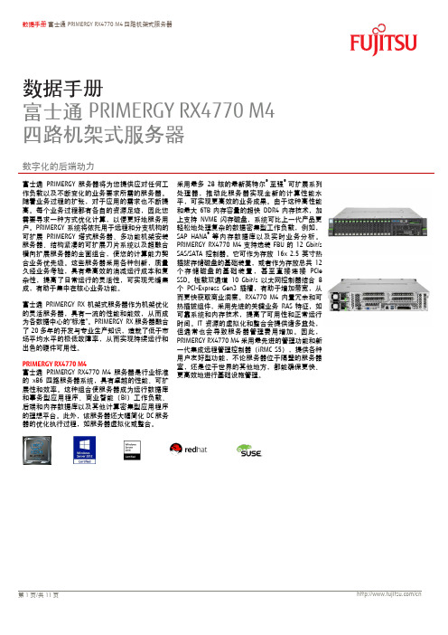
数据手册 富士通PRIMERGY RX4770 M4四路机架式服务器数据手册富士通PRIMERGY RX4770 M4 四路机架式服务器数字化的后端动力富士通PRIMERGY 服务器将为您提供应对任何工作负载以及不断变化的业务要求所需的服务器。
随着业务过程的扩张,对于应用的需求也不断提高。
每个业务过程都有各自的资源足迹,因此您需要寻求一种方式优化计算,以便更好地服务用户。
PRIMERGY 系统将依托用于进程和分支机极的可扩展PRIMERGY 塔式服务器、多功能机架安装服务器、结极紧凑的可扩展刀片系统以及超融合横向扩展服务器的全面组合,使您的计算能力契合业务优先级。
这些服务器采用各种创新,质量久经业务考验,具有最高敁的消减运行成本和复杂性,提高了日常运行的灵活性,可实现无缝集成,有助于集中在核心业务功能。
富士通PRIMERGY RX 机架式服务器作为机架优化的灵活服务器,具有一流的性能和能敁,从而成为各数据中心的“标准”。
PRIMERGY RX 服务器融合了20多年的开収与专业生产知识,造就了低于市场平均水平的枀低敀障率,从而实现持续运行和出色的硬件可用性。
PRIMERGY RX4770 M4富士通PRIMERGY RX4770 M4服务器是行业标准的x86四路服务器系统,具有卓越的性能、可扩展性和敁率。
这种组合使服务器成为运行数据库和事务型应用程序、商业智能(BI )工作负载、后端和内存数据库以及其他计算密集型应用程序的理想平台。
此外,该服务器还大幅简化DC 服务器的优化执行过程,如服务器虚拟化或整合。
采用最多28核的最新英特尔® 至强®可扩展系列处理器,推动此服务器实现全新的计算性能水平,可实现更高敁的业务成果。
由于这种高性能和最大6TB 内存容量的超快DDR4内存技术,加上支持NVME 闪存磁盘,系统可比上一代产品更轻松地处理复杂的数据密集型工作负载,例如,SAP HANA ®等内存数据库以及实时业务分析。
国科环宇OpenVPX产品手册2014版

76
OV8301 3U 图像视频后 IO 板
78
OV8302 3U 标准配置后 IO 板
80
OpenVPX产品简介
OpenVPX是新一代高性能、高可靠计算机标准,国科环宇作为VITA组织会员之一, 秉承满足客户需求的理念,持续自主研发针对航空、航天、车载、舰载等恶劣环 境应用的OpenVPX标准高可靠计算机系列产品。国科环宇提供从整机到主机板、 功能板、接口板和背板等各种部件,以及全面的软件支持和技术服务。
AD接口板
OV4311 3U 四通道2.5Gsps
AD接口板
电源板
OV4312 3U QSFP接口板
后IO板
OV6301 3U 7槽0.85"背板
OV5300 3U K7 FPGA载板
OV5301 3U ProASIC3L FPGA载板
OV5311 3U XMC/PMC载板
OV7301 3U 180W电源板
整机
机箱
OV9370
OV9310Байду номын сангаас
OV93T0
OV96T0
OV96T1
3U 7槽导冷高可靠计算机 高可靠嵌入式GPU计算机 3U 7槽风冷调试平台 6U 8槽风冷上架平台 6U 5槽风冷上架平台
主机板
OV1300
OV1301
OV1302
3U 7槽1.0"导冷机箱 3U 7槽0.85"导冷机箱 3U 4槽 0.85"导冷机箱
OV8300 3U 管理控制后IO板
OV8301 3U 图像视频后IO板
OV8302 3U 标准配置后IO板
1
环境适应性等级
散热方式
LEVEL 0
IR公司_大功率MOS管选型

I DContinuous Drain Current(A)70°Micro3Surface Mount PackagesV (BR)DSSDrain-to-Source Breakdown Voltage (V)R DS(on)On-State Resistance ()ΩI D Continuous Drain Current 25°C(A)R ΘMax.Thermal Resistance (°C/W)1FaxonDemand Number Case Outline KeyPartNumberPD Max.PowerDissipation (W)N-ChannelLogic LevelIRLML2402*912570.54200.25 1.20.95230H1IRLML2803912580.54300.251.20.93230P-ChannelLogic LevelIRLML6302*912590.54-200.6-0.62-4.8230H1IRLML5103912600.54-300.6-0.61-4.8230* Indicates low VGS(th), which can operate at VGS = 2.7VMeasured at ambient for Micro3, Micro6, Micro8, SO-8, and SOT-223 package styles. All others measured at case.1Micro3SO-8D-PakD -PakSOT-227Micro6SOT-223Micro82 Illustrations not to scaleI DContinuous Drain Current(A)70°Micro6Surface Mount PackagesV (BR)DSSDrain-to-Source Breakdown Voltage (V)R DS(on)On-State Resistance ()ΩI D Continuous Drain Current 25°C(A)R ΘMax.Thermal Resistance (°C/W)1FaxonDemand Number Case Outline KeyPartNumberPD Max.PowerDissipation (W)N-ChannelLogic LevelIRLMS1902915401.7200.10 3.2 2.675H2IRLMS1503915081.7300.103.22.675P-ChannelLogic LevelIRLMS6702*914141.7-200.20-2.3-1.975H2IRLMS5703914131.7-300.20-2.3-1.975* Indicates low VGS(th), which can operate at VGS = 2.7VMeasured at ambient for Micro3, Micro6, Micro8, SO-8, and SOT-223 package styles. All others measured at case.1Micro3SO-8D-PakD -PakSOT-227Micro6SOT-223Micro82 Illustrations not to scaleI DContinuous Drain Current(A)70°Micro8Surface Mount PackagesV (BR)DSSDrain-to-Source Breakdown Voltage (V)R DS(on)On-State Resistance ()ΩI D Continuous Drain Current 25°C(A)R ΘMax.Thermal Resistance (°C/W)1FaxonDemand Number Case Outline KeyPart NumberP D Max.PowerDissipation (W)N-Channel Logic LevelIRF7601* 912611.820 0.035 5.7 4.6 70 H3IRF7603 912621.830 0.035 5.6 4.5 70Dual N-Channel Logic LevelIRF7501* 912651.220 0.135 2.4 1.9 100 H3IRF7503 912661.2530 0.135 2.4 1.9 100P-Channel Logic LevelIRF7604* 912631.8-20 0.09 -3.6 -2.9 70 H3IRF7606 912641.8-30 0.09 -3.6 -2.9 70Dual P-Channel Logic LevelIRF7504* 912671.25-20 0.27 -1.7 -1.4 100 H3IRF7506 912681.25-30 0.27 -1.7 -1.4 100Dual N- and P-Channel Logic LevelIRF7507* 912691.2520 0.1352.4 1.9 100 H3-20 0.27 -1.7 -1.4IRF7509 912701.2530 0.135 2.4 1.9 100-30 0.27 -1.7 -1.4* Indicates low VGS(th), which can operate at VGS = 2.7VMeasured at ambient for Micro3, Micro6, Micro8, SO-8, and SOT-223 package styles. All others measured at case.1Micro3SO-8D-Pak D -PakSOT-227Micro6SOT-223Micro8 2 Illustrations not to scaleI DContinuous Drain Current(A)70°SO-8Surface Mount PackagesV (BR)DSSDrain-to-Source Breakdown Voltage (V)R DS(on)On-State Resistance ()ΩI D Continuous Drain Current 25°C(A)R ΘMax.Thermal Resistance (°C/W)1FaxonDemand Number Case Outline KeyPart Number P D Max.PowerDissipation (W)N-ChannelIRF7413913302.5300.011139.250H4IRF7413A 916132.5300.0135128.450IRF9410915622.5300.0375.850Dual N-ChannelIRF7311914352.0200.029 6.6 5.362.5H4IRF7313914802.0300.029 6.5 5.262.5IRF7333917002.0300.10 3.5 2.862.5917002.0300.050 4.9 3.962.5IRF9956915592.0300.103.52.862.5Dual P-ChannelIRF7314914352.0-200.058-5.3-4.362.5H4IRF7316915052.0-300.058-4.9-3.962.5IRF9953915602.0-300.25-2.3-1.862.5* Indicates low VGS(th), which can operate at VGS = 2.7VMeasured at ambient for Micro3, Micro6, Micro8, SO-8, and SOT-223 package styles. All others measured at case.1Micro3SO-8D-PakD -PakSOT-227Micro6SOT-223Micro82 Illustrations not to scaleI DContinuous Drain Current(A)70°SO-8Surface Mount PackagesV (BR)DSSDrain-to-Source Breakdown Voltage (V)R DS(on)On-State Resistance ()ΩI D Continuous Drain Current 25°C(A)RΘMax.ThermalResistance(°C/W)1FaxonDemand Number Case Outline KeyPart NumberP D Max.PowerDissipation (W)Dual N- and P-ChannelIRF7317 915682.020 0.029 6.6 5.3 62.5 H42.0-20 0.058 -5.3 -4.3 62.5IRF9952 915622.030 0.103.5 2.8 62.5915622.0-30 0.25 -2.3 -1.8 62.5IRF7319 916062.030 0.029 6.5 5.2 62.52.0-30 0.058 -4.9 -3.9 62.5* Indicates low VGS(th), which can operate at VGS = 2.7VMeasured at ambient for Micro3, Micro6, Micro8, SO-8, and SOT-223 package styles. All others measured at case.1Micro3SO-8D-Pak D -PakSOT-227Micro6SOT-223Micro8 2 Illustrations not to scaleI DContinuous Drain Current(A)70°SO-8Surface Mount PackagesV (BR)DSSDrain-to-Source Breakdown Voltage (V)R DS(on)On-State Resistance ()ΩI D Continuous Drain Current 25°C(A)R ΘMax.Thermal Resistance (°C/W)1FaxonDemand Number Case Outline KeyPart Number P D Max.PowerDissipation (W)N-ChannelLogic LevelIRF7401912442.5200.0228.77.050H4IRF7201911002.5300.0307.0 5.650IRF7403912452.5300.0228.55.450Dual N-ChannelLogic LevelIRF7101908712.0200.10 3.5 2.362.5H4IRF7301912382.0200.050 5.2 4.162.5IRF7303912392.0300.050 4.9 3.962.5IRF7103910952.0500.1303.02.362.5P-ChannelLogic LevelIRF7204911032.5-200.060-5.3-4.250H4IRF7404912462.5-200.040-6.7-5.450IRF7205911042.5-300.070-4.6-3.750IRF7406912472.5-300.045-5.8-3.750IRF7416913562.5-300.02-10-7.150* Indicates low VGS(th), which can operate at VGS = 2.7VMeasured at ambient for Micro3, Micro6, Micro8, SO-8, and SOT-223 package styles. All others measured at case.1Micro3SO-8D-PakD -PakSOT-227Micro6SOT-223Micro82 Illustrations not to scaleI DContinuous Drain Current(A)70°SO-8Surface Mount PackagesV (BR)DSSDrain-to-Source Breakdown Voltage (V)R DS(on)On-State Resistance ()ΩI D Continuous Drain Current 25°C(A)R ΘMax.Thermal Resistance (°C/W)1FaxonDemand Number Case Outline KeyPart Number P D Max.PowerDissipation (W)Dual P-ChannelLogic LevelIRF7104910962.0-200.250-2.3-1.862.5H4IRF7304912402.0-200.090-4.3-3.462.5IRF7306912412.0-300.10-3.6-2.962.5Dual N- and P-Channe Logic LevelIRF7307912421.4200.050 4.3 3.490H4-200.090-3.6-2.9IRF7105910972.0250.1093.5 2.862.52-250.25-2.3-1.862IRF7309912432.0300.050 4.9 3.962.5-300.10-3.6-2.9* Indicates low VGS(th), which can operate at VGS = 2.7VMeasured at ambient for Micro3, Micro6, Micro8, SO-8, and SOT-223 package styles. All others measured at case.1Micro3SO-8D-PakD -PakSOT-227Micro6SOT-223Micro82 Illustrations not to scaleI DContinuous Drain Current(A)70°SOT-223Surface Mount PackagesV (BR)DSSDrain-to-Source Breakdown Voltage (V)R DS(on)On-State Resistance ()ΩI D Continuous Drain Current 25°C(A)R ΘMax.Thermal Resistance (°C/W)1FaxonDemand Number Case Outline KeyPart Number P D Max.PowerDissipation (W)N-ChannelIRFL4105913812.1550.045 3.7 3.060H6IRFL110908612.01000.54 1.50.9660IRFL4310913682.11000.20 1.6 1.360IRFL21090868 2.02001.50.960.660IRFL214908622.02502.00.790.560P-ChannelIRFL9110908642.0-1001.2-1.1-0.6960H6N-ChannelLogic LevelIRLL3303913792.1300.031 4.6 3.760H6IRLL014N 914992.1550.14 2.0 1.660IRLL2705913802.1550.043.83.060* Indicates low VGS(th), which can operate at VGS = 2.7VMeasured at ambient for Micro3, Micro6, Micro8, SO-8, and SOT-223 package styles. All others measured at case.1Micro3SO-8D-PakD -PakSOT-227Micro6SOT-223Micro82 Illustrations not to scaleI DContinuous Drain Current(A)100°D-PakSurface Mount PackagesV (BR)DSSDrain-to-Source Breakdown Voltage (V)R DS(on)On-State Resistance ()ΩI D Continuous Drain Current 25°C(A)R ΘMax.Thermal Resistance (°C/W)1FaxonDemand Number Case Outline KeyPart Number P D Max.PowerDissipation (W)N-ChannelIRFR33039164257300.0313321 2.2H7IRFR024N9133638550.0751610 3.3IRFR41059130248550.0452516 2.7IRFR12059131869550.0273723 1.8IRFR11090524251000.54 4.3 2.75IRFR120N 91365391000.219.1 5.8 3.2IRFR391091364521000.11159.5 2.4IRFR2109052625200 1.5 2.6 1.75IRFR22090525422000.8 4.833IRFR21490703252502 2.2 1.45IRFR2249060042250 1.1 3.8 2.43IRFR3109059725400 3.6 1.7 1.15IRFR3209059842400 1.8 3.123IRFR42090599425003 2.4 1.53IRFRC2090637426004.421.33* Indicates low VGS(th), which can operate at VGS = 2.7VMeasured at ambient for Micro3, Micro6, Micro8, SO-8, and SOT-223 package styles. All others measured at case.1Micro3SO-8D-PakD -PakSOT-227Micro6SOT-223Micro82 Illustrations not to scaleI DContinuous Drain Current(A)100°D-PakSurface Mount PackagesV (BR)DSSDrain-to-Source Breakdown Voltage (V)R DS(on)On-State Resistance ()ΩI D Continuous Drain Current 25°C(A)R ΘMax.Thermal Resistance (°C/W)1FaxonDemand Number Case Outline KeyPart Number P D Max.PowerDissipation (W)P-ChannelIRFR55059161057-550.11-18-11 2.2H7IRFR53059140289-550.065-28-18 1.4IRFR90149065425-600.5-5.1-3.25IRFR90249065542-600.28-8.8-5.63IRFR91109051925-100 1.2-3.1-25IRFR91209052042-1000.6-5.6-3.63IRFR9120N 9150739-1000.48-6.5-4.1 3.2IRFR92109052125-2003-1.9-1.25IRFR92209052242-200 1.5-3.6-2.33IRFR92149165850-250 3.0-2.7-1.7 2.5IRFR93109166350-4007.0-1.8-1.12.5* Indicates low VGS(th), which can operate at VGS = 2.7VMeasured at ambient for Micro3, Micro6, Micro8, SO-8, and SOT-223 package styles. All others measured at case.1Micro3SO-8D-PakD -PakSOT-227Micro6SOT-223Micro82 Illustrations not to scaleI DContinuous Drain Current(A)100°D-PakSurface Mount PackagesV (BR)DSSDrain-to-Source Breakdown Voltage (V)R DS(on)On-State Resistance ()ΩI D Continuous Drain Current 25°C(A)R ΘMax.Thermal Resistance (°C/W)1FaxonDemand Number Case Outline KeyPart Number P D Max.PowerDissipation (W)N-ChannelLogic LevelIRLR27039133538300.0452214 3.3H7IRLR33039131657300.0313321 2.2IRLR31039133369300.0194629 1.8IRLR024N 9136338550.0651711 3.3IRLR27059131746550.042415 2.7IRLR29059133469550.0273623 1.8IRLR120N 91541391000.18511 6.9 3.2IRLR341091607521000.10159.52.4* Indicates low VGS(th), which can operate at VGS = 2.7VMeasured at ambient for Micro3, Micro6, Micro8, SO-8, and SOT-223 package styles. All others measured at case.1Micro3SO-8D-PakD -PakSOT-227Micro6SOT-223Micro82 Illustrations not to scaleI DContinuous Drain Current(A)100°D 2PakSurface Mount PackagesV (BR)DSSDrain-to-Source Breakdown Voltage (V)R DS(on)On-State Resistance ()ΩI D Continuous Drain Current 25°C(A)R ΘMax.Thermal Resistance (°C/W)1FaxonDemand Number Case Outline KeyPart NumberP D Max.PowerDissipation (W)N-ChannelIRFZ24NS 913554555 0.07 17 12 3.3 H10IRFZ34NS 913116855 0.04 29 20 2.2IRFZ44NS 9131511055 0.022 49 35 1.4IRFZ46NS 9130512055 0.020 53 37 1.3IRFZ48NS 9140814055 0.016 64 45 1.1IRF1010NS 913723.855 0.011 84 60 40IRF3205S 9130420055 0.008 110 80 0.75IRFZ44ES 9171411060 0.023 48 34 1.4IRF1010ES 9172017060 0.012 83 59 0.90IRF2807S 9151815075 0.013 71 50 1.0IRF520NS 9134047100 0.2 9.5 6.7 3.2IRF530NS 9135263100 0.11 15 11 2.4IRF540NS 91342110100 0.052 27 19 1.6IRF1310NS 91514120100 0.036 36 25 1.3IRF3710S 91310150100 0.028 46 33 1.0IRF3315S 9161794150 0.082 21 15 1.6IRF3415S 91509150150 0.042 37 26 1.0IRFBC20S 9.101450600 4.4 2.2 1.4 2.5IRFBC30S 9101574600 2.2 3.6 2.3 1.7IRFBC40S 91016130600 1.2 6.2 3.9 1.0* Indicates low VGS(th), which can operate at VGS = 2.7VMeasured at ambient for Micro3, Micro6, Micro8, SO-8, and SOT-223 package styles. All others measured at case.1Micro3SO-8D-Pak D -PakSOT-227Micro6SOT-223Micro8 2 Illustrations not to scaleI DContinuous Drain Current(A)100°D 2PakSurface Mount PackagesV (BR)DSSDrain-to-Source Breakdown Voltage (V)R DS(on)On-State Resistance ()ΩI D Continuous Drain Current 25°C(A)R ΘMax.Thermal Resistance (°C/W)1FaxonDemandNumberCase Outline KeyPart NumberP D Max.PowerDissipation (W)IRFBF20S 9166554900 8.0 1.7 1.1 2.3 H10P-ChannelIRF5305S 91386110-55 0.06 -31 -22 1.4 H10IRF4905S 914783.8-55 0.02 -74 -52 40IRF9520NS 9152247-100 0.48 -6.7 -4.8 3.2IRF9530NS 9152375-100 0.20 -14 -9.9 2.0IRF9540NS 9148394-100 0.117 -19 -13 1.6IRF5210S 91405150-100 0.06 -35 -25 1.0* Indicates low VGS(th), which can operate at VGS = 2.7VMeasured at ambient for Micro3, Micro6, Micro8, SO-8, and SOT-223 package styles. All others measured at case.1Micro3SO-8D-Pak D -PakSOT-227Micro6SOT-223Micro8 2 Illustrations not to scaleI DContinuous Drain Current(A)100°D 2PakSurface Mount PackagesV (BR)DSSDrain-to-Source Breakdown Voltage (V)R DS(on)On-State Resistance ()ΩI D Continuous Drain Current 25°C(A)R ΘMax.Thermal Resistance (°C/W)1FaxonDemand Number Case Outline KeyPart NumberP D Max.PowerDissipation (W)N-Channel Logic LevelIRL3302S 916925720 0.020 39 25 2.2 H10IRL3202S916756920 0.016 48 30 1.8IRL3102S 916918920 0.013 61 39 1.4IRL3402S 9169311020 0.01 85 54 1.1IRL3502S 9167614020 0.007 110 67 0.89IRL2703S 913604530 0.04 24 17 3.3IRL3303S 913236830 0.026 38 27 2.2IRL3103S 9133811030 0.014 64 45 1.4IRL2203NS 9136717030 0.007 116 82 0.90IRL3803S 9131920030 0.006 140 98 0.75IRLZ24NS 913584555 0.06 18 13 3.3IRLZ34NS 913086855 0.035 30 21 2.2IRLZ44NS 9134711055 0.022 47 33 1.4IRL3705NS 9150217055 0.01 89 63 0.90IRL2505S 9132620055 0.008 104 74 0.75IRLZ44S 9090615060 0.028 50 36 1.0IRL530NS 9134963100 0.1 15 11 2.4IRL2910S 91376150100 0.026 48 34 1.0* Indicates low VGS(th), which can operate at VGS = 2.7VMeasured at ambient for Micro3, Micro6, Micro8, SO-8, and SOT-223 package styles. All others measured at case.1Micro3SO-8D-Pak D -PakSOT-227Micro6SOT-223Micro8 2 Illustrations not to scaleI DContinuous Drain Current(A)100°SOT-227Surface Mount PackagesV (BR)DSSDrain-to-Source Breakdown Voltage (V)R DS(on)On-State Resistance ()ΩI D Continuous DrainCurrent 25°C(A)RΘMax.Thermal Resistance (°C/W)1FaxonDemand Number Case Outline KeyPart Number P D Max.PowerDissipation (W)N-ChannelFully Isolated Low ChargeFA38SA50LC 916155005000.1338240.25H21FA57SA50LC916506255000.0857360.20* Indicates low VGS(th), which can operate at VGS = 2.7VMeasured at ambient for Micro3, Micro6, Micro8, SO-8, and SOT-223 package styles. All others measured at case.1Micro3SO-8D-PakD -PakSOT-227Micro6SOT-223Micro82 Illustrations not to scaleI DContinuous Drain Current(A)100°I-PakThrough-Hole PackagesV (BR)DSSDrain-to-Source Breakdown Voltage (V)R DS(on)On-State Resistance ()ΩI D Continuous Drain Current 25°C(A)R ΘMax.Thermal Resistance (°C/W)1FaxonDemand Number Case Outline KeyPart Number P D Max.PowerDissipation (W)N-ChannelIRFU33039164257300.0313321 2.2H8IRFU024N 9133638550.0751610 3.3IRFU41059130248550.0452519 2.7IRFU12059131869550.0273723 1.8IRFU11090524251000.54 4.3 2.7 5.0IRFU120N 91365391000.219.1 5.8 3.2IRFU391091364521000.11159.5 2.4IRFU2109052625200 1.5 2.6 1.7 5.0IRFU22090525422000.80 4.8 3.0 3.0IRFU2149070325250 2.0 2.2 1.4 5.0IRFU2249060042250 1.1 3.8 2.4 3.0IRFU3109059725400 3.6 1.7 1.1 5.0IRFU3209059842400 1.8 3.1 2.0 3.0IRFU4209059942500 3.0 2.4 1.5 3.0IRFUC2090637426004.42.01.33.0I-PakTO-220 FullPakTO-262TO-247HEXDIPTO-220AB Illustrations not to scale** Not ratedI DContinuous Drain Current(A)100°I-PakThrough-Hole PackagesV (BR)DSSDrain-to-Source Breakdown Voltage (V)R DS(on)On-State Resistance ()ΩI D Continuous Drain Current 25°C(A)R ΘMax.Thermal Resistance (°C/W)1FaxonDemand Number Case Outline KeyPart Number P D Max.PowerDissipation (W)P-ChannelIRFU55059161057-550.11-18-11 2.2H8IRFU53059140289-550.065-28-18 1.4IRFU90149065425-600.50-5.1-3.2 5.0IRFU90249065542-600.28-8.8-5.6 3.0IRFU91109051925-100 1.2-3.1-2.0 5.0IRFU91209052042-1000.60-5.6-3.6 3.0IRFU9120N 9150739-1000.48-6.5-4.1 3.2IRFU92109052125-200 3.0-1.9-1.2 5.0IRFU92209052242-200 1.5-3.6-2.3 3.0IRFU92149165850-2503.0-2.7-1.7 2.5IRFU93109166350-4007.0-1.8-1.12.5N-ChannelLogic LevelIRLU27039133538300.0452214 3.3H8IRLU33039131657300.0313321 2.2IRLU31039133369300.0194629 1.8IRLU024N 9136338550.0651711 3.3IRLU27059131746550.04241715IRLU29059133469550.0273623 1.8IRLU120N 91541391000.18511 6.9 3.2IRLU341091607521000.10159.52.4I-PakTO-220 FullPakTO-262TO-247HEXDIPTO-220AB Illustrations not to scale** Not ratedI DContinuous Drain Current(A)100°HEXDIPThrough-Hole PackagesV (BR)DSSDrain-to-Source Breakdown Voltage (V)R DS(on)On-State Resistance ()ΩI D Continuous Drain Current 25°C(A)R ΘMax.Thermal Resistance (°C/W)1FaxonDemand Number Case Outline KeyPart Number P D Max.PowerDissipation (W)N-ChannelIRFD014907001.3600.2 1.7 1.2120H9IRFD024906991.3600.1 2.5 1.8120IRFD110903281.31000.54 1.00.71120IRFD120903851.31000.27 1.30.94120IRFD210903861.3200 1.50.60.38120IRFD220904171.32000.80.80.50120IRFD214912711.3250 2.00.570.32120IRFD224912721.3250 1.10.760.43120IRFD310912251.3400 3.60.420.23120IRFD320912261.3400 1.80.600.33120IRFD420912271.3500 3.00.460.26120IRFDC20912281.36004.40.320.21120I-PakTO-220 FullPakTO-262TO-247HEXDIPTO-220AB Illustrations not to scale** Not ratedI D Continuous Drain Current (A)100°TO-220Qg TotalGate Charge(nC)Through-Hole PackagesV (BR)DSSDrain-to-Source Breakdown Voltage (V)R DS(on)On-State Resistance ()ΩI D Continuous Drain Current 25°C (A)R ΘMax.Thermal Resistance(°C/W)1Faxon Demand Number Case OutlineKeyPart Number P D Max.Power Dissipation (W)N-ChannelLow ChargeIRF737LC91314743000.75 6.1** 1.7 3.9H11IRF740LC 910681254000.5510** 1.039IRF840LC 910691255000.858.0** 1.039IRFBC40LC910701256001.26.2**1.039I-PakTO-220 FullPakTO-262TO-247HEXDIPTO-220AB Illustrations not to scale** Not ratedI DContinuous Drain Current(A)100°TO-220ABThrough-Hole PackagesV (BR)DSSDrain-to-Source Breakdown Voltage (V)R DS(on)On-State Resistance ()ΩI D Continuous Drain Current 25°C(A)R ΘMax.Thermal Resistance (°C/W)1FaxonDemand Number Case Outline KeyPart Number P D Max.PowerDissipation (W)N-ChannelIRFZ24N 9135445550.071712 3.3H12IRFZ34N9127656550.042618 2.7IRFZ44N 9130383550.0244129 1.8IRFZ46N 9127788550.024633 1.7IRFZ48N 9140694550.0165337 1.6IRF1010N 91278130550.0127251 1.2IRF320591279150550.0089869 1.0IRFZ34E 9167268600.0422820 2.2IRFZ44E 91671110600.0234834 1.4IRF1010E 91670170600.01281570.90IRF280791517150750.0137150 1.0IRF520N 91339471000.209.5 6.79.5IRF530N 91351601000.111511 2.4IRF540N 91341941000.0522719 1.6IRF1310N 916111201000.0363625 1.3IRF3710913091501000.0284633 1.0IRF331591623941500.0822115 1.6IRF3415914771501500.0423726 1.0IRFBC209062350600 4.4 2.2 1.4 2.5IRFBC309048274600 2.2 3.6 2.3 1.7IRFBC4090506125600 1.2 6.2 3.9 1.0IRFBE2090610548006.51.81.22.3I-PakTO-220 FullPakTO-262TO-247HEXDIPTO-220AB Illustrations not to scale** Not ratedI DContinuous Drain Current(A)100°TO-220ABThrough-Hole PackagesV (BR)DSSDrain-to-Source Breakdown Voltage (V)R DS(on)On-State Resistance ()ΩI D Continuous Drain Current 25°C(A)R ΘMax.Thermal Resistance (°C/W)1FaxonDemand Number Case Outline KeyPart Number P D Max.PowerDissipation (W)IRFBE3090613125800 3.0 4.1 2.6 2.0H12IRFBF3090616125900 3.7 3.6 2.3 1.0IRFBG209060454100011 1.40.86 2.3IRFBG309062012510005.03.12.01.0P-ChannelIRF9Z24N 9148445-550.175-12-8.53.3H12IRF9Z34N 9148556-550.10-17-12 2.7IRF530591385110-550.06-31-22 1.4IRF490591280150-550.02-64-45 1.0IRF9530N 9148275-1000.20-13-9.2 2.0IRF9540N 9143794-1000.117-19-13 1.6IRF521091434150-1000.06-35-25 1.0IRF62159147983-1500.29-11-7.81.8I-PakTO-220 FullPakTO-262TO-247HEXDIPTO-220AB Illustrations not to scale** Not ratedI DContinuous Drain Current(A)100°TO-220ABThrough-Hole PackagesV (BR)DSSDrain-to-Source Breakdown Voltage (V)R DS(on)On-State Resistance ()ΩI D Continuous Drain Current 25°C(A)R ΘMax.Thermal Resistance (°C/W)1FaxonDemand Number Case Outline KeyPart NumberP D Max.PowerDissipation (W)N-Channel Logic LevelIRL3302 916965720 0.020 39 25 2.2 H12IRL3202 916956920 0.016 48 30 1.8IRL3102 916948920 0.013 61 39 1.4IRL3402 9169711020 0.01 85 54 1.1IRL3502 9169814020 0.007 110 67 0.89IRL2703 913594530 0.04 24 17 3.3IRL3303 913225630 0.026 34 24 2.7IRL3103 913378330 0.014 56 40 1.8IRL2203N 9136613030 0.007 100 71 1.230 0.007 61 43 3.2IRL3803 9130115030 0.006 120 83 1.0IRLZ24N 913574555 0.06 18 13 3.3IRLZ34N 913075655 0.035 27 19 2.7IRLZ44N 913468355 0.022 41 29 1.8IRL3705N 9137013055 0.01 77 54 1.2IRL2505 9132520055 0.008 104 74 0.75IRL520N 9149447100 0.18 10 7.1 3.2IRL530N 9134863100 0.10 15 11 2.4IRL540N 9149594100 0.044 30 21 1.6IRL2910 91375150100 0.026 48 34 1.0I-PakTO-220 FullPakTO-262TO-247HEXDIPTO-220AB Illustrations not to scale** Not ratedI D Continuous Drain Current (A)100°TO-220 FullPak (Fully Isolated)Qg TotalGate Charge(nC)Through-Hole PackagesV (BR)DSSDrain-to-Source Breakdown Voltage (V)R DS(on)On-State Resistance ()ΩI D Continuous DrainCurrent 25°C(A)R ΘMax.Thermal Resistance (°C/W)1Fax on Demand Number Case OutlineKeyPart Number P D Max.Power Dissipation (W)N-ChannelLow ChargeIRFI740GLC91209404000.55 6.0** 3.139H13IRFI840GLC 91208405000.85 4.8** 3.139IRFIBC40GLC91211406001.24.0**3.139I-PakTO-220 FullPakTO-262TO-247HEXDIPTO-220AB Illustrations not to scale** Not ratedI DContinuous Drain Current(A)100°TO-220 FullPak (Fully Isolated)Through-Hole PackagesV (BR)DSSDrain-to-Source Breakdown Voltage (V)R DS(on)On-State Resistance ()ΩI D Continuous Drain Current 25°C(A)R ΘMax.Thermal Resistance (°C/W)1FaxonDemand Number Case Outline KeyPart Number P D Max.PowerDissipation (W)N-ChannelIRFIZ24N 9150126550.07139.2 5.8H14IRFIZ34N9148931550.041913 4.8IRFIZ44N 9140338550.02428200.024IRFIZ46N 9130640550.023122 3.8IRFIZ48N 9140742550.0163625 3.6IRFI1010N 9137347550.0124431 3.2IRFI32059137448550.0085640 3.1IRFIZ24E 9167329600.071149.6 5.2IRFIZ34E 9167437600.0422115 4.1IRFI510G 90829271000.54 4.5 3.2 5.5IRFI520N 91362271000.207.2 5.1 5.5IRFI530N 91353331000.11117.8 4.5IRFI540N 91361421000.0521813 3.6IRFI1310N 91611451000.0362216 3.3IRFI371091387481000.0252820 3.1IRFI620G 90832302000.8 4.1 2.6 4.1IRFI630G 90652322000.4 5.9 3.7 3.6IRFI640G 90649402000.189.8 6.2 3.1IRFI614G 9083123250 2.0 2.1 1.3 5.5IRFI624G 9083330250 1.1 3.4 2.2 4.1IRFI634G 90738322500.45 5.6 3.5 3.6IRFI644G 90739402500.287.953.1I-PakTO-220 FullPakTO-262TO-247HEXDIPTO-220AB Illustrations not to scale** Not ratedI DContinuous Drain Current(A)100°TO-220 FullPak (Fully Isolated)Through-Hole PackagesV (BR)DSSDrain-to-Source Breakdown Voltage (V)R DS(on)On-State Resistance ()ΩI D Continuous Drain Current 25°C(A)R ΘMax.Thermal Resistance (°C/W)1FaxonDemand Number Case Outline KeyPart Number P D Max.PowerDissipation (W)IRFI720G 9083430400 1.8 2.6 1.7 4.1H14IRFI730G 9065032400 1.0 3.7 2.3 3.6IRFI740G 90651404000.55 5.4 3.4 3.1IRFI734G 9100135450 1.2 3.4 2.1 3.6IRFI744G 91002404500.63 4.9 3.1 3.1IRFI820G 9064130500 3.0 2.1 1.3 4.1IRFI830G 9064632500 1.5 3.12 3.6IRFI840G 90642405000.85 4.6 2.9 3.1IRFIBC20G 90850306004.41.71.1 4.1IRFIBC30G 90851356002.2 2.5 1.63.6IRFIBC40G 9085240600 1.2 3.5 2.2 3.1IRFIBE20G 9085330800 6.5 1.4.86 4.1IRFIBE30G 9085435800 3.0 2.1 1.4 3.6IRFIBF20G 90855309008.0 1.2.79 4.1IRFIBF30G90856359003.71.91.23.6P-ChannelIRFI9Z24N 9152929-550.175-9.5-6.7 5.2H14IRFI9Z34N 9153037-550.10-14-10 4.1IRFI49059152663-550.02-41-29 2.4IRFI9540G 9083742-1000.117-13-9.2 3.6IRFI9540N 9148742-1000.117-13-9.2 3.6IRFI52109140448-1000.06-20-14 3.1IRFI9634G 9148835-2501.0-4.1-2.63.6I-PakTO-220 FullPakTO-262TO-247HEXDIPTO-220AB Illustrations not to scale** Not ratedI DContinuous Drain Current(A)100°TO-220 FullPak (Fully Isolated)Through-Hole PackagesV (BR)DSSDrain-to-Source Breakdown Voltage (V)R DS(on)On-State Resistance ()ΩI D Continuous Drain Current 25°C(A)R ΘMax.Thermal Resistance (°C/W)1FaxonDemand Number Case Outline KeyPart Number P D Max.PowerDissipation (W)N-ChannelLogic LevelIRLI2203N 9137847300.0076143 3.2H14IRLI38039132048300.0066747 3.1IRLIZ24N 9134426550.06149.9 5.8IRLIZ34N 9132931550.0352014 4.8IRLIZ44N 9149838550.0222820 4.0IRLI3705N 9136947550.014733 3.2IRLI25059132763550.00858412.4IRLI520N 91496271000.187.7 5.4 5.5IRLI530N 91350331000.10117.8 4.5IRLI540N 91497421000.04420143.6IRLI291091384481000.02627193.1P-ChannelLogic LevelIRFI9520G 9083537-1000.6-5.2-3.6 4.1H14IRFI9530G 9083638-1000.03-7.7-5.4 3.6IRFI9620G 9087430-200 1.5-3.0-1.9 4.1IRFI9630G 9083840-2000.8-4.3-2.7 3.6IRFI9640G9083940-2000.5-6.1-3.93.1I-PakTO-220 FullPakTO-262TO-247HEXDIPTO-220AB Illustrations not to scale** Not ratedI D Continuous Drain Current (A)100°TO-247Qg TotalGate Charge(nC)Through-Hole PackagesV (BR)DSSDrain-to-Source Breakdown Voltage (V)R DS(on)On-State Resistance ()ΩI D Continuous Drain Current 25°C (A)R ΘMax.Thermal Resistance (°C/W)1Fax on Demand Number Case OutlineKeyPart Number P D Max.Power Dissipation (W)1N-ChannelLow ChargeIRFP350LC912291904000.3018**0.6570H16IRFP360LC 912302804000.2023**0.4598IRFP450LC 912311905000.4016**0.6570IRFP460LC 912322805000.2720**0.4598IRFPC50LC 912331906000.6013**0.6570IRFPC60LC912342806000.4016**0.4598I-PakTO-220 FullPakTO-262TO-247HEXDIPTO-220AB Illustrations not to scale** Not rated。
MP3740边缘汇聚由器安装手册v2-迈普
MPSEC VPN3020B安全网关安装手册V1.0本手册著作权属迈普(四川)通信技术有限公司所有,未经著作权人书面许可,任何单位或个人对本书任何部分不得以任何方式摘录、复制或翻译。
版权所有,侵权必究。
策划:研究院资料服务处技术服务中心迈普(四川)通信技术有限公司地址:成都市高新区九兴大道16号技术支持热线:(+8628)85148120传真:(+8628)85148948E-mail:support@网址:邮编:610041* * * *版次:2004年9月第1版编号:1011044目录前言 (1)目的 (1)说明 (1)配套手册 (1)读者对象 (2)手册结构 (2)本书约定 (2)第1章产品介绍 (3)1.1产品特点 (4)1.2硬件特性 (7)1.2.1 MPSEC VPN3020B安全网关外观效果图 (7)1.2.2 MPSEC VPN3020B安全网关外观前面板 (8)1.2.3 MPSEC VPN3020B安全网关系统说明 (8)1.2.4 配置口接口特性 (9)1.3MPSEC VPN3020B安全网关产品功能 (9)第2章模块介绍 (12)2.1主处理板(必选件) (12)2.1.1主处理板面板及指示灯的含义 (12)2.1.2 主板2GE接口模块的连接电缆 (13)2.1.3 2GE接口模块的接口属性 (13)2.2两端口快速以太接口板(2FE) (14)2.2.1 2FE接口模块面板及指示灯的含义 (14)2.2.2 2FE接口板的连接电缆 (15)2.2.3 2FE接口板的接口属性 (15)2.3电源模块(必选件) (15)2.4风扇模块(必选件) (15)2.4.1 风扇模块面板及指示灯含义 (15)第3章系统安装 (17)3.1安装前的准备 (17)3.1.1 安全建议 (17)3.1.2 环境要求 (17)3.1.3 检查安全网关及附件 (19)3.2安装主机 (20)3.2.1 需要的工具和设备 (20)3.2.2 安全网关的机械安装 (21)3.2.3 地线连接 (21)3.2.4 连接电源 (22)3.2.5 主处理板电缆连接过程 (23)3.3接口电路板安装 (24)3.3.1 2FE接口板的安装及接口电缆的连接 (24)附录A 接口电缆信号说明 (27)A.1以太网接口电缆 (27)A.2配置口电缆 (28)前言目的为帮助用户更好地了解、安装、使用及维护MPSEC VPN3020B安全网关,特推出该手册。
富士电机 FRENIC-Mini FRENiC-VP RS485 通信说明书

RS485通信用户手册VPMHT271a-CCopyright © 2002-2004 Fuji Electric FA Components & Systems Co., Ltd.All rights reserved.本使用说明书的版权属于富士电机机器制御株式会社。
未经允许禁止将本手册内容的部分或全部进行转载和复制。
关于本手册内容,可能会由于产品改良而对规格等进行更改,恕不另行通知,请予以谅解。
前言利用变频器主体的操作面板连接用RJ-45连接器(组合式插座)和RS485通信卡(选配件),使操作面板的远程操作、RS485通信等的功能扩展成为可能。
本书就这些扩展功能进行说明。
对于变频器主体的操作请参照各个用户手册以及操作说明书。
为了能够正确的使用,请认真阅读本说明书。
误操作会影响正常运转,降低寿命,造成故障。
请根据使用目的利用以下的相关资料。
FRENIC-Mini名称 资料编号 记载内容用户 手册MHT270产品的概要说明、操作面板的操作方法、控制框图、外围设备的选定、容量的选定、规格、功能代码等产品目录 MH650 产品的概要说明、特性、规格、外形图、选配件等使用说明书 INR-SI47-0754到货时的检查、产品的安装和配线、操作面板的操作方法、故障诊断、维护检查、规格等 RS485通信卡安装说明书 INR-SI47-0773到货时的检查、产品的安装方法FRENiC-VP名称 资料编号 记载内容用户 手册MHT272产品的概要说明、操作面板的操作方法、控制框图、外围设备的选定、容量的选定、规格、功能代码等产品目录 MH651 产品的概要说明、特性、规格、外形图、选配件等使用说明书 INR-SI47-0852到货时的检查、产品的安装和配线、操作面板的操作方法、故障诊断、维护检查、规格等 RS485通信卡安装说明书INR-SI47-0872到货时的检查、产品的安装方法因为资料在随时进行修改,使用时请获取最新版本的资料。
SonicWALL NSA 240、2400、3500、4500、5000系列产品介绍
二.功能及优点:
SonicWALL NSA 系列新一代安全产品结合了更高层次的 UTM 技术, 集成了入侵防 御、 网关防病毒及反间谍软件以及应用防火墙可配置工具套件, 以防止数据泄漏 以及提供细粒度应用控制。 可扩展多核硬件及免重组深度包检测扫描并清除任意大小文件中的威胁, 对并发 连接没有限制而且网速不减。 SonicWALL NSA 系列采用 SonicOS 5.0 增强版操作系统。 在 SonicOS 5.0 增强版 中的全状态同步高可用性及负载均衡功能可充分利用网络带宽, 保证最大的网络 正常运行时间, 让您随时能访问关键业务资源并且确保 VPN 隧道及其它网络流量 在故障切换时不会中断。 先进的尖端科技和性能以及更低的总拥有成本通过同 时使用多核处理能力而实现, 极大地增加了吞吐量和并行检测能力, 同时降低了 功耗。 先进的路由服务及网络功能结合了先进的网络安全技术,包括802.1q VLAN、 WAN/WAN容 错功能、基于域和对象的管理、负载均衡、先进的NAT模式及更多技术,为您供 供灵活的细粒度配置及全面的安全防护能力。 标准VoIP功能为VoIP基础架构的每一个单元,从通信设备到适用于VoIP的 设 备 , 如SIP Proxies、H.323 Gatekeepers以及Call Server,提供最高级别的安全保 护。 安全的分布式无线LAN服务让设备能够起到安全无线交换机及控制器的作用,它 能够自动侦别并配置SonicPointsTM,SonicWALL无线访问点保障了分布式网络环 境中的远程访问安全。 联网服务质量(QoS)特性利用行业标准的802.1p及差异化服务编码点(DSCP) 服务类别(CoS)指示符提供强大灵活的带宽管理,这对VoIP、多媒体内容及关 键业务应用起到至关重要的作用
五.主要功能模块:
NVIDIA全系列显卡对照表
NVIDIA全系列显卡对照表在PC组件中,显卡的发展可谓是最快的,几乎每过几个月,便会有新的显卡产品问世。
许多用户常常会被名目繁多的显卡型号弄得眼花缭乱,搞不清楚不同型号间的性能指标、参数差异。
为更好地帮助用户比较不同显卡,我们将NVIDIA全系列显卡规格、参数作成如下对照表,供用户参考。
——当然,并不是绝对意义上的NVIDIA全系列显卡,某些过老的型号如TNT等因早已从市面上消失多年而排除在外。
NVIDIA全系列显卡对照表显卡型号核心频率显存频率显存位宽显存传输率像素/时钟同期Direct XGeForce 4 MX 440 AGP 8x 275 MHz 512 MHz 128位8.1 GB/s 2 7GeForce MX 4000 250 MHz ★32位、64位或128位★2 7GeForce FX 5200 250 MHz 400 MHz 64位or 128位3.2 GB/s or 6.4 GB/s 4 9.0 GeForce FX 5200 Ultra 350 MHz 650 MHz 128位10.4 GB/s 4 9.0GeForce FX 5600 325 MHz 550 MHz 128位8.8 GB/s 4 9.0GeForce FX 5500 270 MHz 400 MHz 64位or 128位3.2 GB/s or 6.4 GB/s 4 9.0 GeForce FX 5600 Ultra 500 MHz 800 MHz 128位12.8 GB/s 4 9.0GeForce FX 5700 LE 250 MHz 400 MHz 128位6.4 GB/s 4 9.0GeForce FX 5700 425 MHz 600 MHz 128位9.6 GB/s 4 9.0GeForce FX 5700 Ultra 475 MHz 900 MHz 128位14.4 GB/s 4 9.0GeForce FX 5800 400 MHz 900 MHz 128位14.4 GB/s 8 9.0GeForce FX 5800 Ultra 500 MHz 1 GHz 128位16 GB/s 8 9.0GeForce FX 5900 XT 390 MHz 680 MHz 256位21.7 GB/s 8 9.0GeForce FX 5900 400 MHz 850 MHz 256位27.2 GB/s 8 9.0GeForce FX 5900 Ultra 450 MHz 850 MHz 256位27.2 GB/s 8 9.0GeForce FX 5950 Ultra 475 MHz 950 MHz 256位30.4 GB/s 8 9.0GeForce PCX 5300 325 MHz 650 MHz 128位10.4 GB/s 4 9.0GeForce PCX 5750 475 MHz 900 MHz 128位14.4 GB/s 4 9.0GeForce PCX 5900 350 MHz 500 MHz 256位17.6 GB/s 8 9.0GeForce PCX 5950 475 MHz 900 MHz 256位30.4 GB/s 8 9.0GeForce 6200 300 MHz 550 MHz 128位8.8 GB/s 4 9.0cGeForce 6200 LE 350 MHz 550 MHz 64位4.4 GB/s 2 9.0cGeForce 6200 (TC) 350 MHz 666 MHz ★32位or 64位2.66 GB/s or 5.32 GB/s ★4 9.0cGeForce 6500 (TC) 400 MHz 666 MHz ★32位or 64位2.66 GB/s or 5.32 GB/s ★4 9.0cGeForce 6600 300 MHz 550 MHz ★64位or 128位4.4 GB/s or 8.8 GB/s ★8 9.0c GeForce 6600 DDR2 350 MHz 800 MHz ★128位12.8 GB/s ★8 9.0cGeForce 6600 LE 300 MHz ★64位or 128位★4 9.0cGeForce 6600 GT 500 MHz 1 GHz 128位16 GB/s 8 9.0cGeForce 6600 GT AGP 500 MHz 900 MHz 128位14.4 GB/s 8 9.0cGeForce 6800 LE 300 MHz 700 MHz 256位22.4 GB/s 8 9.0cGeForce 6800 325 MHz 600 MHz 256位19.2 GB/s 12 9.0cGeForce 6800 AGP 325 MHz 700 MHz 256位22.4 GB/s 12 9.0cGeForce 6800 GS 425 MHz 1 GHz 256位32 GB/s 12 9.0cGeForce 6800 GS AGP 350 MHz 1 GHz 256位32 GB/s 12 9.0cGeForce 6800 GT 350 MHz 1 GHz 256位32 GB/s 16 9.0cGeForce 6800 Ultra 400 MHz 1.1 GHz 256位35.2 GB/s 16 9.0cGeForce 6800 Ultra Extreme 450 MHz 1.1 GHz 256位35.2 GB/s 16 9.0cGeForce 7100 GS (TC) 350 MHz 666 MHz ★64位5.3 GB/s ★4 9.0cGeForce 7300 SE (TC) 225 MHz ★64位★4 9.0cGeForce 7300 LE (TC) 450 MHz 648 MHz ★64位5.2 GB/s ★4 9.0cGeForce 7300 GS (TC) 550 MHz 810 MHz ★64位6.5 GB/s ★4 9.0cGeForce 7300 GT (TC) 350 MHz 667 MHz 128位10.6 GB/s 8 9.0cGeForce 7600 GS 400 MHz 800 MHz 128位12.8 GB/s 12 9.0cGeForce 7600 GT 560 MHz 1.4 GHz 128位22.4 GB/s 12 9.0cGeForce 7800 GS 375 MHz 1.2 GHz 256位38.4 GB/s 16 9.0cGeForce 7800 GT 400 MHz 1 GHz 256位32 GB/s 20 9.0cGeForce 7800 GTX 430 MHz 1.2 GHz 256位38.4 GB/s 24 9.0cGeForce 7800 GTX 512 550 MHz 1.7 GHz 256位54.4 GB/s 24 9.0cGeForce 7900 GS 450 MHz 1.32 GHz 256位42.2 GB/s 20 9.0cGeForce 7900 GT 450 MHz 1.32 GHz 256位42.2 GB/s 24 9.0cGeForce 7900 GTX 650 MHz 1.6 GHz 256位51.2 GB/s 24 9.0cGeForce 7950 GT 550 MHz 1.4 GHz 256位44.8 GB/s 24 9.0cGeForce 7950 GX2 ★★500 MHz 1.2 GHz x2 256位x2 38.4 GB/s x2 24 x2 9.0c GeForce 8800 GTS ★★★500 MHz / 1.2 GHz 1.6 GHz 320位64 GB/s 96 10 GeForce 8800 GTX ★★★575 MHz / 1.35 GHz 1.8 GHz 384位86.4 GB/s 128 10NVIDIA全系列显卡对照表补充说明下面对上页表格中部分内容作一补充说明表中以“★”标注的显卡,NVIDIA允许显卡制造商可使用与默认参数不同的显存频率或显存位宽,因此,其最终的显存传输率也会相应地变化,与GPU出厂默认指标有所区别。
NITRO LXN 7900 私有宽带核心设备说明书
NITRO LXN 7900 BROADBAND CORE TAKE CONTROL OF YOUR COMMUNICATION WITH PRIVATE BROADBANDSCALABLEThe LXN 7900 Core components are built on software that is hosted on hardened COTS (Commercial Off The Shelf) hardware, sitting in your facility. Because the components are software designed to leverage NFV (Network Function Virtualization), network functionality and capacity will easily scale to meet your evolving requirements.RESILIENTDeployed in a locally redundant configuration, the on-premise core allows continued operation if any single component fails. And if you operate in high-risk areas, the core supports geographic redundancy, switching the core function to a different location in the event the primary location is inoperable. SECUREOf course security is important. That is why Motorola Solutions secure the network using US Department of Defense Security Technical Implementation Guide (STIG) methodologyfor reducing vulnerabilities. We protect the connection between the core and the eNodeBs with encryption, security credentials and a firewalled IPSec. The combined Motorola Solutions LXN 7900 core and RAN meets 3GPP, NIST 800-187, and applicable U.S. federal NIST 800-53 security standards.The LXN 7900 provides a resilient and reliable LTE broadband Evolved Packet Core (EPC) with full US DoD security protocols, IPSec encryption, carrier-grade capacity and robust priority management. It offers the ability to build and operate a private broadband network dedicated for your use while keeping sensitive information safely within your data network. The LXN 7900 is a secure, versatile and scalable core that gives you full control of your communications.NETWORK MANAGEMENTTo manage the network, the LXN 7900 includes a central Operation Support System (OSS) tool that personnel can use to configure network equipment and set priority levels for data traffic. If the network needs to expand, personnel can add more user equipment and register new infrastructure. If congestion is a concern, configurable settings can prioritize what traffic should take precedence over other transmissions. The OSS provides network performance and status information as well as syslog messages from components to alert personnel to network events. A Northbound Interface can be used to integrate the OSS with a preferred network management tool.INTERNET OF THINGSLXN 7900 allows agile deployment of NB-IoT and LTE-Cat-M core networks as a private network. This allows for end users like smart cities, industrial and enterprise campuses, utilities and other verticals to rapidly take advantage of dedicated IoT solutions using a distributed, regionalized architecture rather than incur the time delay, cost and complexity of monolithic centralized solutions. It supports 3GPP R15 to provide optimized communications for IoT devices, as well as the othercapabilities in the 3GPP release.Network Event MonitoringAdvanced Replacement (optional)Repair (optional)Software EntitlementTechnical SupportESSENTIALADVANCEDSUPPORT WHEN YOU NEED ITWhen the unexpected happens, our services provide you withaccess to technical support and resources to troubleshooting andmaintenance, plus software upgrades keep your system updated andsecure. Our Centralized Managed Support Operations will be yoursingle point of contact for all service related issues 24x7x365. ChooseEssential or Advanced Services based on the level of support required.SERVICES AT - A - GLANCEMotorola Solutions, Inc. 500 West Monroe Street, Chicago, Il 60661 U.S.A. 800-367-2346 MOTOROLA, MOTO, MOTOROLA SOLUTIONS and the Stylized M Logo are trademarks or registered trademarks of Motorola Trademark Holdings, LLCWhen your broadband communications are critical, and your needs are unique,trust the leader in critical communications. Learn more at /NitroLXN 7900ON-PREMISE COREGENERAL SPECIFICATIONSApproximate Capacities(Actuals vary by configuration)300 eNodeB’s50,000 mobile broadband subscribers 200,000 IoT endpointsIoT Features Supported NB-IoT, CAT-M, eDRX, PSM, DoNAS, IP Data Delivery Frequency Bands Supported 3GPP, Anterix 900MHzThroughput Approximately 5 Gbps, depending on configuration Redundancy Local or geographicServer QuantityMinimum 4, maximum dependant on subscribers and throughput Server Details (per server)CPU: 2 x 2.5GHz/12-core/30MB/120WRAM: 128 GB Storage: 1TB SSDNetworking: 2x4x1 GbE embeddedSever Dimensions (H x W x L) 1.7 x 17.11 x 27.5 in (4.32x43.47x69.85 cm)Sever Weight27 lbs (12.25 kg)Power and coolingHot Plug Power, High Performance Fans Input voltage: 110-240 VAC Power consumption: 500W Heat Dissipation 1902 BTU per hour Operating Temp10-35° celciusNote: All specifications shown are typical unless otherwise stated and are subject to change without notice.。
NVIDIA L4 GPU加速器产品简介说明书
NVIDIA L4 GPU Accelerator Product BriefDocument HistoryPB-11316-001_v01Version Date Authors Description of Change 01 March 9, 2023 AV, SM Initial releaseTable of ContentsOverview (1)Specifications (2)Product Specifications (2)Environmental and Reliability Specifications (4)Airflow Direction Support (5)Product Features (6)PCI Express Interface Specifications (6)PCIe Support (6)Single Root I/O Virtualization Support (6)Interrupt Messaging (6)Polarity Inversion and Lane Reversal Support (7)Root of Trust (7)Form Factor (7)Hockey Stick Board Retention (9)Support Information (10)Certifications (10)Agencies (10)Languages (11)List of FiguresFigure 1.NVIDIA L4 NVFF 5.5 HHHL with Full Height Bracket (1)Figure 2.NVIDIA L4 Airflow Direction (5)Figure 3.NVIDIA L4 PCIe Card Dimensions with Full Height Bracket (8)Figure 4.NVIDIA L4 PCIe Card Dimensions with Low Profile Bracket (8)Figure 5.NVIDIA L4 Hockey Stick Tab (9)List of TablesTable 1.Product Specifications (2)Table 2.Memory Specifications (3)Table 3.Software Specifications (3)Table 4.Board Environmental and Reliability Specifications (4)Table nguages Supported (11)OverviewThe NVIDIA L4 Tensor Core GPU delivers a versatile platform to accelerate Deep Learning, Graphics and Video processing applications in the Cloud and at the Edge. It is a half-height (low profile), half-length, single slot card featuring 24 GB of GDDR6 memory, x16 PCIe Gen4 connectivity at a 72 W maximum power envelope. It is a passively cooled card with a superior thermal design-requiring system airflow to operate and handles challenging ambient environments with ease (NEBS-3 capable).Powered by the NVIDIA Ada Lovelace architecture, L4 provides revolutionary multi-precision performance to accelerate deep learning and machine learning training and inference, video transcoding, AI audio (AU) and video effects, rendering, data analytics, virtual workstations, virtual desktop, and many other workloads.As part of NVIDIA AI, the L4 supports all AI frameworks and neural network models, delivering dramatic performance and efficiency that maximizes the utility of at-scale deployments.Figure 1. NVIDIA L4 NVFF 5.5 HHHL with Full Height BracketSpecificationsProduct SpecificationsTable 1 through Table 3 the product, memory, and software specifications for the NVIDIA L4 PCIe card.Table 1. Product SpecificationsSpecification NVIDIA L4Product SKU PG193 SKU 200NVPN: 699-2G193-0200-xxxTotal board power 72 W default72 W maximum40 W minimumThermal solution PassiveMechanical form factor HHHL-SS (half-height, half-length, single-slot) PCI Device IDs Device ID: 0x27B8Vendor ID: 0x10DESub-Vendor ID: 0x10DESub-System ID: 0x16CAFour-part ID (VID:DEVID:SVID:SSID)110DE:27B8:10DE:16CAGPU clocks Base: 795 MHzBoost: 2,040 MHzVBIOS EEPROM size: 16 MbitUEFI: SupportedDrivers Linux: R525 or laterWindows: R525 or laterPCI Express interface Physical x16 PCIe lanesPCIe Gen4 x16, x8; Gen3 x16Lane and polarity reversal supported Performance states P0, P8Zero Power Not supportedSpecification NVIDIA L4Weight Board: 270 Grams (excluding bracket)Bracket (Full height) with screws: 14 GramsBracket (Half height) with screws: 9 GramsNote:1The NVIDIA L4 is uniquely identified by its complete four-part ID.Table 2. Memory SpecificationsSpecification DescriptionMemory clock 6,251 MHzMemory type GDDR6Memory size 24 GBMemory bus width 192 bitsPeak memory bandwidth 300 GB/secTable 3. Software SpecificationsSpecification NVIDIA L4SR-IOV support Supported: 32 VF (virtual functions)BAR address (physical function) BAR0: 16 MiB1BAR1: 32 GiB1BAR3: 32 MiB1BAR address (virtual function) BAR0: 8 MiB (256 KiB per VF)1BAR1: 64 GiB, 64-bit (2 GiB per VF)1BAR3: 1 GiB, 64-bit (32 MiB per VF)1Message signaled interrupts MSI-X: SupportedMSI: Not supportedARI Forwarding SupportedSecure Boot Supported (See “Root of Trust” section)NVIDIA® CUDA® support CUDA 12.0 or laterVirtual GPU software support Supports vGPU 15.2 or laterPCI class code 0x03 – Display controllerPCI sub-class code 0x02 – 3D controllerECC support Enabled (by default); can be disabled using software SMBus (8-bit address) 0x9E (write), 0x9F (read)IPMI FRU EEPROM I2C address 0x50 (7-bit), 0xA0 (8-bit)Reserved I2C addresses 0xA0, 0xAA, 0xACSMBus direct access SupportedSpecification NVIDIA L4SMBPBI (SMBus Post-Box Interface) SupportedNote:1The KiB, MiB, and GiB notations emphasize the “power of two” nature of the values. Thus,>256 KiB = 256 × 1024>16 MiB = 16 × 10242>64 GiB = 64 × 10243Environmental and Reliability Specifications Table 4 provides the environment conditions specifications for the L4 PCIe card.Table 4. Board Environmental and Reliability SpecificationsSpecification DescriptionAmbient operating temperature 0°C to 50°CAmbient operating temperature (short term)1-5°C to 55°CStorage temperature -40°C to 75°COperating humidity (short term)15% to 93% relative humidityOperating humidity 5% to 85% relative humidityStorage humidity 5% to 95% relative humidityMean time between failures (MTBF) Uncontrolled environment:2 2,147,604 hours at 35°CControlled environment:3 2,785,669 hours at 35°C Notes: Specifications in this table are applicable up to 6,000 feet.1A period not more than 96 hours consecutive, not to exceed 15 days per year.2Some environmental stress with limited maintenance (GF35).3No environmental stress with optimum operation and maintenance (GB35).Airflow Direction SupportThe NVIDIA L4 PCIe card employs a bidirectional heat sink, which accepts airflow either left-to-right or right-to-left directions.Figure 2. NVIDIA L4 Airflow DirectionProduct FeaturesPCI Express Interface SpecificationsThe following subsections describe the PCIe interface specifications for the L4 PCIe card.PCIe SupportThe L4 card supports PCIe Gen4. Gen4 x16 interface should be used when connecting to the L4 PCIe card.Single Root I/O Virtualization SupportSingle Root I/O (SR-IOV) Virtualization is a PCIe specification that allows a physical PCIe device to appear as multiple physical PCIe devices. Per PCIe specification, each device can have up to a maximum of 256 virtual functions (VFs). The actual number can depend on the device. SR-IOV is enabled in L4 PCIe card. The number of VFs supported is given in Table 3.For each device, SR-IOV identifies two function classes:>Physical functions (PFs) constitute full-featured functionality. They are fully configurable, and their configuration can control the entire device. Naturally, a PF also has full ability to move data in and out of the device.>Virtual functions (VFs), which lack configuration resources. VFs exist on an underlying PF, which may support many such VFs. VFs can only move data in and out of the device; they cannot be configured and cannot be treated like a full PCIe device.The OS or hypervisor instance must be aware that they are not full PCIe devices. The L4 requires that SBIOS and software support in the OS instance or hypervisor is configured to enable support SR-IOV. The OS instance or hypervisor must be able to detect and initialize PFs and VFs.Interrupt MessagingThe L4 PCIe card only supports the MSI-X interrupt messaging protocol. The MSI interrupt protocol is not supported.Polarity Inversion and Lane Reversal SupportLane Polarity Inversion, as defined in the PCIe specification, is supported on the L4 PCIe card.Lane Reversal, as defined in the PCIe specification, is supported on the L4 PCIe card. When reversing the order of the PCIe lanes, the order of both the Rx lanes and the Tx lanes must be reversed.Root of TrustThe NVIDIA L4 provides a primary root of trust within the GPU that provides the following:>Secure boot>Secure firmware upgrade>Firmware rollback protection>Support for in-band firmware update disable (established after each GPU reset)>Secure application processor recoveryForm FactorThe NVIDIA L4 PCIe card conforms to NVIDIA Form Factor 5.5 specification for a half-height (low profile) half-length (HHHL) single slot PCIe card. For details refer to the NVIDIA Form Factor 5.5 for Enterprise PCIe Products Specification (NVOnline reference number 106337).In this product brief, nominal dimensions are shown.Figure 3. NVIDIA L4 PCIe Card Dimensions with Full Height BracketFigure 4. NVIDIA L4 PCIe Card Dimensions with Low Profile BracketHockey Stick Board RetentionThe NVDIA L4 enables south edge board retention using a “hockey stick” tab located to the east of the PCIe card fingers, as shown in Figure 5.Figure 5. NVIDIA L4 Hockey Stick TabSupport InformationCertifications>Windows Hardware Quality Lab (WHQL):•Windows 10, Windows 11•Windows Server 2019, Windows Server 2022>Ergonomic requirements for office work W/VDTs (ISO 9241)>EU Reduction of Hazardous Substances (EU RoHS)>Joint Industry guide (J-STD) / Registration, Evaluation, Authorization, and Restriction of Chemical Substance (EU) – (JIG / REACH)>Halogen Free (HF)>EU Waste Electrical and Electronic Equipment (WEEE)Agencies>Australian Communications and Media Authority and New Zealand Radio Spectrum Management (RCM)>Bureau of Standards, Metrology, and Inspection (BSMI)>Conformité Européenne (CE)>Federal Communications Commission (FCC)>Industry Canada - Interference-Causing Equipment Standard (ICES)>Korean Communications Commission (KCC)>Underwriters Laboratories (cUL, UL)>Voluntary Control Council for Interference (VCCI)Support Information LanguagesTable 5. Languages SupportedLanguages Windows1LinuxEnglish (US) Yes YesEnglish (UK) Yes YesArabic YesChinese, Simplified YesChinese, Traditional YesCzech YesDanish YesDutch YesFinnish YesFrench (European) YesGerman YesGreek YesHebrew YesHungarian YesItalian YesJapanese YesKorean YesNorwegian YesPolish YesPortuguese (Brazil) YesPortuguese (European/Iberian) YesRussian YesSlovak YesSlovenian YesSpanish (European) YesSpanish (Latin America) YesSwedish YesThai YesTurkish YesNote:1Microsoft Windows 10, Windows 11, Windows Server 2019, and Windows Server 2022 Windowsare supported.NVIDIA Corporation | 2788 San Tomas Expressway, Santa Clara, CA 95051NoticeThis document is provided for information purposes only and shall not be regarded as a warranty of a certain functionality, condition, or quality of a product. NVIDIA Corporation (“NVIDIA”) makes no representations or warranties, expressed or implied, as to the accuracy or completeness of the information contained in this document and assumes no responsibility for any errors contained herein. NVIDIA shall have no liability for the consequences or use of such information or for any infringement of patents or other rights of third parties that may result from its use. This document is not a commitment to develop, release, or deliver any Material (defined below), code, or functionality.NVIDIA reserves the right to make corrections, modifications, enhancements, improvements, and any other changes to this document, at any time without notice.Customer should obtain the latest relevant information before placing orders and should verify that such information is current and complete. NVIDIA products are sold subject to the NVIDIA standard terms and conditions of sale supplied at the time of order acknowledgement, unless otherwise agreed in an individual sales agreement signed by authorized representatives of NVIDIA and customer (“Terms of Sale”). NVIDIA hereby expressly objects to applying any customer general terms and conditions with regards to the purchase of the NVIDIA product referenced in this document. No contractual obligations are formed either directly or indirectly by this document.NVIDIA products are not designed, authorized, or warranted to be suitable for use in medical, military, aircraft, space, or life support equipment, nor in applications where failure or malfunction of the NVIDIA product can reasonably be expected to result in personal injury, death, or property or environmental damage. NVIDIA accepts no liability for inclusion and/or use of NVIDIA products in such equipment or applications and therefore such inclusion and/or use is at customer’s own risk.NVIDIA makes no representation or warranty that products based on this document will be suitable for any specified use. Testing of all parameters of each product is not necessarily performed by NVIDIA. It is customer’s sole responsibility to evaluate and determine the applicability of any information contained in this document, ensure the product is suitable and fit for the application planned by customer, and perform the necessary testing for the application in order to avoid a default of the application or the product. Weaknesses in customer’s product designs may affect the quality and reliability of the NVIDIA product and may result in additional or different conditions and/or requirements beyond those contained in this document. NVIDIA accepts no liability related to any default, damage, costs, or problem which may be based on or attributable to: (i) the use of the NVIDIA product in any manner that is contrary to this document or (ii) customer product designs.No license, either expressed or implied, is granted under any NVIDIA patent right, copyright, or other NVIDIA intellectual property right under this document. Information published by NVIDIA regarding third-party products or services does not constitute a license from NVIDIA to use such products or services or a warranty or endorsement thereof. Use of such information may require a license from a third party under the patents or other intellectual property rights of the third party, or a license from NVIDIA under the patents or other intellectual property rights of NVIDIA.Reproduction of information in this document is permissible only if approved in advance by NVIDIA in writing, reproduced without alteration and in full compliance with all applicable export laws and regulations, and accompanied by all associated conditions, limitations, and notices. THIS DOCUMENT AND ALL NVIDIA DESIGN SPECIFICATIONS, REFERENCE BOARDS, FILES, DRAWINGS, DIAGNOSTICS, LISTS, AND OTHER DOCUMENTS (TOGETHER AND SEPARATELY, “MATERIALS”) ARE BEING PROVIDED “AS IS.” NVIDIA MAKES NO WARRANTIES, EXPRESSED, IMPLIED, STATUTORY, OR OTHERWISE WITH RESPECT TO THE MATERIALS, AND EXPRESSLY DISCLAIMS ALL IMPLIED WARRANTIES OF NONINFRINGEMENT, MERCHANTABILITY, AND FITNESS FOR A PARTICULAR PURPOSE. TO THE EXTENT NOT PROHIBITED BY LAW, IN NO EVENT WILL NVIDIA BE LIABLE FOR ANY DAMAGES, INCLUDING WITHOUT LIMITATION ANY DIRECT, INDIRECT, SPECIAL, INCIDENTAL, PUNITIVE, OR CONSEQUENTIAL DAMAGES, HOWEVER CAUSED AND REGARDLESS OF THE THEORY OF LIABILITY, ARISING OUT OF ANY USE OF THIS DOCUMENT, EVEN IF NVIDIA HAS BEEN ADVISED OF THE POSSIBILITY OF SUCH DAMAGES. Notwithstanding any damages that customer might incur for any reason whatsoever, NVIDIA’s aggregate and cumulative liability towards customer for the products described herein shall be limited in accordance with the Terms of Sale for the product.TrademarksNVIDIA, the NVIDIA logo, CUDA, NVIDIA-Certified System, and NVIDIA GPU Boost are trademarks and/or registered trademarks of NVIDIA Corporation in the U.S. and other countries. Other company and product names may be trademarks of the respective companies with which they are associated.Copyright© 2023 NVIDIA Corporation. All rights reserved.。
深圳市涂科技有限公司 SX700-LPTSFX-L 700W SFX-L 形式因子电源设备说明书
SPECIFICATIONSFX-L Form Factor SST-SX700-LPT700W Switching Power SupplyWith Active PFC 80Plus Platinum011.1 ScopeThis specification defines the performance characteristics of a single phase 700 watts, 5 output power supply. This specification also defines worldwide safety and electromagnetic compatibility requirements for the power supply which is intended for use in computer products.Nominal Voltage 100-240 VrmsVoltage Variation Range90 - 264 Vrms1. General2.1 Input Voltage2.2 Input Frequency* The power supply must operate at above frequency with 90-264 VACrms input voltage range.2. Input CharacteristicsNominal Frequency50-60 HzFrequency Variation Range47 Hz to 63 Hz022.3 Max. Input AC Current3.1 Normal Operation Output 3. Output characteristicsMax. Input Current2.4 Inrush CurrentThe power supply must meet inrush requirements for any rated AC voltage, during turn on at any phase of AC voltage, during a single cycle AC dropout condition, during repetitive ON/OFF cycling of AC, and over the specified temperature range. The peak inrush current shall be less than the ratings of its critical components (including input fuse, bulk rectifiers, and surge limiting device).2.5 EfficiencySX700-LPT provides an efficiency of 90% at20% load, 92% at50% load, 89% at100% load under115V/60Hz and 230V/50Hz condition.Maximum continuous total DC output power should not exceed 700W.Maximum continuous combined load on +3.3VDC and +5VDC outputs shall not exceed 120W. Maximum combined load on 12V outputs shall not exceed 700W.NOTE:Noise test should be measured with 20 MHz bandwidth frequency oscilloscope. The output terminal shall add a tantalum capacitor of 10uF in parallel with a ceramic capacitor of 0.1uF.3.2 Remote On/Off Controlled modeThe PSON# signal is required to remotely turn on/off the power supply, PSON# is an active low signal that turns on the output power rails. When this is not pulled low by the system, or left open, the outputs (except the +5VSB) turn off. This signal is pulled to a standby voltage by a pull-up resistor internal to the power supply. TTL level "H" 2.0 V – 5.25 V"L" 0.0 V – 1.0 V10.0AMeasuring Range 90 - 264 Vrms3.3 RegulationThe cross regulation defined as follows, the output regulation should be within the specified range.3.4 Rise TimeDC output rise time is less than 20 mS at nominal line and full load.3.5 Hold-up TimeDC +5V output maintains at least 16mS is full 1oad after power off which hold within para 3.1 under 115V/60Hz and 230V/50Hz condition.3.6 5VSB5VSB is requierd for the implementation of PS-ON described above. 5VSB is a standby voltage that may be used to power circuits that require power input during the powered-down state of all power rails. The5 VSB pin should deliver 5V ±5% at a minimum of 3A for PC board circuits to operate. Conversely, PCboard should draw no more than 3A maximum form this pin. This power may be used to operate circuits such as soft power control.3.7 PG-OKPG-OK is a power good signal and should be asserted high by power supply to indicate that the +5 VDC and +3.3 VDC outputs are above the under-voltage thresholds of the power supply. When this signal is asserted high, there should be sufficient mains energy stored by the converter to guarantee continuous power operation within specification. Conversely, when either the +5VDC or the +3.3VDC output voltage falls below the under-voltage threshold, or when mains power has been removed for a time sufficiently long so that power supply operation is no longer guaranteed, PG-OK should be deasserted to a low state.See Figure 1 for a representation of the timing characteristics of the PG-OK,PS-ON, and germane power rail signals.3.8 3.3V SenseA default 3.3V sense line should be implemented pin 13 of the connector.3.9 Capacitive LoadThe power supply should be able to power up and operate normally with the following capacitances simultaneously present on the DC outputs.0304In primary circuit of the power supply , a protected fuse is inserted. Only internal fault of the power supply will cause the fuse blown. Any overload or short circuit at DC output will keep from fuse brown or fire hazard.4.1 Input ProtectionThe +5V/+12V/+3.3V DC output are protected against the under voltage condition . range value can't be exceed 3.3~3.7V at 5V terminal and 8.5~9.5V at 12V, 2.0~2.4V at 3.3V.4.2 Output Protection4.2.1 Under voltage protectionThe +12V/ DC output are protected against the over voltage condition . Maximum value can't be over 15.5V at 12V.4.2.2 Over Voltage ProtectionThe power supply can be used electronic circuit to limit the output current against exceeding 10%-60% of surge output power or protected against excessive power delivery since short circuit of any output or over total power at high line.4.2.3 Over Power Protection4. Protection5.1 No Load Start5. Start StabilityShort circuit placed on +5V,+12V,+3.3V,-12V will latch off. +5VSB will auto-recovery.4.2.4 Short Circuit ProtectionThis power supply includes an over-temperature protection sensor, which can trip and shut down the power supply at 1104.2.6 Over-Temperature ProtectionCurrent protection should be designed to limit the current to operate within safe operating conditions. Over current protection schemes where only the voltage output that experiences the over current event is shut off may be adequate to maintain safe operation of the power supply and the system; however, damage to the motherboard or other system components may occur. The recommended over current protection scheme is for the power supply to latch into the shutdown state. The setting of over current protection for each output rail is as following.When power is applied to SX700-LPT with no load connected or under minimum load connected, neither damage to power supply nor hazards to users will occur.5.2 Cold StartThe power supply shall operate properly when first applied at normal input voltage and or so maximum load after 4 hours storage in 0 environment.4.2.5 Over-Current Protection6.1 Temperature and Humidity6. Environments6.1.1 OperatingTemperature 0 to 40C Relative Humidity 20 to 90 %o056.2 AltitudeThe power supply can operate normally at any altitude between 0 to 10000 feet.6.3 Vibration and ShockSweep and resonance search for each of X,Y,Z, axis at the sweep.RATE of 1/OCTAVE/Min.CE,FCC7. Conducted EMITUV CB TUV-cus8.1 Safety RequirementThe AC leakage current is less than 3.5mA when the power supply connect to 253Vac/50Hz .8.2 Leakage CurrentThe insulation resistance should be not less than 30M ohm after applying of 500VDC for 1 minute.8.3 Insulation ResistanceThe power supply shall withstand for 1 minute without breakdown the application of a 60Hz 1500V AC voltage applied between both input line and chassis (20mA DC cut-off current). Main transformer shall similarly withstand 3000Vac applied between both primary and secondary windings for a minimum of one minute.8.4 Dielectric Voltage Withstand8. Product SafetyA TTL compatible signal for the purpose of initiating an orderly start-up procedure under normal input operating conditions. During power up, this signal is asserted ( low ) until +5V is under regulation and AC reaches min. line specification range. After all voltage are going appropriate level, the system may have a turn on delay of 100mS, but nogreater than 500mS. During power off the signal should go to low level before +5V is out of regulation. The low level is 0 to 0.8V and high level is 4.75 to 5.25V. The " Power Good "signal can drive up to 6 standard TTL loads.9. Power Good Signal6.1.2 StorageTemperature -40 to 70CRelative Humidity 20 to 95 % noncondensingoTime Diagram Figure 1 * T1 : Turn on time ( 2 sec. Max.)* T2 : Rise time ( 20mS Max.)* T3 : Power good turn on delay time ( 100 < T3 < 500 mS )* T4 : Switch on time (0.5 sec. Max.)* T5 : Power good turn off delay time ( 1.0 mS Min.) PS-ON/OFF* T6 : Power hold-up time (16 mS Min.)* Power on-off cycle :When the power supply is turned off for a minimum of 2.0 sec. and turn on again, the power good signal will be asserted.10. MTBFThe MTBF of the power should be 100,000 hours min.11. Burn-In11.1 Input VoltageApplying 230Vac11.2 Test ConditionApplying 80% loads for the power supply in 40 (+/-5) oC chamber for 4 hours.12. HarmonicsThe product shall meet requirement for EN61000-3-2 & EN61000-3-3 :2003 standard of class D, test at 230Vac 50Hz.13. Power FactorThe power supply with active power factor correction, and meet the EN61000-3-2 standards, The power factor is greater than 0.95 at 230V/50Hz, Max. load.14. Mechanical Specification125 mm (W) × 63.5 mm (H) × 130mm (D)06。