
74435561100;中文规格书,Datasheet资料
744373490082;中文规格书,Datasheet资料
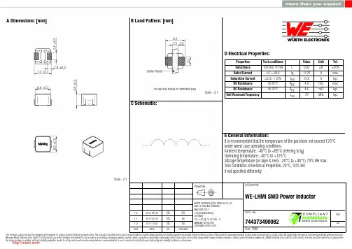
1.2 1.1 1.02012-06-282012-02-292011-10-01SStSStSStSStBDBDWürth Elektronik eiSos GmbH & Co. KGEMC & Inductive SolutionsMax-Eyth-Str. 174638 WaldenburgGermanyTel. +49 (0) 79 42 945 - 0A Dimensions: [mm]F Typical Inductance vs. Current Characteristics: F Typical Temperature rise vs. Current Characteristics:H1: Classification Reflow Profile for SMT components:H2: Classification Reflow ProfilesProfile FeaturePreheat- Temperature Min (T smin ) - Temperature Max (T smax ) - Time (t s ) from (T smin to T smax )Ramp-up rate (T L to T P )Liquidous temperature (T L )Time (t L ) maintained above T L Peak package body temperature (T p )Time within 5°C of actual peak temperature (t p )Ramp-down rate (T P to T L )Time 25°C to peak temperature Pb-Free Assembly 150°C 200°C60-180 seconds 3°C/ second max.217°C60-150 seconds See Table H320-30 seconds 6°C/ second max.8 minutes max.refer to IPC/JEDEC J-STD-020DH3: Package Classification Reflow TemperaturePB-Free Assembly PB-Free Assembly PB-Free Assembly Package Thickness< 1.6 mm 1.6 - 2.5 mm ≥ 2.5 mmVolume mm³<350260°C 260°C 250°CVolume mm³350 - 2000260°C 250°C 245°CVolume mm³>2000260°C 245°C 245°Crefer to IPC/JEDEC J-STD-020DH Soldering Specifications:I Cautions and Warnings:The following conditions apply to all goods within the product series of WE-LHMIof Würth Elektronik eiSos GmbH & Co. KG:General:All recommendations according to the general technical specifications of the data-sheet have to be complied with.The disposal and operation of the product within ambient conditions which probably alloy or harm the wire isolation has to be avoided.If the product is potted in customer applications, the potting material might shrink during and after hardening. Accordingly to this the product is exposed to the pressure of the potting material with the effect that the core, wire and termination is possibly damaged by this pressure and so the electrical as well as the mechanical characteristics are endanger to be affected. After the potting material is cured, the core, wire and termination of the product have to be checked if any reduced electrical or mechanical functions or destructions have occurred.The responsibility for the applicability of customer specific products and use in a particular customer design is always within the authority of the customer. All technical specifications for standard products do also apply for customer specific products.Washing varnish agent that is used during the production to clean the application might damage or change the characteristics of the wire in-sulation, the marking or the plating. The washing varnish agent could have a negative effect on the long turn function of the product.Direct mechanical impact to the product shall be prevented as the iron powder material of the core could flake or in the worst case it could break.Product specific:Follow all instructions mentioned in the datasheet, especially:•The solder profile has to be complied with according to the technical reflow soldering specification, otherwise no warranty will be sustai-ned.•All products are supposed to be used before the end of the period of 12 months based on the product date-code, if not a 100% solderabi-lity can´t be warranted.•Violation of the technical product specifications such as exceeding the nominal rated current will result in the loss of warranty.1. General Customer ResponsibilitySome goods within the product range of Würth Elektronik eiSos GmbH & Co. KG contain statements regarding general suitability for certain application areas. These statements about suitability are based on our knowledge and experience of typical requirements concerning the are-as, serve as general guidance and cannot be estimated as binding statements about the suitability for a customer application. The responsibi-lity for the applicability and use in a particular customer design is always solely within the authority of the customer. Due to this fact it is up to the customer to evaluate, where appropriate to investigate and decide whether the device with the specific product characteristics described in the product specification is valid and suitable for the respective customer application or not.2. Customer Responsibility related to Specific, in particular Safety-Relevant ApplicationsIt has to be clearly pointed out that the possibility of a malfunction of electronic components or failure before the end of the usual lifetime can-not be completely eliminated in the current state of the art, even if the products are operated within the range of the specifications.In certain customer applications requiring a very high level of safety and especially in customer applications in which the malfunction or failure of an electronic component could endanger human life or health it must be ensured by most advanced technological aid of suitable design of the customer application that no injury or damage is caused to third parties in the event of malfunction or failure of an electronic component.3. Best Care and AttentionAny product-specific notes, warnings and cautions must be strictly observed.4. Customer Support for Product SpecificationsSome products within the product range may contain substances which are subject to restrictions in certain jurisdictions in order to serve spe-cific technical requirements. Necessary information is available on request. In this case the field sales engineer or the internal sales person in charge should be contacted who will be happy to support in this matter.5. Product R&DDue to constant product improvement product specifications may change from time to time. As a standard reporting procedure of the Product Change Notification (PCN) according to the JEDEC-Standard inform about minor and major changes. In case of further queries regarding the PCN, the field sales engineer or the internal sales person in charge should be contacted. The basic responsibility of the customer as per Secti-on 1 and 2 remains unaffected.6. Product Life CycleDue to technical progress and economical evaluation we also reserve the right to discontinue production and delivery of products. As a stan-dard reporting procedure of the Product Termination Notification (PTN) according to the JEDEC-Standard we will inform at an early stage about inevitable product discontinuance. According to this we cannot guarantee that all products within our product range will always be available. Therefore it needs to be verified with the field sales engineer or the internal sales person in charge about the current product availability ex-pectancy before or when the product for application design-in disposal is considered.The approach named above does not apply in the case of individual agreements deviating from the foregoing for customer-specific products.7. Property RightsAll the rights for contractual products produced by Würth Elektronik eiSos GmbH & Co. KG on the basis of ideas, development contracts as well as models or templates that are subject to copyright, patent or commercial protection supplied to the customer will remain with Würth Elektronik eiSos GmbH & Co. KG.8. General Terms and ConditionsUnless otherwise agreed in individual contracts, all orders are subject to the current version of the “General Terms and Conditions of Würth Elektronik eiSos Group”, last version available at .J Important Notes:The following conditions apply to all goods within the product range of Würth Elektronik eiSos GmbH & Co. KG:分销商库存信息: WURTH-ELECTRONICS 744373490082。
744765140A;中文规格书,Datasheet资料
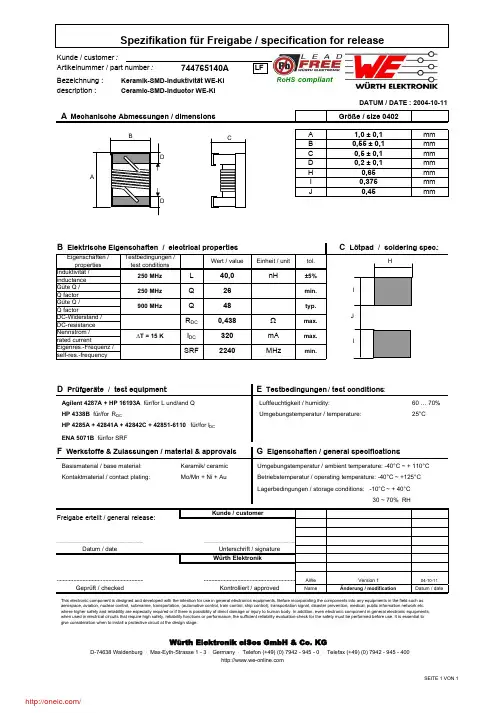
Bezeichnung :description :Größe / size 0402A1,0 ± 0,1mm B 0,55 ± 0,1mm C 0,5 ± 0,1mm D 0,2 ± 0,1mm H 0,65mm I 0,375mm J0,45mm60 … 70%25°CKeramik/ ceramic AWe Version 104-10-11NameÄnderung / modificationDatum / dateENA 5071B für/for SRFD Prüfgeräte / test equipment :Agilent 4287A + HP 16193A für/for L und/and Q HP 4338B für/for R DCHP 4285A + 42841A + 42842C + 42851-6110 für/for I DC A Mechanische Abmessungen / dimensions :Kunde / customer :744765140AKeramik-SMD-Induktivität WE-KI Ceramic-SMD-Inductor WE-KIArtikelnummer / part number :Würth Elektronik eiSos GmbH & Co. KGD-74638 Waldenburg · Max-Eyth-Strasse 1 - 3 · Germany · Telefon (+49) (0) 7942 - 945 - 0 · Telefax (+49) (0) 7942 - 945 - 400Geprüft / checked Betriebstemperatur / operating temperature: -40°C ~ +125°C ......................................................................................................................................................................................................Würth ElektronikSpezifikation für Freigabe / specification for releaseDATUM / DATE : 2004-10-11Datum / date.............................................................................Unterschrift / signatureKontrolliert / approvedG Eigenschaften / general specifications :Lagerbedingungen / storage conditions: -10°C ~ + 40°C 30 ~ 70% RHF Werkstoffe & Zulassungen / material & approvalsKontaktmaterial / contact plating:Mo/Mn + Ni + AuBasismaterial / base material:Kunde / customerFreigabe erteilt / general release:E Testbedingungen / test conditions :Umgebungstemperatur / ambient temperature: -40°C ~ + 110°C Luftfeuchtigkeit / humidity:Umgebungstemperatur / temperature:This electronic component is designed and developed with the intention for use in general electronics equipments. Before incorporating the components into any equipments in the field such as aerospace, aviation, nuclear control, submarine, transportation, (automotive control, train control, ship control), transportation signal, disaster prevention, medical, public information network etc. where higher safety and reliability are especially required or if there is possibility of direct damage or injury to human body. In addition, even electronic component in general electronic equipments, when used in electrical circuits that require high safety, reliability functions or performance, the sufficient reliability evaluation-check for the safety must be performed before use. It is essential to give consideration when to install a protective circuit at the design stage.RoHS compliantLFSEITE 1 VON 1/分销商库存信息: WURTH-ELECTRONICS 744765140A。
GBPC3506W;GBPC3502;GBPC3510W;GBPC3510;GBPC1506;中文规格书,Datasheet资料

The following includes registered and unregistered trademarks and service marks, owned by Fairchild Semiconductor and/or its global subsidiaries, and is notAccuPower¥Auto-SPM¥Build it Now¥CorePLUS¥CorePOWER¥CROSSVOLT¥CTL¥Current Transfer Logic¥DEUXPEED®Dual Cool™ EcoSPARK®EfficientMax¥ESBC¥®Fairchild®Fairchild Semiconductor®FACT Quiet Series¥FACT®FAST®FastvCore¥FETBench¥FlashWriter®*FPS¥F-PFS¥FRFET®Global Power Resource SMGreen FPS¥Green FPS¥ e-Series¥G max¥GTO¥IntelliMAX¥ISOPLANAR¥MegaBuck¥MICROCOUPLER¥MicroFET¥MicroPak¥MicroPak2¥MillerDrive¥MotionMax¥Motion-SPM¥OptoHiT™OPTOLOGIC®OPTOPLANAR®®PDP SPM™Power-SPM¥PowerTrench®PowerXS™Programmable Active Droop¥QFET®QS¥Quiet Series¥RapidConfigure¥¥Saving our world, 1mW/W/kW at a time™SignalWise¥SmartMax¥SMART START¥SPM®STEALTH¥SuperFET¥SuperSOT¥-3SuperSOT¥-6SuperSOT¥-8SupreMOS®SyncFET¥Sync-Lock™®*The Power Franchise®TinyBoost¥TinyBuck¥TinyCalc¥TinyLogic®TINYOPTO¥TinyPower¥TinyPWM¥TinyWire¥TriFault Detect¥TRUECURRENT¥*P SerDes¥UHC®Ultra FRFET¥UniFET¥VCX¥VisualMax¥XS™* Trademarks of System General Corporation, used under license by Fairchild Semiconductor.DISCLAIMERFAIRCHILD SEMICONDUCTOR RESERVES THE RIGHT TO MAKE CHANGES WITHOUT FURTHER NOTICE TO ANY PRODUCTS HEREIN TO IMPROVE RELIABILITY, FUNCTION, OR DESIGN. FAIRCHILD DOES NOT ASSUME ANY LIABILITY ARISING OUT OF THE APPLICATION OR USE OF ANY PRODUCT OR CIRCUIT DESCRIBED HEREIN; NEITHER DOES IT CONVEY ANY LICENSE UNDER ITS PATENT RIGHTS, NOR THE RIGHTS OF OTHERS. THESE SPECIFICATIONS DO NOT EXPAND THE TERMS OF FAIRCHILD’S WORLDWIDE TERMS AND CONDITIONS, SPECIFICALLY THE WARRANTY THEREIN, WHICH COVERS THESE PRODUCTS.LIFE SUPPORT POLICYFAIRCHILD’S PRODUCTS ARE NOT AUTHORIZED FOR USE AS CRITICAL COMPONENTS IN LIFE SUPPORT DEVICES OR SYSTEMS WITHOUT THE EXPRESS WRITTEN APPROVAL OF FAIRCHILD SEMICONDUCTOR CORPORATION.As used herein:1. Life support devices or systems are devices or systems which, (a) areintended for surgical implant into the body or (b) support or sustain life,a nd (c) whose fa ilure to perform when properly used in a ccorda ncewith instructions for use provided in the la beling, ca n be rea sona bly expected to result in a significant injury of the user. 2. A critical component in any component of a life support, device, orsystem whose fa ilure to perform ca n be rea sona bly expected to cause the failure of the life support device or system, or to affect its safety or effectiveness.ANTI-COUNTERFEITING POLICYFairchild Semiconductor Corporation's Anti-Counterfeiting Policy. Fairchild's Anti-Counterfeiting Policy is also stated on our external website, , under Sales Support.Counterfeiting of semiconductor parts is a growing problem in the industry. All manufacturers of semiconductor products are experiencing counterfeiting of their parts. Customers who inadvertently purchase counterfeit parts experience many problems such as loss of brand reputation, substandard performance, failed applications, and increased cost of production and manufacturing delays. Fairchild is taking strong measures to protect ourselves and our customers from the proliferation of counterfeit parts. Fairchild strongly encourages customers to purchase Fairchild parts either directly from Fairchild or from Authorized Fairchild Distributors who are listed by country on our web page cited above. Products customers buy either from Fairchild directly or from Authorized Fairchild Distributors are genuine parts, have full traceability, meet Fairchild's quality standards for handling and storage and provide access to Fairchild's full range of up-to-date technical and product information. Fairchild and our Authorized Distributors will stand behind all warranties and will appropriately address any warranty issues that may arise. Fairchild will not provide any warranty coverage or other assistance for parts bought from Unauthorized Sources. Fairchild is committed to combat this global problem and encourage our customers to do their part in stopping this practice by buying direct or from authorized distributors.PRODUCT STATUS DEFINITIONSDefinition of TermsDatasheet Identification Product Status Definition分销商库存信息:FAIRCHILDGBPC3506W GBPC3502GBPC3510W GBPC3510GBPC1506GBPC2502 GBPC2506GBPC3504GBPC12005 GBPC1202W GBPC1202GBPC1210 GBPC1201GBPC1204W GBPC1206W GBPC1210W GBPC1206GBPC1208 GBPC1204GBPC1201W GBPC15005 GBPC1501GBPC1510W GBPC1506W GBPC1501W GBPC1504W GBPC1510 GBPC1508GBPC1502W GBPC1502 GBPC1508W GBPC1504GBPC15005W GBPC2501GBPC2508GBPC25005 GBPC2504GBPC3504W GBPC3508W GBPC3501W GBPC35005W GBPC3502W GBPC2510GBPC3508GBPC3501 GBPC35005GBPC3506GBPC2501W GBPC2502W GBPC25005W GBPC2508W GBPC2506W GBPC2510W。
7443320470;中文规格书,Datasheet资料

Bezeichnung :description :33%Umgebungstemperatur / temperature:+20°CFerriteLagertemp. / storage temperature: -40°C - +60°C BD09-11-03Rst 09-05-05NameDatum / dateÄnderung / modificationVersion 1Version 2Luftfeuchtigkeit / humidity:It is recommended that the temperature of the part does HP 34401 A & Fluke 54II für/for I DC; SPEICHERDROSSEL WE-HCC 1210 (Ferrit)POWER-CHOKE WE-HCC 1210 (Ferrite)Artikelnummer / part number :7443320470D-74638 Waldenburg · Max-Eyth-Strasse 1 - 3 · Germany · Telefon (+49) (0) 7942 - 945 - 0 · Telefax (+49) (0) 7942 - 945 - 400Geprüft / checked .................................................................................................Basismaterial / base material:Metra HIT 27I für/for R DCArbeitstemperatur / operating temperature: -40°C - +125°C WAYNE KERR 3260B für/for L 0; I SAT D Prüfgeräte / test equipment:E Testbedingungen / test conditions:Kunde / customerF Werkstoffe & Zulassungen / material & approvals:G Eigenschaften / general specifications:not exceed 125°C under worst case operating conditions.Draht / wire:JIS 155°C , UL : E201757Würth Elektronik..................................................................................Freigabe erteilt / general release:http://www.we-online.deDatum / date.............................................................................Unterschrift / signatureKontrolliert / approvedWürth Elektronik eiSos GmbH & Co. KGdatecode & part numberBezeichnung :description :H Induktivitätskurve / Inductance curve:BD09-11-03Rst 09-05-05NameDatum / dateSPEICHERDROSSEL WE-HCC 1210 (Ferrit)POWER-CHOKE WE-HCC 1210 (Ferrite)DATUM / DATE : 2009-11-03Freigabe erteilt / general release:Kunde / customer...............................................................................................................................................................Datum / dateUnterschrift / signature Würth ElektronikVersion 2..........................................................................................................................................Version 1D-74638 Waldenburg · Max-Eyth-Strasse 1 - 3 · Germany · Telefon (+49) (0) 7942 - 945 - 0 · Telefax (+49) (0) 7942 - 945 - 400http://www.we-online.deGeprüft / checked Kontrolliert / approvedÄnderung / modificationWürth Elektronik eiSos GmbH & Co. KGBezeichnung :description :I Temperaturanstieg / Temperature rise curve:BD09-11-03Rst 09-05-05NameDatum / dateDATUM / DATE : 2009-11-03Version 1D-74638 Waldenburg · Max-Eyth-Strasse 1 - 3 · Germany · Telefon (+49) (0) 7942 - 945 - 0 · Telefax (+49) (0) 7942 - 945 - 400...............................................................................................................................................................Datum / dateUnterschrift / signaturehttp://www.we-online.deGeprüft / checked Kontrolliert / approvedÄnderung / modificationWürth Elektronik eiSos GmbH & Co. KGSPEICHERDROSSEL WE-HCC 1210 (Ferrit)POWER-CHOKE WE-HCC 1210 (Ferrite)Freigabe erteilt / general release:Kunde / customerWürth ElektronikVersion 2..........................................................................................................................................Bezeichnung :description :BD09-11-03Rst 09-05-05NameDatum / dateSPEICHERDROSSEL WE-HCC 1210 (Ferrit)POWER-CHOKE WE-HCC 1210 (Ferrite)Freigabe erteilt / general release:Kunde / customer...............................................................................................................................................................Datum / dateUnterschrift / signature Würth ElektronikVersion 2............................................................................................................................................Version 1D-74638 Waldenburg · Max-Eyth-Strasse 1 - 3 · Germany · Telefon (+49) (0) 7942 - 945 - 0 · Telefax (+49) (0) 7942 - 945 - 400Geprüft / checked Kontrolliert / approvedÄnderung / modificationWürth Elektronik eiSos GmbH & Co. KGThe Force for tearing off cover tape is 20 to 70 grams in arrow direction150°feeding directionThis electronic component has been designed and developed for usage in general electronic equipment. Before incorporating this component into any equipment where higher safety and reliability is especially required or if there is the possibility of direct damage or injury to human body, for example in the range of aerospace, aviation, nuclear control, submarine, transportation, (automotive control, train control, ship control), transportation signal, disaster prevention, medical, public information network etc, Würth Elektronik eiSos GmbH must be informed before the design-in stage. In addition, sufficient reliability evaluation checks for safety must be performed on every electronic component which is used in electrical circuits that require high safety and reliability functions or performance.分销商库存信息: WURTH-ELECTRONICS 7443320470。
74489430056;中文规格书,Datasheet资料
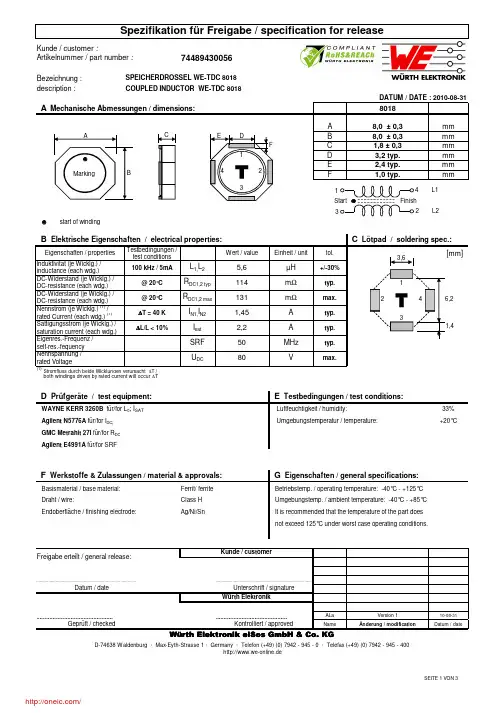
Bezeichnung :description :A mmB mmC mmD mmE mm Fmmstart of windingEigenschaften / propertiesWert / valueEinheit / unittol.Induktivität (je Wicklg.) /inductance (each wdg.)DC-Widerstand (je Wicklg.) /DC-resistance (each wdg.)DC-Widerstand (je Wicklg.) /DC-resistance (each wdg.)Nennstrom (je Wicklg.) (1) /rated Current (each wdg.) (1)Sättigungsstrom (je Wicklg.) /saturation current (each wdg.)Eigenres.-Frequenz /self-res.-fequency Nennspannung /rated Voltage (1)Stromfluss durch beide Wicklungen verursacht ∆T /both windings driven by rated current will occur ∆T33% Umgebungstemperatur / temperature:+20°CFerrit/ ferrite ALa 10-08-31NameDatum / dateI sat A SRF MHz ∆T = 40 K typ.typ.I N1,I N2m Ω@ 20°Cm Ωtyp.2,2typ.SPEICHERDROSSEL WE-TDC 8018COUPLED INDUCTOR WE-TDC 8018µH R DC1,2 max L 1,L 2 A Mechanische Abmessungen / dimensions:100 kHz / 5mAR DC1,2 typ 114Endoberfläche / finishing electrode:Ag/Ni/SnC Lötpad / soldering spec.:B Elektrische Eigenschaften / electrical properties:Umgebungstemp. / ambient temperature: -40°C - +85°C 50Geprüft / checked DATUM / DATE : 2010-08-31max.Testbedingungen / test conditions131+/-30%Freigabe erteilt / general release:http://www.we-online.deDatum / date..................................................................................Unterschrift / signatureKontrolliert / approvedWürth Elektronik eiSos GmbH & Co. KGD-74638 Waldenburg · Max-Eyth-Strasse 1 · Germany · Telefon (+49) (0) 7942 - 945 - 0 · Telefax (+49) (0) 7942 - 945 - 400GMC Metrahit 27I für/for R DC Agilent E4991A für/for SRFnot exceed 125°C under worst case operating conditions.Würth Elektronik..................................................................................Agilent N5776A für/for I DC;WAYNE KERR 3260B für/for L 0; I SAT D Prüfgeräte / test equipment:@ 20°CKunde / customerLuftfeuchtigkeit / humidity:E Testbedingungen / test conditions:8,0 ± 0,3It is recommended that the temperature of the part does F Werkstoffe & Zulassungen / material & approvals:G Eigenschaften / general specifications:Betriebstemp. / operating temperature: -40°C - +125°C ...........................................................................................Basismaterial / base material:Draht / wire:Class H 1,8 ± 0,38,0 ± 0,33,2 typ.2,4 typ.1,0 typ.8018Änderung / modificationVersion 1U DC80Vmax.1,45A 5,6∆L/L < 10%[mm]CABMarking DE F134 L12 L2Start Finish12346,23,61,41432description :ALa 10-08-31NameDatum / dateWürth Elektronik eiSos GmbH & Co. KGD-74638 Waldenburg · Max-Eyth-Strasse 1 · Germany · Telefon (+49) (0) 7942 - 945 - 0 · Telefax (+49) (0) 7942 - 945 - 400Änderung / modificationhttp://www.we-online.de...........................................................................................Geprüft / checked Kontrolliert / approvedVersion 1Datum / dateUnterschrift / signature Würth ElektronikFreigabe erteilt / general release:Kunde / customer....................................................................................................................................................................COUPLED INDUCTOR WE-TDC 8018DATUM / DATE : 2010-08-31H Induktivitätskurve / Inductance curve:0,001,002,003,004,005,006,000,000,501,001,502,002,503,003,504,00L (µH )Current (A)Induktivität vs Strom (typ.)/ Inductance vs Current (typ.)description :I Rollenspezifikation / tape and reel specification:A 8,4± 0,1mmB 16,0± 0,3mmC 1,5+ 0,1mmD 4,0± 0,1mmE 2,0± 0,1mmF 7,5± 0,1mmG 12,0± 0,1mmH 2,0± 0,1mmI 0,3± 0,05mmRollenspezifikation / Reel specification:a 178,0± 2,0mmb 21,00± 0,8mmc 13,00± 0,5mmd 50,00± 1,0mmALa 10-08-31NameDatum / dateGurtspezifikation / Tape specification:Unterschrift / signature Würth Elektronik eiSos GmbH & Co. KGD-74638 Waldenburg · Max-Eyth-Strasse 1 · Germany · Telefon (+49) (0) 7942 - 945 - 0 · Telefax (+49) (0) 7942 - 945 - 400Freigabe erteilt / general release:Kunde / customer....................................................................................................................................................................Änderung / modificationhttp://www.we-online.de...........................................................................................Geprüft / checked Kontrolliert / approvedDatum / dateWürth ElektronikCOUPLED INDUCTOR WE-TDC 8018DATUM / DATE : 2010-08-31Version 1no component / 160 mm min.componentsno components / 100 mm min.EndStartfeedingdirectionDGBØ cadbThis electronic component has been designed and developed for usage in general electronic equipment. Before incorporating this component into any equipment where higher safety and reliability is especially required or if there is the possibility of direct damage or injury to human body, for example in the range of aerospace, aviation, nuclear control, submarine, transportation, (automotive control, train control, ship control), transportation signal, disaster prevention, medical, public information network etc, Würth Elektronik eiSos GmbH must be informed before the design-in stage. In addition, sufficient reliability evaluation checks for safety must be performed on every electronic component which is used in electrical circuits that require high safety and reliability functions or performance.XXX XXXcover tapeEA øCFHI A400 mm min .分销商库存信息: WURTH-ELECTRONICS 74489430056。
74437324068;中文规格书,Datasheet资料
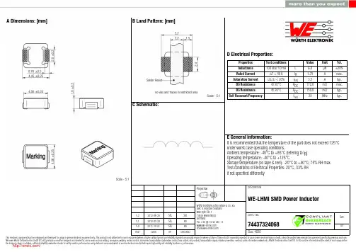
1.2 1.1 1.02012-06-282012-02-292011-10-01SStSStSStSStBDBDWürth Elektronik eiSos GmbH & Co. KGEMC & Inductive SolutionsMax-Eyth-Str. 174638 WaldenburgGermanyTel. +49 (0) 79 42 945 - 0A Dimensions: [mm]F Typical Inductance vs. Current Characteristics: F Typical Temperature rise vs. Current Characteristics:H1: Classification Reflow Profile for SMT components:H2: Classification Reflow ProfilesProfile FeaturePreheat- Temperature Min (T smin ) - Temperature Max (T smax ) - Time (t s ) from (T smin to T smax )Ramp-up rate (T L to T P )Liquidous temperature (T L )Time (t L ) maintained above T L Peak package body temperature (T p )Time within 5°C of actual peak temperature (t p )Ramp-down rate (T P to T L )Time 25°C to peak temperature Pb-Free Assembly 150°C 200°C60-180 seconds 3°C/ second max.217°C60-150 seconds See Table H320-30 seconds 6°C/ second max.8 minutes max.refer to IPC/JEDEC J-STD-020DH3: Package Classification Reflow TemperaturePB-Free Assembly PB-Free Assembly PB-Free Assembly Package Thickness< 1.6 mm 1.6 - 2.5 mm ≥ 2.5 mmVolume mm³<350260°C 260°C 250°CVolume mm³350 - 2000260°C 250°C 245°CVolume mm³>2000260°C 245°C 245°Crefer to IPC/JEDEC J-STD-020DH Soldering Specifications:I Cautions and Warnings:The following conditions apply to all goods within the product series of WE-LHMIof Würth Elektronik eiSos GmbH & Co. KG:General:All recommendations according to the general technical specifications of the data-sheet have to be complied with.The disposal and operation of the product within ambient conditions which probably alloy or harm the wire isolation has to be avoided.If the product is potted in customer applications, the potting material might shrink during and after hardening. Accordingly to this the product is exposed to the pressure of the potting material with the effect that the core, wire and termination is possibly damaged by this pressure and so the electrical as well as the mechanical characteristics are endanger to be affected. After the potting material is cured, the core, wire and termination of the product have to be checked if any reduced electrical or mechanical functions or destructions have occurred.The responsibility for the applicability of customer specific products and use in a particular customer design is always within the authority of the customer. All technical specifications for standard products do also apply for customer specific products.Washing varnish agent that is used during the production to clean the application might damage or change the characteristics of the wire in-sulation, the marking or the plating. The washing varnish agent could have a negative effect on the long turn function of the product.Direct mechanical impact to the product shall be prevented as the iron powder material of the core could flake or in the worst case it could break.Product specific:Follow all instructions mentioned in the datasheet, especially:•The solder profile has to be complied with according to the technical reflow soldering specification, otherwise no warranty will be sustai-ned.•All products are supposed to be used before the end of the period of 12 months based on the product date-code, if not a 100% solderabi-lity can´t be warranted.•Violation of the technical product specifications such as exceeding the nominal rated current will result in the loss of warranty.1. General Customer ResponsibilitySome goods within the product range of Würth Elektronik eiSos GmbH & Co. KG contain statements regarding general suitability for certain application areas. These statements about suitability are based on our knowledge and experience of typical requirements concerning the are-as, serve as general guidance and cannot be estimated as binding statements about the suitability for a customer application. The responsibi-lity for the applicability and use in a particular customer design is always solely within the authority of the customer. Due to this fact it is up to the customer to evaluate, where appropriate to investigate and decide whether the device with the specific product characteristics described in the product specification is valid and suitable for the respective customer application or not.2. Customer Responsibility related to Specific, in particular Safety-Relevant ApplicationsIt has to be clearly pointed out that the possibility of a malfunction of electronic components or failure before the end of the usual lifetime can-not be completely eliminated in the current state of the art, even if the products are operated within the range of the specifications.In certain customer applications requiring a very high level of safety and especially in customer applications in which the malfunction or failure of an electronic component could endanger human life or health it must be ensured by most advanced technological aid of suitable design of the customer application that no injury or damage is caused to third parties in the event of malfunction or failure of an electronic component.3. Best Care and AttentionAny product-specific notes, warnings and cautions must be strictly observed.4. Customer Support for Product SpecificationsSome products within the product range may contain substances which are subject to restrictions in certain jurisdictions in order to serve spe-cific technical requirements. Necessary information is available on request. In this case the field sales engineer or the internal sales person in charge should be contacted who will be happy to support in this matter.5. Product R&DDue to constant product improvement product specifications may change from time to time. As a standard reporting procedure of the Product Change Notification (PCN) according to the JEDEC-Standard inform about minor and major changes. In case of further queries regarding the PCN, the field sales engineer or the internal sales person in charge should be contacted. The basic responsibility of the customer as per Secti-on 1 and 2 remains unaffected.6. Product Life CycleDue to technical progress and economical evaluation we also reserve the right to discontinue production and delivery of products. As a stan-dard reporting procedure of the Product Termination Notification (PTN) according to the JEDEC-Standard we will inform at an early stage about inevitable product discontinuance. According to this we cannot guarantee that all products within our product range will always be available. Therefore it needs to be verified with the field sales engineer or the internal sales person in charge about the current product availability ex-pectancy before or when the product for application design-in disposal is considered.The approach named above does not apply in the case of individual agreements deviating from the foregoing for customer-specific products.7. Property RightsAll the rights for contractual products produced by Würth Elektronik eiSos GmbH & Co. KG on the basis of ideas, development contracts as well as models or templates that are subject to copyright, patent or commercial protection supplied to the customer will remain with Würth Elektronik eiSos GmbH & Co. KG.8. General Terms and ConditionsUnless otherwise agreed in individual contracts, all orders are subject to the current version of the “General Terms and Conditions of Würth Elektronik eiSos Group”, last version available at .J Important Notes:The following conditions apply to all goods within the product range of Würth Elektronik eiSos GmbH & Co. KG:分销商库存信息: WURTH-ELECTRONICS 74437324068。
74456147;中文规格书,Datasheet资料
description :=Marking33% Umgebungstemperatur / temperature:+20°CSSt2006-09-27MST 2004-10-11NameDatum / dateHP 34401 A für/for I DC und/and R DCLuftfeuchtigkeit / humidity:HP 4274 A für/for L und/and Q Betriebstemp. / operating temperature: -40°C - + 125°C Sockel / BaseUL94-V0Anbindung an Elektrode / soldering wire to platingSn/Cu - 97/3%Endoberfläche / finishing electrode100% Sn Datum / date...........................................................................Unterschrift / signature Kontrolliert / approvedWürth Elektronik eiSos GmbH & Co. KGD-74638 Waldenburg · Max-Eyth-Strasse 1 - 3 · Germany · Telefon (+49) (0) 7942 - 945 - 0 · Telefax (+49) (0) 7942 - 945 - 400Geprüft / checked .......................................................................................................................................It is recommended that the temperature of the part does not exceed 125°C under worst case operating conditions.Umgebungstemp. / ambient temperature: -40°C - + 85°C Basismaterial / base material:Draht / wire:POWER-CHOKE WE-PD 4Ferrit/ferrite 2 UEWF 155°C F Werkstoffe & Zulassungen / material & approvals :G Eigenschaften / general specifications :D Prüfgeräte / test equipment :E Testbedingungen / test conditions :Freigabe erteilt / general release:Kunde / customerWürth Elektronik..................................................................................Änderung / modificationVersion 1Version 2description :SSt2006-09-27MST 2004-10-11NameDatum / datePOWER-CHOKE WE-PD 4....................................................................................................................................................................................................................................................................................................Datum / dateUnterschrift / signatureDATUM / DATE : 2006-09-27H Induktivitätskurve / Inductance curve :Freigabe erteilt / general release:Kunde / customerWürth Elektronik eiSos GmbH & Co. KGD-74638 Waldenburg · Max-Eyth-Strasse 1 - 3 · Germany · Telefon (+49) (0) 7942 - 945 - 0 · Telefax (+49) (0) 7942 - 945 - 400Würth ElektronikGeprüft / checked Kontrolliert / approvedÄnderung / modificationVersion 1Version 2description :SSt2006-09-27MST 2004-10-11NameDatum / dateGeprüft / checked Kontrolliert / approvedWürth Elektronik eiSos GmbH & Co.KGD-74638 Waldenburg · Max-Eyth-Strasse 1 - 3 · Germany · Telefon (+49) (0) 7942 - 945 - 0 · Telefax (+49) (0) 7942 - 945 - 400Würth Elektronik....................................................................................................................................................................................................................................................................................................Datum / dateUnterschrift / signature Freigabe erteilt / general release:Kunde / customerPOWER-CHOKE WE-PD 4Änderung / modificationVersion 1Version 2The force for tearing off cover tape is 20 to 70 grams in arrow direction150°feeding directionThis electronic component has been designed and developed for usage in general electronic equipment. Before incorporating this component into any equipment where higher safety and reliability is especially required or if there is the possibility of direct damage or injury to human body, for example in the range of aerospace, aviation, nuclear control, submarine, transportation, (automotive control, train control, ship control), transportation signal, disaster prevention, medical, public information network etc, Würth Elektronik eiSos GmbH must be informed before the design-in stage. In addition, sufficient reliability evaluation checks for safety must be performed on every electronic component which is used in electrical circuits that require high safety and reliability functions or performance.分销商库存信息: WURTH-ELECTRONICS 74456147。
IR3553MTRPBF;中文规格书,Datasheet资料
FEATURES∙ Peak efficiency up to 93.2% at 1.2V∙ Integrated driver, control MOSFET, synchronous MOSFET and Schottky diode ∙ Input voltage (VIN) operating range up to 15V ∙ Output voltage range from 0.25V up to 3.3V ∙ Output current capability of 40A DC ∙ Operation up to 1.0MHz∙ Integrated current sense amplifier ∙ VCC under voltage lockout ∙ Thermal flag∙ Body-Braking® load transient support ∙ Diode-emulation high efficiency mode∙ Compatible with 3.3V PWM logic and VCC tolerant ∙ Compliant with Intel DrMOS V4.0∙ PCB footprint compatible with IR3550 and IR3551 ∙ Efficient dual sided cooling∙ Small 4mm x 6mm x 0.9mm PQFN package ∙ Lead free RoHS compliant packageAPPLICATIONS∙ Voltage Regulators for CPUs, GPUs, and DDR memory arrays ∙ High current, low profile DC-DC convertersDESCRIPTIONThe IR3553 integrated PowIRstage® is a synchronous buck gate driver co-packed with a control MOSFET and a synchronous MOSFET with integrated Schottky diode. It is optimized internally for PCB layout, heat transfer and driver/MOSFET timing. Custom designed gate driver and MOSFET combination enables higher efficiency at lower output voltages required by cutting edge CPU, GPU and DDR memory designs.Up to 1.0MHz switching frequency enables high performance transient response, allowing miniaturization of output inductors, as well as input and output capacitors while maintaining industry leading efficiency. The IR3553’s superior efficiency enables smallest size and lower solution cost. The IR3553 PCB footprint is compatible with the IR3550 (60A) and the IR3551 (50A).Integrated current sense amplifier achieves superior current sense accuracy and signal to noise ratio vs. best-in-class controller based Inductor DCR sense methods. The IR3553 incorporates the Body- Braking® feature which enables reduction of output capacitors. Synchronous diode emulation mode in the IR3553 removes the zero-current detection burden from the PWM controller and increases system light-load efficiency.The IR3553 is optimized specifically for CPU core power delivery in server applications. The ability to meet the stringent requirements of the server market also makes the IR3553 ideally suited to powering GPU and DDR memory designs and other high current applications.PINOUT DIAGRAMFigure 3: IR3553 Pin Diagram, Top ViewORDERING INFORMATIONTYPICAL APPLICATION DIAGRAMIOUTVCC BBRK#REFINVOUTFigure 4: Application Circuit with Current Sense AmplifierTYPICAL APPLICATION DIAGRAM (CONTINUED)VCC BBRK#VOUTFigure 5: Application Circuit without Current Sense AmplifierFUNCTIONAL BLOCK DIAGRAMPHSFLT#REFINPWM VIN SWSW SW SW SWSW TGND BOOST IOUT VCCBBRK#GATEL CSIN+LGNDPGNDFigure 6: IR3553 Functional Block DiagramPIN DESCRIPTIONSABSOLUTE MAXIMUM RATINGSStresses beyond those listed under “Absolute Maximum Ratings” may cause permanent damage to the device. These are stress ratings only and functional operation of the device at these or any other conditions beyond those indicated in the operational sections of the specifications are not implied.Note:1. Maximum BOOST – SW = 8V.2. Maximum VIN – SW = 25V.3. All the maximum voltage ratings are referenced to PGND (Pins 12 and 13).Note:1. Thermal Resistance (θJA) is measured with the component mounted on a high effective thermal conductivity test board in free air.Refer to International Rectifier Application Note AN-994 for details.ELECTRICAL SPECIFICATIONSThe electrical characteristics involve the spread of values guaranteed within the recommended operating conditions. Typical values represent the median values, which are related to 25°C.RECOMMENDED OPERATING CONDITIONS FOR RELIABLE OPERATION WITH MARGINELECTRICAL CHARACTERISTICSNotes1. Guaranteed by design but not tested in production2.V IN=12V, V OUT=1.2V, ƒSW = 300kHz, L=210nH (0.2mΩ), VCC=6.8V, C IN=47uF x 4, C OUT =470uF x3, 400LFM airflow, no heat sink, 25°Cambient temperature, and 8-layer PCB of 3.7” (L) x 2.6” (W). PWM controller loss and inductor loss are not included.3. V IN=12V, V OUT=1.2V, ƒSW = 400kHz, L=150nH (0.29mΩ), VCC=7V, C IN=47uF x 4, C OUT =470uF x3, no airflow, no heat sink, 25°C ambienttemperature, and 8-layer PCB of 3.7” (L) x 2.6” (W). PWM controller loss and inductor loss are not included.TYPICAL OPERATING CHARACTERISTICSCircuit of Figure 32, V IN =12V, V OUT =1.2V, ƒSW = 400kHz, L=150nH (0.29m Ω), VCC=7V, T AMBIENT = 25°C, no heat sink, no air flow, 8-layer PCB board of 3.7” (L) x 2.6” (W), no PWM controller loss, no inductor loss, unless specified otherwise.TYPICAL OPERATING CHARACTERISTICS (CONTINUED)Circuit of Figure 32, V IN =12V, V OUT =1.2V, ƒSW = 400kHz, L=150nH (0.29m Ω), VCC=7V, T AMBIENT = 25°C, no heat sink, no air flow, 8-layer PCB board of 3.7” (L) x 2.6” (W), no PWM controller loss, no inductor loss, unless specified otherwise.Figure 13: Normalized Power Loss vs. VCC Voltage Figure 14: Power Loss vs. Output Inductor Figure 15: VCC Current vs. Switching FrequencyFigure 16: Switching Waveform, I OUT = 0AFigure 17: Switching Waveform, I OUT = 40AFigure 18: PWM to SW Delays, I OUT = 10APWM 2V/divSW 5V/div40ns/divPWM 5V/divSW 5V/divGATEL 10V/div400ns/divPWM 5V/divSW 5V/divGATEL 10V/div400ns/div分销商库存信息: IRIR3553MTRPBF。
7443资料
ELECTRICAL SPECIFICATIONS @ 25˚C
Center frequency range: . . . . . . . . . . . . . . . . . . . . . . . . . . . . . . . . . . . . . . . . . . . . . . . . . . . . . . . . . . .250 Hz to 10 kHz Bandwidth: . . . . . . . . . . . . . . . . . . . . . . . . . . . . . . . . . . . . . . . . . . . . . . . . . . . . . . . . . . . . . . . . . . .± 30 Hz to ± 250 Hz Input level range: . . . . . . . . . . . . . . . . . . . . . . . . . . . . . . . . . . . . . . . . . . . . . . . . . . . . . . . . . . . . . . . .0.1 V to 3.5 Vrms Input Impedance: . . . . . . . . . . . . . . . . . . . . . . . . . . . . . . . . . . . . . . . . . . . . . . . . . . . . . . . . . . . . . . . . . . . . . . . .200 Ω Output Impedance: . . . . . . . . . . . . . . . . . . . . . . . . . . . . . . . . . . . . . . . . . . . . . . . . . . . . . . . . . . . . . . . . . . . . . .2500 Ω Steepness factor: . . . . . . . . . . . . . . . . . . . . . . . . . . . . . . . . . . . . . . . . . . . . . . . . . . . . . . . . . . . . . . . . . . . . . . . . .5 - 15 Steepness factor is defined as: . . . . . . . . . . . . . . . . . . . . . . . . . . . . . . . . . . . . . . . . . . . . . . . . . . . .Bandwidth at 60 dB Bandwidth at 3 dB Voltage Insulation: . . . . . . . . . . . . . . . . . . . . . . . . . . . . . . . . . . . . . . .750 VDC from input terminals to output terminals Operating temperature: . . . . . . . . . . . . . . . . . . . . . . . . . . . . . . . . . . . . . . . . . . . . . . . . . . . . . . . . . . . . .-20°C to +50°C Storage temperature: . . . . . . . . . . . . . . . . . . . . . . . . . . . . . . . . . . . . . . . . . . . . . . . . . . . . . . . . . . . . . .-40°C to + 80°C
744765039A;中文规格书,Datasheet资料
Bezeichnung :description :Größe / size 0402A1,0 ± 0,1mm B 0,55 ± 0,1mm C 0,5 ± 0,1mm D 0,2 ± 0,1mm H 0,65mm I 0,375mm J0,45mm60 … 70%25°CKeramik/ ceramic AWe Version 104-10-11NameÄnderung / modificationDatum / dateENA 5071B für/for SRFD Prüfgeräte / test equipment :Agilent 4287A + HP 16193A für/for L und/and Q HP 4338B für/for R DCHP 4285A + 42841A + 42842C + 42851-6110 für/for I DC A Mechanische Abmessungen / dimensions :Kunde / customer :744765039AKeramik-SMD-Induktivität WE-KI Ceramic-SMD-Inductor WE-KIArtikelnummer / part number :Würth Elektronik eiSos GmbH & Co. KGD-74638 Waldenburg · Max-Eyth-Strasse 1 - 3 · Germany · Telefon (+49) (0) 7942 - 945 - 0 · Telefax (+49) (0) 7942 - 945 - 400Geprüft / checked Betriebstemperatur / operating temperature: -40°C ~ +125°C ......................................................................................................................................................................................................Würth ElektronikSpezifikation für Freigabe / specification for releaseDATUM / DATE : 2004-10-01Datum / date.............................................................................Unterschrift / signatureKontrolliert / approvedG Eigenschaften / general specifications :Lagerbedingungen / storage conditions: -10°C ~ + 40°C 30 ~ 70% RHF Werkstoffe & Zulassungen / material & approvalsKontaktmaterial / contact plating:Mo/Mn + Ni + AuBasismaterial / base material:Kunde / customerFreigabe erteilt / general release:E Testbedingungen / test conditions :Umgebungstemperatur / ambient temperature: -40°C ~ + 110°C Luftfeuchtigkeit / humidity:Umgebungstemperatur / temperature:This electronic component is designed and developed with the intention for use in general electronics equipments. Before incorporating the components into any equipments in the field such as aerospace, aviation, nuclear control, submarine, transportation, (automotive control, train control, ship control), transportation signal, disaster prevention, medical, public information network etc. where higher safety and reliability are especially required or if there is possibility of direct damage or injury to human body. In addition, even electronic component in general electronic equipments, when used in electrical circuits that require high safety, reliability functions or performance, the sufficient reliability evaluation-check for the safety must be performed before use. It is essential to give consideration when to install a protective circuit at the design stage.RoHS compliantLFSEITE 1 VON 1/分销商库存信息: WURTH-ELECTRONICS 744765039A。