
CBAT产品安装手册
产品安装手册
资料名称:产品安装手册
资料版本:V1.0
编制日期:2012-7
目的本手册用于局端(CBAT)、终端(CNU)产品介绍及安装。
使用对象本手册主要面向客户负责产品安装维护人员。
术语及缩略语定义
CBAT –网络分配器(Coaxial Broadband Access Terminal),即局端设备CNU –用户前端设备(Customer Network Unit),即终端设备
第1章局端(CBAT)设备安装
本章简要介绍了系统简介、硬件组成、设备安装及性能参数
1.1系统简介
CBAT产品是为适应运营商不同的网络环境和业务需求而推出的新一代模块化、基于Homeplug AV和IEEE 802.11n标准的高低频混合型EOC局端产品,支持4路射频模块,可支持2高频2低频,同轴线路2进2出,千兆以太网上连,可选ONU上连模块,适应各种复杂的网络环境。
图1 CBAT网络架构图及系统工作频段
1.2硬件组成
EOC高频局端一体野外型、模块化设计,满配两块高频板卡、两块低频板卡和一块ONU板卡。
尺寸:316*238*162mm,设备如下图所示:
图2 设备内部板卡组成
图3 设备外观及内部结构
产品性能
•基于IEEE 802.11n(高频)和Homeplug AV(低频)标准。
•野外型,模块化设计,可支持1~4个EOC模块扩展。
•支持高低频EOC应用,最大可装配二个低频模块,二个高频模块。
•高带宽,单模块物理层速率最高可达700Mbps(低频)和150Mbps(高频),MAC层
速率最高300Mbps(低频)和100Mbps(高频)。
•集成交换网板设计,千兆上联数据接口,可选内置ONU上联模块。
•占用900MHZ以上频段(高频)和7.5~65MHZ频段(低频),对现有的CATV信号无任何影响。
•支持220V AC和60V AC两种电源供电。
•支持W-View网管统一管理。
1.3设备安装
1.3.1安装流程
CBAT局端设备长期、安全、稳定运行与硬件安装工程的质量有密切关系。
因此需要安装工程系统化、规范化,这样才能有效地减少因安装原因而造成的设备运行的不稳定因素,提高设备在网上运行的可靠性及工作效率。
CBAT局端硬件安装的总体流程如图所示。
-5公制F接头;
1.3.3安装工具准备
1.3.4设备安装
图4 CBAT现场安装示意图
CBAT端口定义及连接
●TV 1-2:同轴电缆公制F-Female头接口。
CATV信号的输入端口,接光接收机输出端口。
●COM1-2:同轴电缆公制F-Female头接口。
混合信号输出端口,下一级用户网络。
●AUX:10/100Base-T Ethernet网络端口。
管理低频PLC模块。
●ETH:10/100Base-T Ethernet网络端口。
本地高频WOC模块管理口,以太网上联口。
●PON:尾纤输入口。
连接光线路终端盒。
注意事项
根据要求在多媒体箱中整齐安装,走线规范、美观。
设备接头为‐5公制F头,一般采用‐5跳线进行连接,当接‐7/‐9/‐12线缆时需使用转接头转换为‐5公制F头,或通过‐5线转接,否则会将会损坏设备接头,有线电视信号插入损耗过大,导致电视无法正常收看。
在安装60V设备时,应先连接其他电缆,最后连接60V供电线缆,严禁带电操作。
局端安装后需粘贴设备标签,标签的信息包括:IP地址、安装位置等信息;同时记录高频、低频IP地址、MAC地址、安装位置,ONU MAC地址。
为了增加防雷性能,局端设备外壳需要良好接地;供局端设备工作的电源应保持良好接地。
1.4技术参数
第2章高频终端(CNU)
本章介绍高频终端(CNU)安装准备、及安装过程
2.1系统简介
BIOC(Broadcasting and Interactivity Over Cable)广播交互同轴网络接入技术是针对HFC 网络光节点后最后1公里的双向接入解决方案,该技术充分利用了成熟的WiFi(802.11n),通过降频把WiFi信号的频率降低到更适合cable传输的950~1050MHz频段,和接入网技术必需的虚拟二层交换机的思路,利用原有的分配网资源承载广播电视信号(模拟/数字电视)与数据信号,是将基带数据信号经数字调制到合适的射频频段,与电视信号混合,通过同轴电缆传输到用户,在用户端将电视信号和数据信号分离后,在采用对应的解调技术,把调制数据信号还原为基带数据信号。
2.2 高频终端
2.2.1硬件介绍
高频终端产品是BIOC技术与机顶盒STB结合的终端产品,充分利用目前交互机顶盒高速的、标准的接口USB接口和机顶盒其他系统资源,在不降低EoC网络通信能力和机顶盒正常工作性能的前提下,以很低的价格实现高速的双向通信,大幅降低了广电运营商双向网络改造成本。
产品性能
•符合IEEE 801.11n标准
•高带宽,速率最高可达100Mbps
•低成本,高度集成核心芯片,户均成本仅为其他技术的1/2左右
•通过USB接口,实现数据通讯和供电
•完全开放的思路进行产品设计和开发,系统具有良好的开放性和兼容性
•不改变现有机顶盒的体系架构,只需简单移植相应的终端驱动程序即可
•与业务无关,不会限制任何新业务、新产品的开发
•上/下行限速,带宽可控
•支持W-View网管统一管理
2.2.2设备安装
安装准备
开通用户线路,首先因具备以下几个基本条件:
(1)高频:CNU终端接收的信号强调RSSI值≥15,且CNU终端接收(T-RSSI)和发送(R-RSSI)信号之间的差值小于15。
(2)HFC网络中分支分配器支持5M-1GHz信号。
(3)用户室内无自行安装的放大器。
设备连接
(1)端口定义
RF IN:同轴电缆英制F-Female头接口。
混合信号的输入端口,上联CBAT设备。
RF OUT:同轴电缆英制F-Female头接口。
CATV信号输出端口,接用户电视或机顶盒的RF 端口。
Mini USB口:USB2.0端口。
连接机顶盒的USB接口。
RF IN射频口:终端IP和TV混合信号引入接口,与用户家中的有线电视分线盒相连。
射频口:终端TV信号输出接口,与机顶盒的RF IN口相连。
口:终端IP信号输出接口,与机顶盒的USB口相连。
2.2.3技术参数
第3章低频终端(CNU)
本章介绍低频终端(CNU)安装准备、及安装过程
3.1系统简介
Home Plug AV标准是由电力线通信技术领域的权威国际机构——家庭插电联盟制定。
HomePlug AV技术在物理层采用具有高级前向纠错、通道预估和自适应能力的OFDM,而在MAC层则综合使用具有QoS保证的TDMA时分多址有序接入和CSMA竞争接入两种方式,并通过快速自动重发请求(ARQ)来保障可靠传送,正因为其高带宽、抗干扰能力强等优势成为众多低频EoC产品技术的首选。
3.2 低频终端
3.2.1硬件介绍
低频终端产品是为适应运营商高带宽业务需求而推出的新一代低频EOC终端产品,本地提供4个百兆全双工以太网接口,可用于同时连接计算机、数字电视机顶盒、IP电话机等多种终端,满足用户多业务接入和交互电视业务的需求。
产品性能
•符合HomePlug AV(IEEE P1901)标准
•提供4个10/100M自适应以太网接口
•两路RF接口,用于混合信号输入、TV信号输出
•支持基于端口或基于802.1Q的VLAN端口配置
•支持QoS策略,为不同业务类型的数据流提供不同传输保障
•上/下行限速,带宽可控
•占用35MHz以下的低频带通信,对现有的CATV信号无任何影响
•无需用户配置,方便开通
•支持W-View网管统一管理
安装准备开通用户线路,首先因具备以下几个基本条件:
(1)线路衰减≤95dB(7.5~35MHZ)。
(2)用户室内无自行安装的放大器。
11
(3)终端各指示灯正常:CABLE灯和PC、STB、ETH灯闪烁。
设备连接
图8 低频终端
(1)端口定义
•Cable:同轴电缆F-Female头接口。
混合信号的输入端口,接家中有线电视插口。
•TV:同轴电缆F-Female头接口。
CATV信号输出端口,接用户电视或机顶盒的RF端口。
•PC、STB、ETH3、ETH4:10/100Base-T Ethernet网络端口。
连接用户PC或者机顶盒的以太网接口。
•Reset:设备复位按钮。
•Power:12V供电。
•ON/OFF:电源开关。
(2)面板定义
(3)连接方式
射频口:终端IP和CATV混合信号引入接口,与用户家中的有线电视分线盒相连。
射频口:终端CATV信号输出接口,与机顶盒的RF IN口相连。
12
3.2.3技术参数
13。
ui-max max-lcgnst16-k08 产品简易说明书

简易说明书MAX-LCGNST16-K08网址: 电话:0755-********一、安全及安装注意事项请务必遵守下列章程,否则可能会造成人身伤亡和设备损坏!二、产品规格图安装前请仔细阅读产品说明书,确认产品是否完全符合使用要求,如有疑问请联系产品供应商。
核对产品型号与说明书对应型号是否一致。
安装和拆卸前,确保所有外部供电电源处于断开状态。
设备未安装完毕前,请不要给设备上电。
设备上电前,请确保电源的供电电压符合设备要求的电压范围。
要求RS485通讯线缆的屏蔽层及设备接地端子采用可靠的方式接地。
保证安装设备区域的环境温度在-40℃~85℃的范围内,相对湿度保持在5~95%。
单位:(mm )三、技术参数四、指示灯说明参数类型技术参数工作电压输入端口输入端口9-18V2组输出(锁X1、告警X1)电源有市电输入时长亮;低功耗状态常灭。
电源:30V /500m A 、R S 485/D I :30V/100mA DO:30V/3A 工作温度尺寸工作电流-40~80℃132mm(L) x 90mm(W) x 32mm(H)<200mA通信端口向上提供1个10/100M 以太网口,向下提供 1组RS485接口(RS485 A/ RS485 B )传输距离网口:100米,RS485:1200米防雷电源、R S 485:4K V /2K A (8/20u S 电流波);DI :2KV/1KA(8/20uS 电流波)工作湿度5%-95%不凝露过压过流保护指示灯说明电源/故障指示灯:红色表示故障,绿色表示电源POW/FAULT RUN/DBUG 设备运行NET网络指示灯:灯亮表示网络已连接,闪烁表示网口有数据在传输COM1485接口指示灯:红色表示发送数据,绿色表示接收数据开关量输出信号,支持常开或常闭接法;N O:常开、NC:常闭门锁N.C2 COM2 N.O2按钮B-1 GND 开关量输入信号,短路代表出门按钮被按下门磁MAG1 GND 开关量输入信号,短路代表门被关闭辅助输入1DI-1 GND 开关量输入信号,短路代表火警报警辅助输入2DI-2 GND预留485读卡器12V+ 485+ 485-GND12V+、GND:直流12V供电485+、485- :RS485通讯六、接线图地 址:深圳市福田区彩田路中银大厦A 座16层网 址: 电 话:0755-8980 1234传 真:0755-8980 9898深圳市迈斯云门禁网络科技有限公司八、装箱清单序号名称数量单位备注123111台张份七、故障及诊断排查故障现象问题原因解决方法检查控制器接入电源电压,正常值应该为DC12V控制器供电不足控制器P O W 灯或RUN 灯不亮控制器故障控制器POW/FAULT 灯亮红色检查控制器接入电源电压,正常值应该为DC12VLINK 灯不亮无法正常连接网络检测网络接入是否正常检测是否开启SNTP 服务,控制器校时是否正常检测是否处于工作模式检测与读卡器的485线路是否断路或接反刷卡无事件线路故障控制器校时故障非工作模式无法进入调试模式控制器掉线检测控制器网络是否正常或控制器是否供电MAX-LCGNST16-K08合格证简易说明书。
冷却设备分支套件安装手册说明书

INSTALLATION MANUALBranch KitTo prevent injury to the user or other people and property damage, the following instructions must be followed.WARNING CAUTION This symbol indicates the possibility of death or serious injury. This symbol indicates the possibility of injury or damage.• Take care so that children should not touch with a vinyl bag and a sharp accessory.• Wrap thermal insulation materials so that dew will not form on a pipe of refrigerant.• Refer to Combination Table for the indoor connection capacity.Installation Manual 12Branch Kit1.Type of branch pipeSeparately use a branch pipe depending on indoor capacity for installation.Unbalance type of branch pipe must be connected depending on large capacity or small capacity.2.Accessory for Installation3.SPEC for branch pipe connection part• Procure other parts than those specified in this manual in the scene• No.parts are used for connection of 48/60k indoor unit.Indoor Classification2 UNIT3 UNIT4 UNITModel Name PMUB11A PMUB23A PMUB122A PMUB112A PMUB111A PMUB1111ACapacity Ratio(%)50:50 (1:1)40:60 (2:3)20:40:40 (1:2:2)25:25:50 (1:1:2)33:33:33 (1:1:1)25:25:25:25(1:1:1:1)Remark Unbalance type Unbalance type Unbalance typeManualGas pipeLiquid pipeInsulation(Gas pipe)Insulation(Liquid pipe)Insulation Band Socket(I.D)Ø19.05(3/4)Ø25.4(1)Ø9.52(3/8) Ø12.7(1/2)Ø12.7(1/2)Ø15.88(5/8)Ø6.35(1/4)Ø9.52(3/8)Ø9.52(3/8)Ø12.7(1/2)15.88(Gas pipe)(Liquid pipe)( ):inchb5 .Thermal insulation workSecurely wrap the refrigerant and the branch pipe by using thermal insulation When using thermal insulation materials released, use withstand heat insulationSecurely adhere thermal insulation materials, bound them with a band Finish the work by wrapping with a vinyl tape after the insulation material work.Band 7InsulationVinyl TapeP/No.:3828A21005B。
强(Strong)合同级机械架(Rack)安装和用户手册说明书
SR-CS-RACK-12U SR-CS-RACK-16U SR-CS-RACK-21Upg.2SR-CS-RACK-12,16, & 21U Installation and Users ManualStrong™ CONTRACTOR SERIES RACKSStrong ™ equipment racks are solid steel and feature fully enclosed steel side panels. They are available in three sizes: 12-space, 16-space and 21-space. The racks are set upon 4 heavy-duty, 3-inch (75 mm) rubber casters with locking fronts. Each equipment rack includes a 1U blank panel for support on the back side of rack.RACK SIZE OPTIONSEquipment racks are available in three sizes:• 12 space • 16 space • 21 spaceMODELA Racking Height BOverall HeightC Height (w/ Casters)DOverall DepthOverall WidthSR-CS-RACK-12U 21"23.8"27.8"18.2"20"SR-CS-RACK-16U 28"30.9"34.8"18.2"20"SR-CS-RACK-21U37"39.6"43.5"18.2"20"SR-CS-RACK-12USR-CS-RACK-16USR-CS-RACK-21USR-CS-RACK-12,16, & 21U Installation and Users Manualpg.3PARTS INCLUDED1. Top Plate2. Side Plate3. Front Pillar4. Back Pillar5. Base Plate6. Casters (4)7. Rack Assembly Screws 8. 1U Blank PlateRACK ASSEMBLYLock the casters before starting assembly.1. Ensure that the four pillars are arranged with threaded screw holes facing outwards. With the base plate (5) flat on the ground, use three of the supplied rack assembly screws (7) to attach each side plate 2 so that the inner flange is flat against the base plate.2. On either side of each side plate, screw in the bottom of the pillars using two rack assem-bly screws (7) per pillar parts (3, 4) with the inner flange sitting flat against the base. One side of the threaded screw holes in each pillar should be facing outwards, either Metric or English Standard.3. Place the top plate (1) over the sides of the rack so that the four pillars and side plates fit inside the top plate and attach using eighteen supplied rack assembly screws. For extra stability,install 1U Blank Plate (8) to upper-most position on back side of the rack.CAUTION:This rack is intended for use only with shelf models SR-SHELF-2U,-3U,-4U, and -5U with a maximum combined load of 600 pounds. Use with heavier than the maximum load indicated may result ininstability causing possible injury.Part Number: SR-CSRACK-Hardware12U 16U 21U Rack Assembly Screw (M5 x 8)323232Screw Driver 111Rubber Feet444Screw for Rubber Feet (M5 x 10)444Screw (10-32) w/ pre-installed washer486484KNOCK-OUTSTo accommodate fans or wire pass through, there are (2) 120mm-diameter cut hole patterns in both the top and bottom plates of the rack. To remove, simply use a hammer to knock the plates out. Do not remove more than one knockout from each plate.* If running wires through holes is needed when stacking two racks together, remove the same knockout from both the top and bottom plates.OPTIONAL FEET (Included with Rack Hardware)Also included are 4 hard plastic, stationary feet. If casters are not desired, simply unscrew casters and use stationary feet instead.CAUTION - feet may damage flooring if rack is moved when loaded with equipment. ACCESSORY INSTALLATION1. Determine the layout of your components, their space requirements and where you will place vents or blanks.2. Unbox your first shelf, starting with the one you will place at the bottom of the rack. The heaviest components should be placed as low as possible.3. Unfold shelf side panels and mount in desired rack location using four Strong™ rack screws. Accessory mounting screws are not included with shelves, vents or blanks (only with racks).4. Install component onto shelf.5. Unbox and install the next shelf, vent or blank following the above steps.A vent should be placed above components that generate excessive heat, such as surround receivers, amplifiers, satellite receivers, DVR’s, cable boxes and media servers.NEED RACK SCREWS?Screws are not included with our rack accessories, but extra screws are available (SR-SCREWS-200JAR). One no-roll jar includes 200 black 10/32 screws featuring #2 Phillips heads and captive nylon washers.Lifetime Limited Warrantyparts and labor repairs on all components found to be defective in material orworkmanship under normal conditions of use. This warranty shall not applyto products which have been abused, modified or disassembled. Products tobe repaired under this warranty must be returned to SnapAV or a designated servicecenter with prior notification and an assigned return authorization number (RA).For Techincal Support : 1.866.838.5052121113-1000。
ControlLogix-XT ControlNet 接口模块安装指南说明书
安装指南ControlLogix-XT ControlNet 接口模块产品目录号 1756-CN2RXT主题页码重要用户须知2关于 ControlLogix-XT ControlNet 模块7关于 ControlLogix-XT 系统9带传统 ControlLogix 组件的 ControlLogix-XT9使用 1756-CN2RXT 实现独立或冗余控制10冗余 ControlLogix-XT 系统实例11开始之前的工作11部件12设置模块的网络地址12将模块复位到初始出厂设置13准备安装模块要使用的机架14确定模块插槽位置14电热插拔 (RIUP)15安装 ControlNet 模块15将模块连接到网络17取出模块20安装 EDS 文件21组态 RSLinx 软件来使用 USB 端口22安装 USB 驱动程序23状态指示器24模块状态指示灯和显示器24通道状态指示灯30通用技术参数 - 1756-CN2RXT32环境规范 - 1756-CN2RXT33认证 - 1756-CN2RXT35其它资源362ControlLogix-XT ControlNet 接口模块重要用户须知固态设备具有与机电设备不同的运作特性。
Safety Guidelines for the Application, Installation and Maintenance of Solid State Controls (固态控制设备的应用、安装与维护安全指南,出版号:SGI-1.1,可向您当地的罗克韦尔自动化销售处索取或通过在线索取) 描述了固态设备和硬接线机电设备之间的一些重要区别。
由于存在这些区别,同时由于固态设备的广泛应用,负责应用此设备的所有人员都必须确保仅以可接受的方式应用此设备。
对于由于使用或应用此设备而导致的任何间接损失或连带损失,罗克韦尔自动化在任何情况下都不承担任何责任。
本手册中的示例和图表仅供说明之用。
CoolSmart TV 产品安装说明书

(sku# 98900778) Compatibility∙ProBuilder 24 CF ∙564 25K (Std. or CF) ∙ProBuilder 36 CF ∙564 35K (Std. or CF) ∙3615 HO Linear (sn# 3213-003633 or greater)Packing List∙(1) Convection Manifold (with grill and mounting brackets pre-attached) ∙(12) Self-Drilling Tek Screws∙(2) 5” Diameter Aluminum Flex Ducts∙(2) Starter Collars ∙(2) Convection Air Deflectors (Used with PB 36 ONLY) NOTE: A power heat duct kit may also be available for this appliance. If so, you may use either the power heat vent kit(s) or the CoolSmart TV kit, but not both. See appliance installation manual for details.Table of ContentsTable of Contents (1)Grill and Manifold Dimensions (2)PB 24CF & PB 36CF - Installation Overview (3)PB 24CF & PB 36CF - Installation Requirements (4)PB 24CF - Framing the Chase (5)PB 36CF - Framing the Chase (6)PB 24CF & PB 36CF - Fireplace Preparation (7)PB 36CF ONLY – Convection Air Deflectors (8)PB 24CF & PB 36CF - Reduced Mantel Height (9)564 25K - Installation Overview (10)564 25K - Installation Requirements (11)564 25K - Framing the Chase (12)564 25K - Fireplace Preparation (13)564 25K - Reduced Mantel Height (16)564 35K - Installation Overview (17)564 35K - Installation Requirements (18)564 35K - Framing the Chase (19)564 35K - Fireplace Preparation (20)564 35K - Reduced Mantel Height (23)3615 HO - Installation Overview (24)3615 HO - Installation Requirements (25)3615 HO - Combustible “Over-Facing” (Optional) (26)3615 HO - Framing the Chase (28)3615 HO - Fireplace Preparation (29)3615 HO – Mantel Height (33)CoolSmart TV Installation (36CF, 564 25K, 3615HO) (34)Using oval pipe to get past an obstruction (37)Custom Valance to Disguise Outlet – (Optional) (38)(sku# 98900778)Grill and Manifold DimensionsThe grill may be installed over the facing toprovide an aesthetic opening for theconvection outlet. (2) 8-32 x 1-1/2” screwsattach the trim to the upper manifold. Thisallows variable thickness of finish material.Dimensionsa b c d e35-7/8” (912mm) 2-7/8” (74mm) 1-1/4” (32mm) 34-7/8” (886mm) 1-3/4” (45mm)(sku# 98900778)PB 24CF & PB 36CF - Installation OverviewThe CoolSmart system is designed to redirect the convective heat of the fireplaces from the front of the unit, just above the glass, to a location higher on the wall. The use of this kit allows for reduced clearances to televisions and a recessed cavity above the fireplace. When using this kit, disregard the standard framing dimensions and follow the framing instructions for the CoolSmart kit.When used on the PB234 CF & PB36 CF, this kit allows for the non-combustible facing height to be reduced. See illustration below for details.to the top ofNon-CombustibleFacing Only(sku# 98900778)PB 24CF & PB 36CF - Installation Requirements(sku# 98900778)PB 24CF - Framing the ChaseWhen using this kit, disregard the framing dimensions in the manual and follow the framing instructions shown below*.NOTE: The dark-shaded framing is typically installed after the manifold is installed. It is used to secure the nailing brackets on the fireplace to the framing. It also provides support for the facing above the fireplace. This framing is not required in some cases (you may use other methods to secure the nailing brackets and facing).(sku# 98900778)PB 36CF - Framing the ChaseWhen using this kit, disregard the framing dimensions in the manual and follow the framing instructions shown below.(sku# 98900778)PB 24CF & PB 36CF - Fireplace Preparation1 Remove the knockouts from the top of the fireplace. Use snips or diagonal cutters to snip the tab on theknockouts. Press on the far side away from the tap to pop the edge of the knockout up.2 Grab on to the knockout with pliers and bend it back and forth until the remaining tabs break free.Discard the knock out plate.3 Under each knock out plate, you will find a cover plate held in place with (2) ¼” screws. Use a nut driveror drill with an extension to remove the (2) screws. Reach in and remove the cover plate. You maydiscard the plates.(sku# 98900778)PB 36CF ONLY – Convection Air DeflectorsOn the PB 36CF you will need to install the Convection Air Deflectors on both air openings. After removing the cover plates, install the deflectors as shown below.4 Insert a starter collar into each of the (2) holes that were uncovered in the previous step and bend thetabs to secure the starter collar to the fireplace. Seal the joints with silicone caulk or aluminum (U.L. 181A-P) tape.5 Install the fireplace into the framed chase.Note how the deflector points downward to the rear.Deflectors are installed here.(sku# 98900778)PB 24CF & PB 36CF - Reduced Mantel HeightWhen using this kit, disregard the combustible mantel requirements in the manual and follow the requirements shown to the right. If you wish to place a TV above the mantel, it must meet the following requirements: ∙Minimum 1” air gap behind TV to wall.∙The mantel must extend 2” in front of the TV and 1” to both sides.Mantel HeightAbove Base (a) WithCoolSmart TV Kit(sku# 98900778)564 25K - Installation OverviewThe CoolSmart system is designed to redirect the convective heat of the fireplaces from the front of the unit, just above the glass, to a location higher on the wall. The use of this kit allows for reduced clearances to televisions and a recessed cavity above the fireplace. When using this kit, disregard the standard framing dimensions and follow the framing instructions for the CoolSmart kit.564 25K CleanFace564 25K Standard a 41-3/8”(1051mm) 41-3/8”(1051mm) b 33-1/8” (842mm)30-1/4”(769mm)Non-CombustibleFacing Only(sku# 98900778) 564 25K - Installation Requirements(sku# 98900778)564 25K - Framing the ChaseWhen using this kit, disregard the framing dimensions in the manual and follow the framing instructions shown below.564 25K Standard 564 25K CleanFacea 37-3/4” (959mm) 38-3/4” (985mm)b 17-1/2”(445mm) 19-3/8” (493mm) Flush18-7/8” (480mm) Extended c 37-1/4” (947mm) 37-1/4” (947mm)(sku# 98900778)564 25K - Fireplace Preparation1. Remove the knockouts from the top of the fireplace. Use snips or diagonal cutters to snip the tab on theknockouts. Press on the far side away from the top to pop the edge of the knockout up.2. Grab on to the knockout with pliers and bend it back and forth until the remaining tabs break free. Discard theknock out plate.(sku# 98900778)3. Under each knock out plate, you will find a cover plate held in place with (2) ¼” screws. Use a nut driveror drill with an extension to remove the (2) screws. Reach in and remove the cover plate. You may discard the plate.4. You will need to remove a third cover plate on each side. Remove the (2) ¼” screws holding the coverplate in place. Reach in and remove the cover plate. You may discard this plate.(sku# 98900778)5. Repeat the above steps on the other end of the fireplace6. Insert a starter collar into each of the (2) holes that were uncovered in the previous step and bend the tabs tosecure the starter collar to the fireplace. Seal the joints with silicone caulk or aluminum (U.L. 181A-P) tape.7 Install the fireplace into the framed chase. See section “Installation” in the manual.(sku# 98900778)564 25K - Reduced Mantel Height Array When using this kit, disregard the combustiblemantel requirements in the manual and follow therequirements shown to the right.If you wish to place a TV above the mantel, it mustmeet the following requirements:∙Minimum 1” air gap behind TV to wall.∙The mantel must extend 2” in front of theTV and 1” to both sides.(sku# 98900778)564 35K - Installation OverviewThe CoolSmart system is designed to redirect the convective heat of the fireplaces from the front of the unit, just above the glass, to a location higher on the wall. The use of this kit allows for reduced clearances to televisions and a recessed cavity above the fireplace. When using this kit, disregard the standard framing dimensions and follow the framing instructions for the CoolSmart kit.564 35K CleanFace 564 35K Standard a 47-3/8” (1203mm) 47-3/8” (1203mm) b33-1/8” (842mm)30-1/4” (769mm)Non-Combustible Facing Only(sku# 98900778) 564 35K - Installation Requirements(sku# 98900778)564 35K - Framing the ChaseWhen using this kit, disregard the framing dimensions in the manual and follow the framing instructions shown below.564 35K Standard 564 35K CleanFacea 37-3/4” (959mm) 38-3/4” (985mm)b 17-1/2” (445mm) 19-3/8” (493mm) Flush18-7/8” (480mm) Extendedc 37-1/4” (947mm) 37-1/4” (947mm)(sku# 98900778)564 35K - Fireplace Preparation7. Remove the knockouts from the top of the fireplace. Use snips or diagonal cutters to snip the tab on theknockouts. Press on the far side away from the top to pop the edge of the knockout up.8. Grab on to the knockout with pliers and bend it back and forth until the remaining tabs break free. Discard theknock out plate.(sku# 98900778)9. Under each knock out plate, you will find a cover plate held in place with (2) ¼” screws. Use a nut driveror drill with an extension to remove the (2) screws. Reach in and remove the cover plate. You may discard the plate.10. You will need to remove a third cover plate on each side. Remove the (2) ¼” screws holding the coverplate in place. Reach in and remove the cover plate. You may discard this plate.(sku# 98900778)11. Repeat the above steps on the other end of the fireplace.12. Insert a starter collar into each of the (2) holes that were uncovered in the previous step and bend the tabs tosecure the starter collar to the fireplace. Seal the joints with silicone caulk or aluminum (U.L. 181A-P) tape.7 Install the fireplace into the framed chase. See section “Installation” in the manual.(sku# 98900778)564 35K - Reduced Mantel HeightWhen using this kit, disregard the combustible Array mantel requirements in the manual and follow therequirements shown to the right.If you wish to place a TV above the mantel, it mustmeet the following requirements:∙Minimum 1” air gap behind TV to wall.∙The mantel must extend 2” in front of theTV and 1” to both sides.(sku# 98900778)3615 HO - Installation OverviewThe CoolSmart system is designed to redirect the convective heat of the fireplaces from the front of the unit, just above the glass, to a location higher on the wall. The use of this kit allows for reduced clearances to televisions and a recessed cavity above the fireplace. When using this kit, disregard the standard framing dimensions and follow the framing instructions for the CoolSmart kit.to the top ofNon-CombustibleFacing Only(sku# 98900778) 3615 HO - Installation Requirements(sku# 98900778)WARNING: If using a trim kit or the Gallery face, a ½ “ air space is required from all four sides of the tile stop on the fireplace. If no trim is being used, the airspace is not required (see below for details).NOTE: The maximum facing depth (combustible + non-combustible facing) is 1-1/4”. Any facing that extends farther than 1-1/4” must meet mantel clearances.WARNING: The front of the appliance is subject to high temperatures which may cause discoloration and/or material degradation. Take this into account when choosing finishing materials.Over Facing Trim KitWITH(sku# 98900778)3615 HO - Flush Facing Header Configuration and FacingFor installations were only non-combustible facing will cover the front of the appliance, the metal header can be moved back ½” to accommodate drywall installed flush with the front of the fireplace The drywall can contact the top ½” of the fireplace top.∙Use a ¼” nut driver to remove the (8) screws that secure the header assembly to the top of the fireplace∙ Slide the header assembly back ½”.∙Align the header assembly with the second set of holes in the fireplace. Reattach the assembly to the fireplace (use the screws removed in the first step).WARNING : For flush installations, combustiblefacing can touch the first ½” if the fireplace box. ONLY NON-COMBUSTIBLE FACING can cover the front of the appliance.(sku# 98900778)3615 HO - Framing the Chase* The dark-shaded framing may be installed after the fireplace is put into position. It is used to provide support for the facing above the fireplace and nailing brackets.(sku# 98900778)3615 HO - Fireplace Preparation∙When using the CoolSmart TV kit, you may discard the metal framing members included with the fireplace (3615 and 4415 have (3) and 6015 has (4)).∙Remove the screws that secure the sheetrock backer (“L” shaped metal bracket secured to the metal header of the unit) and discard the backer (see first illustration below). Bend the pipe heat shield back and forth until it snaps off of the metal header. Discard the heat shield (see middle and right illustrations below).(sku# 98900778)First LayerRemove the (2) 5” knockouts (leave the square cover plates in place). Use snips or diagonal cutters to snip the tab on the knockouts. Press on the far side away from the tab to pop the edge of the knockout up. Grab on to the knockout with pliers and bend it back and forth until the remaining tabs break free. Discard the knock out plate.(sku# 98900778)Second Layer∙Under the first layer of knockout plates, you will see another set of knockouts. Remove these knockoutsThird (final) Layer∙Under the second layer of knockout plates, you will find cover plates held in place with (2) ¼” screws. Use a nut driver or drill with an extension to remove the (2) screws. Reach in and remove the cover plate. You may discard the plates.(sku# 98900778)∙Install the starter collars onto the fireplace (see below).∙Install the fireplace into the framed chase. See section “Installation” in the manual.Starter CollarBend the tabs on the bottom of the starter collar up to lock it inplace.Use silicone to seal the starter collar to the topof the fireplace.(sku# 98900778)3615 HO – Mantel HeightWhen using this kit, disregard the combustible mantel requirements in the manual and follow the requirements shown to the right.If you wish to place a TV above the mantel, it must meet the following requirements: ∙ Minimum 1” air gap behind TV to wall.∙ The mantel must extend 2” in front of the TV and 1” to both sides.Mantel HeightAbove Base (a) With CoolSmart TV Kit45" (144" (1(sku# 98900778)CoolSmart TV Installation (36CF, 564 25K, 3615HO)1 Remove the grill from the manifold (2 screws hold it in place).2 Remove the rear-mounting brackets by loosening 1/4" screws and sliding it out of the keyhole slots.3 Determine the desired location of the bottom of the convection air outlet. Install a horizontal framingmember at the desired height, parallel to the header. Install a second horizontal framing member 3-3/4”above the first. These two framing members will support the upper convection manifold in the followingsteps.4Hold the upper convection manifold with the outlet facing the back of the framing members installed in theprevious step. Tilt the outlet of the manifold downward until the outlet of the manifold and the twomounting tabs can fit between to two framing members. Slide the outlet into the gap and allow it to sit level again. The two mounting tabs will support the manifold.Mounting tabs(sku# 98900778)5 Secure the manifold to the upper framing using screws (not included).6 Re-attach the two rear mounting brackets (removed in step 6) to the bottom of the convection manifold.Leave the screws loose so the brackets can be positioned to the back of the chase. Secure the brackets to the chase using screws (not included). Tighten the screws securing the brackets to the manifold.7 Insert a starter collar into each of the (2) holes that were uncovered in the previous step and bend thetabs to secure the starter collar to the fireplace. Seal the joints with silicone caulk or aluminum (U.L. 181A-P) tape.Secure to framing(sku# 98900778)8 Stretch the included flex to its maximum length. Measure the distance between the starter collars on thefireplace and the inlets on the convection manifold. Cut the flex to the appropriate length and installbetween the fireplace and the manifold. Secure using (3) screws at every connection and seal the joints with silicone caulk or aluminum (U.L. 181A-P) tape.9 Cover the face of the fireplace and the outlet of the manifold to ensure no construction debris orsheetrock dust enters the unit.10 Once all finish work is complete around the outlet of the manifold, install the outlet grill assembly usingthe two included screws (one at each end). The grill assembly will overlap finish material up to 1-1/2”thick. See fireplace installation manual for finishing details.NOTE: The manifold opening protrudes 7/16" (12mm) proud of the framing. The wall may be finished to the opening if you do not wish to use the grill trim.(sku# 98900778)(sku# 98900778)Custom Valance to Disguise Outlet – (Optional)A custom valance may be constructed to obscure the view of the manifold outlet. If using a valance it must meet the following requirements.∙ The valance may be constructed of non-combustible or combustible material. All clearances must bemaintained regardless of material.∙The top surface of the valance floor must be a minimum of 1-3/8” (35mm) below the top edge of the lower framing for the manifold (approx. 2-5/8” (67mm) from the bottom of the manifold outlet).∙ The distance from the front of the manifold opening to the inside surface of the front of the valance must be a minimum of 6” (153mm).∙ The front wall of the valance can be a maximum of 6” (153mm) tall (see illustration below).∙If the valance has an end cap, the inner surface of the end cap must be a minimum of 6” (153mm) from the manifold outlets edge.NOTE: Do not place anything in the valance (artwork, decorations, etc.). Placement of items on thevalance could obstruct the airflow and create a hazardous condition.Min 6”Max 6”Min 6”Min 1-3/8”Min 2-5/8”。
蓝帆SA-SM-240T-FC-G6安装指南说明书
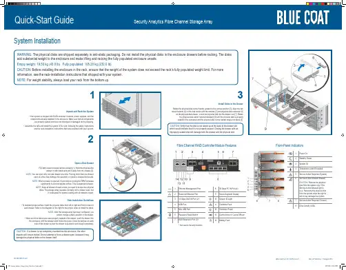
CAUTION: Remove the physical disk from the system only if the Service Action Allowed light is blue. Removing the physical disk from the system when the light is not lit may damage the system. 7 Service Action Required (Drawer)
Empty weight: 19.50 kg (43.0 lb) Fully populated: 105.20 kg (232.0 lb)
CAUTION: Before installing the enclosure in the rack, ensure that the weight of the system does not exceed the rack’s fully populated weight limit. For more information, see the rack-installation instructions that shipped with your system.
8 Drive Activity LEDs
Blue Coat Part: 231-03274 rev A.0
Date of Publication: 10 August 2018
8/10/2018 12:04:11 PM
Quick-Start Guide
System Installation (cont.)
Compact GuardLogix 5380 SIL 2 安装指南说明书
安裝說明Compact GuardLogix 5380 SIL 2 控制器Compact GuardLogix® 5380 控制器是具有整合式安全功能的可程式自動控制器。
Compact GuardLogix 5380 SIL 2 控制器可在達到並包含安全完整性等級 (SIL) 2 與效能等級 (d) 的功能安全應用中使用。
使用 Studio 5000 Logix Designer® 應用程式設定 Compact GuardLogix 5380 控制器。
關於如何在安裝之後使用控制器的更多資訊 (包括安全應用要求),請參閱其他資源(第14頁)中所列出版品。
變更摘要此出版物已修訂新增間隔與操作溫度資訊。
如需詳細資訊,請分別參閱(第5頁)與(第13頁)。
型號5069-L306ERS2、5069-L306ERMS2、5069-L310ERS2、5069-L310ERMS2、5069-L320ERS2、5069-L320ERS2K 、5069-L320ERMS2、5069-L320ERMS2K 、5069-L330ERS2、5069-L330ERS2K 、5069-L330ERMS2、5069-L330ERMS2K 、5069-L340ERS2、5069-L340ERMS2、5069-L350ERS2、5069-L350ERS2K 、5069-L350ERMS2、5069-L350ERMS2K 、5069-L380ERS2、5069-L380ERMS2、5069-L3100ERS2、5069-L3100ERMS2主題 頁次關於控制器5準備工作5將配接卡安裝到 DIN 導軌上7連接外接式電源供應器至控制器7安裝端蓋10開啟系統電源10設定網際網路通訊協定 (IP) 位址10將控制器連接至 EtherNet/IP 網路11移除或更換控制器12規格13歐洲機械規定核准14其他資源142Rockwell Automation 出版5069-IN014B-ZC-P - 2018年6 月Compact GuardLogix 5380 SIL 2 控制器ATTENTION:Read this document and the documents listed in the Additional Resources section about installation, configuration and operation of this equipment before you install, configure, operate or maintain this product. Users are required to familiarize themselves with installation and wiring instructions in addition to requirements of all applicable codes, laws, and standards.Activities including installation, adjustments, putting into service, use, assembly, disassembly, and maintenance are required to be carried out by suitably trained personnel in accordance with applicable code of practice.If this equipment is used in a manner not specified by the manufacturer, the protection provided by the equipment may be impaired.注意:在安装、配置、操作和维护本产品前,请阅读本文档以及“其他资源”部分列出的有关设备安装、配置和操作的相应文档。
TSC_Carat2024-A(AE)系列安装手册(v1[1][1].4)
I
TSCTM Carat2024-A/AE 系列工业以太网交换机 安装手册
目录
附录B 光纤相关知识 ........................................................................ 12
插图目录.............................................................................................. III
前 言 ................................................................................................. IV
图标说明
图标
说明 警告
危险标识,表示您处在一个可能引起身体损害的场 合中。在您任何操作之前,您必须意识到这种由电 气引起的危险并且尽量按照标准的操作方法去避免 这种危害发生。
注意 提示用户在操作过程中需要注意的地方。
提示 表示给用户提示的附加说明信息。
IV
TSCTM Carat2024-A/AE 系列工业以太网交换机 安装手册
1.1 端口性能 ............................................................................................................. 1 1.2 交换性能 ............................................................................................................. 1 1.3 管理性能 ............................................................................................................. 2
惠普企业安全产品ArcSight Activate安装指南说明书
HP E nterprise S ecurity P roductsHP Enterprise Security Products GlobalServicesArcSight Activate Wiki Install GuideFebruary 12, 2015ContentsDelivery D ocument P urpose a nd S cope (3)Installation P re-‐Requisites (4)Download W iki C ontent: (4)Download 64-‐Bit C entOS 6.6 “Minimal” I SO I mage: (4)Configure S erver o r V irtual M achine f or C entOS (4)Virual M achine I nstallation a nd C onfiguration (5)Mount I nstallation I SO (5)Boot V irtual M achine (5)Install a nd C onfigure C entOS O perating S ystem (5)Foswiki I nstallation (13)Download R PMs (13)Create F oswiki Y UM R epository (13)Install M akecache (13)Install F oswiki a nd P lugins (14)Disable I PTables F irewall (14)Navigate t o F oswiki W eb I nterface (15)Activate C ontent I nstallation (17)Upload A ctivate W iki C ontent t o V M (17)Extract A ctivate W iki C ontent (17)Grant O wnership t o A ctivate W iki C ontent (17)Navigate t o A ctivate C ontent (18)Support I nformation (20)Delivery Document Purpose and ScopeThe p urpose o f t his d ocument i s t o p rovide g uidance o n i nstalling t he A rcSight A ctivate W iki.The A ctivate W iki i s a s et o f d ownloadable c ontent t hat c an b e d eployed o n t he o pen-‐source “Foswiki” application.This c an b e p erformed o n a l ocal F oswiki i nstall, h osted o n a d edicated s erver w ith F oswiki, h osted within a v irtual m achine (VM), o r u sing a n a lternative m ethod s uch a s “Foswiki o n a U SB s tick”. These i nstructions d etail h ow t o i nstall t he A ctivate W iki c ontent o n F oswiki, w ithin a V M w ith C entOS 6.6 a s t he o perating s ystem.Installation Pre-‐RequisitesDownload Wiki Content:The A ctivate W iki c ontent i s a vailable t hrough t he H P P rotect 7/24 c ustomer f orum (account registration r equired):https:///groups/activate-‐frameworkSearch f or t he “Wiki C ontent” l ink, a nd d ownload t he “activate-‐wiki.tar.gz” f ile.Download 64-‐Bit CentOS 6.6 “Minimal” ISO Image:The A ctivate W iki i s s upported o n C entOS 6.6. T he I SO i mage c an b e d ownloaded t hrough t he following l ink:/centos/6/isos/x86_64/The I SO i mage f ile n ame i s “CentOS-‐6.6-‐x86_64-‐minimal.iso”Configure Server or Virtual Machine for CentOSThe s ystem r equirements f or C entOS m inimal a re 1 G B o f R AM a nd 5 G B o f d isk s pace.The i nstallation h as b een t ested s uccessfully o n a V irtual M achine w ith t he f ollowing c onfiguration: •1024 M B o f R AM•1 C PU C ore•5 G B o f D isk S pace•Internet A ccess (configure n etwork s ettings a ccording t o y our e nvironment)Create a V irtual M achine i n t he V M a pplication o f y our c hoice, w ith t he r ecommended s ystem configuration a bove.Virual Machine Installation and ConfigurationMount Installation ISOConfigure t he V M t o m ount t he C entOS i nstallation I SO t hat w as d ownloaded i n a p revious s tep.Boot Virtual MachineStart u p t he V M w ith t he i nstallation m edia l oaded.Install and Configure CentOS Operating SystemFollow t hrough t he i nstallation s teps b elow.Select “Install o r u pgrade a n e xisting s ystem”Select “Skip”Select “Next”Select y our l anguage o f c hoice, t hen c lick “Next”.Select y our k eyboard o f c hoice, t hen c lick “Next”.Select “Basic S torage D evices”, t hen c lick “Next”.Select “Yes, d iscard a ny d ata”.Configure y our V M’s h ostname a s d esired, t hen c lick “Configure N etwork”.Select “System e th0” t hen c lick “Edit”. C heck “Connect A utomatically” a nd c onfigure y our n etwork settings f or y our e nvironment. T he c onfiguration i s u nique t o y our e nvironment, b ut c onfigure t he settings s o t hat y our V irtual M achine w ill b e a ble t o c onnect t o t he i nternet f or t he p urpose o f downloading R PMs a nd c ontent.Select y our d esired T ime Z one, t hen c lick “Next”Enter a p assword f or t he r oot u ser a ccount, t hen c lick “Next”.Select “Use A ll S pace” t hen c lick “Next”.Click “Format”Click “Write c hanges t o d isk”Leave t he d efault s ettings a s-‐is, a nd c lick “Next”.The i nstallation w ill n ow c ommence.The i nstallation h as c ompleted. C lick “Reboot”.Foswiki InstallationOnce t he V M h as r ebooted, l og i n a s r oot v ia l ocal c onsole o r S SH a nd p erform t he f ollowing s teps.Download RPMsDownload t he E PEL R PMs w ith t he f ollowing c ommand:rpm -‐Uvh /pub/epel/6/x86_64/epel-‐release-‐6-‐8.noarch.rpmSample O utput:[root@activatewiki ~]# rpm -‐Uvh /pub/epel/6/x86_64/epel-‐release-‐6-‐8.noarch.rpm Retrieving /pub/epel/6/x86_64/epel-‐release-‐6-‐8.noarch.rpmwarning: /var/tmp/rpm-‐tmp.Y7H0d7: Header V3 RSA/SHA256 Signature, key ID 0608b895: NOKEYPreparing... ########################################### [100%]1:epel-‐release ########################################### [100%]Create Foswiki YUM RepositoryNavigate i nto t he /etc/yum.repos.d/ d irectory, a nd d ownload t he f oswiki r epositories l ist b y e xecuting the f ollowing c ommands:cd /etc/yum.repos.d/curl /Foswiki_rpms/foswiki.repo > foswiki.repoSample O utput:[root@activatewiki ~]# cd /etc/yum.repos.d/[root@activatewiki yum.repos.d]# curl /Foswiki_rpms/foswiki.repo > foswiki.repo% Total % Received % Xferd Average Speed Time Time Time CurrentDload Upload Total Spent Left Speed174 174 174 174 0 0 194 0 -‐-‐:-‐-‐:-‐-‐ -‐-‐:-‐-‐:-‐-‐ -‐-‐:-‐-‐:-‐-‐ 654Install MakecacheInstall “Makecache” w ith t he f ollowing c ommand:yum makecacheSample O utput:[root@activatewiki yum.repos.d]# yum makecacheLoaded plugins: fastestmirrorbase | 3.7 kB 00:00base/group_gz | 216 kB 00:01 base/filelists_db | 6.1 MB 00:54 base/primary_db | 4.6 MB 00:29 base/other_db | 2.8 MB 00:29 epel/metalink | 15 kB 00:00 epel | 4.4 kB 00:00 epel/group_gz | 237 kB 00:01 epel/filelists_db | 9.0 MB 01:08epel/primary_db | 6.3 MB 00:48 epel/other_db | 3.8 MB 00:37 epel/updateinfo | 943 kB 00:06 extras | 3.4 kB 00:00 extras/filelists_db | 31 kB 00:00 extras/prestodelta | 605 B 00:00 extras/primary_db | 30 kB 00:00 extras/other_db | 37 kB 00:00 foswiki | 2.7 kB 00:00 foswiki/filelists_db | 3.1 MB 00:25 foswiki/primary_db | 1.3 MB 00:08 foswiki/other_db | 334 kB 00:01 updates | 3.4 kB 00:00 updates/filelists_db | 1.5 MB 00:24 updates/prestodelta | 194 kB 00:12 updates/primary_db | 2.1 MB 00:14 updates/other_db | 19 MB 02:25 epel/pkgtags | 1.3 MB 00:10 Metadata Cache CreatedInstall Foswiki and PluginsInstall “Foswiki” a nd s everal p lugins w ith t he f ollowing c ommand. A nswer “Y” t o a ny p rompts.yum install foswiki foswiki-‐workflowplugin foswiki-‐jscalendarcontrib foswiki-‐ldapcontribSample O utput (trimmed f or l ength):[root@activatewiki yum.repos.d]# yum install foswiki foswiki-‐workflowplugin foswiki-‐jscalendarcontrib foswiki-‐ldapcontrib Loaded plugins: fastestmirrorSetting up Install ProcessLoading mirror speeds from cached hostfile* base: * epel: * extras: * updates: Resolving Dependencies-‐-‐> Running transaction check-‐-‐-‐> Package foswiki.noarch 0:1.1.9-‐291 will be installed-‐-‐> Processing Dependency: foswiki-‐wysiwygplugin for package: foswiki-‐1.1.9-‐291.noarch-‐-‐> Processing Dependency: foswiki-‐twistyplugin for package: foswiki-‐1.1.9-‐291.noarch-‐-‐> Processing Dependency: foswiki-‐twikicompatibilityplugin for package: foswiki-‐1.1.9-‐291.noarch-‐-‐> Processing Dependency: foswiki-‐topicusermappingcontrib for package: foswiki-‐1.1.9-‐291.noarch-‐-‐> Processing Dependency: foswiki-‐tipscontrib for package: foswiki-‐1.1.9-‐291.noarch-‐-‐> Processing Dependency: foswiki-‐tinymceplugin for package: foswiki-‐1.1.9-‐291.noarch-‐-‐> Processing Dependency: foswiki-‐tableplugin for package: foswiki-‐1.1.9-‐291.noarch...<REMOVED MANY LINES>...Complete!Disable IPTables FirewallDisable I PTables (or c onfigure i t) s o t hat y ou c an c onnect t o t he V M f rom y our l ocal m achine’s w eb browser, o ver p ort 80 a nd 443. T he e asiest m ethod i s t o j ust d isable i t u sing t he f ollowing c ommands:/etc/init.d/iptables stopchkconfig iptables offSample O utput:[root@activatewiki yum.repos.d]# /etc/init.d/iptables stopiptables: Setting chains to policy ACCEPT: filter [ OK ]iptables: Flushing firewall rules: [ OK ]iptables: Unloading modules: [ OK ][root@activatewiki yum.repos.d]# chkconfig iptables offNavigate to Foswiki Web InterfaceNow t hat F oswiki i s i nstalled, o pen a w eb b rowser o n y our l ocal m achine a nd c onnect t o: http://<IP_Address_of_VM>/foswiki/bin/configureOnce c onnected, y ou s hould s ee t he f ollowing F oswiki c onfiguration i nterface:You m ay w ish t o p erform i nitial c onfiguration t asks, b ut w e’ll a ssume t hat y our n etwork i s c onfigured so t hat o nly y our l ocal m achine c an a ccess t he V M, a nd t hat y ou d o n ot n eed t o l ock d own a ny security c onfiguration.Activate Content InstallationWith F oswiki u p a nd r unning o n y our V M, t he o nly s tep r emaining i s t o c opy t he A ctivate W iki c ontent onto y our V M, a nd i nstall i t i nto p lace.Upload Activate Wiki Content to VMTransfer t he A ctivate W iki c ontent t hat y ou d ownloaded e arlier (activate-‐wiki.tar.gz) o nto y our V M i n “/var/lib/foswiki/”. A r ecommended m ethod w ould b e S CP’ing t he f ile o nto t he V M.Extract Activate Wiki ContentNavigate t o /var/lib/foswiki/:cd /var/lib/foswiki/Untar t he W iki C ontent:tar –zxvf activate-‐wiki.tar.gzSample O utput (trimmed f or l ength):[root@activatewiki foswiki]# tar -‐zxvf activate-‐wiki.tar.gzdata/ArcSightActivate/data/ArcSightActivate/WebSenseProxyConfigurationGuide.txt,vdata/ArcSightActivate/BestPracticesRules.txt,vdata/ArcSightActivate/WebChanges.txt,vdata/ArcSightActivate/MicrosoftWindowsL1ConfigurationGuide.txtdata/ArcSightActivate/CiscoSecureAcsConfurationGuide.txt,vdata/ArcSightActivate/ActivateOperatingSystemMonitoring.txtdata/ArcSightActivate/CheckPointActivateInstallConfig.txt,vdata/ArcSightActivate/WebNotify.lock...<TRIMMED LINES FOR LENGTH>...pub/System/ProjectLogos/HP_Blue_RGB_72_LG.gifpub/System/ProjectLogos/HP_Blue_RGB_72_MD.gifpub/System/ProjectLogos/HP_Blue_RGB_72_MN.gifpub/System/ProjectLogos/HP_Blue_RGB_72_MX.gifpub/System/ProjectLogos/HP_Blue_RGB_72_SM.gifGrant Ownership to Activate Wiki ContentChange t he o wnership o f t he “data” a nd “pub” d irectories t o t he “apache” u ser a ccount a nd g roup, b y using t he f ollowing c ommands:chown -‐R apache:apache /var/lib/foswiki/data/chown -‐R apache:apache /var/lib/foswiki/pub/Navigate to Activate ContentNow t hat t he A ctivate W iki C ontent i s i n p lace, u se a w eb b rowser o n y our l ocal m achine t o n avigateto t he f ollowing a ddress:http://<IP_Address_of_VM>/foswiki/Click t he “ArcSightActivate” w ebs l ink i n t he l ower-‐left c orner:The A rcSight A ctivate W iki i s n ow i nstalled a nd a vailable f or u se:Support InformationPlease n ote t hat t his p rocess i s N OT o fficially s upported b y H P.All A ctivate-‐related i nformation c an b e a ccessed a t t he f ollowing l ocation:https:///groups/activate-‐frameworkIf a ny s upported i ssues a rise, o r i f y ou h ave a ny q uestions, p lease v isit o ur S oftware S upport O nline website.HP S oftware S upport O nline (/go/hpsoftwaresupport) i s a vailable t o y ou around t he c lock, 24x7, e nabling y ou t o:•Search t he t echnical k nowledge b ase f or k nown p roblems, t echnical d ocuments, m anuals a nd patches•Log, t rack a nd u pdate s upport i ncidents e lectronically t hrough a s ecured e nvironment•Review, r evise, a nd r enew a n H P S oftware S upport C ontract•Register t o r eceive e-‐mail n otifications a nd a ccess t o e lectronic d ownload o f m any H P s oftware products•Download t he l atest s oftware p atches f or H P s oftware p roducts。
紫光恒越FIST安装指导手册说明书
UNIS服务器FIST安装指导紫光恒越技术有限公司资料版本:6W100-20210831Copyright © 2021 紫光恒越技术有限公司及其许可者版权所有,保留一切权利。
未经本公司书面许可,任何单位和个人不得擅自摘抄、复制本书内容的部分或全部,并不得以任何形式传播。
UNIS为紫光恒越技术有限公司的商标。
对于本手册中出现的其它公司的商标、产品标识及商品名称,由各自权利人拥有。
由于产品版本升级或其他原因,本手册内容有可能变更。
紫光恒越保留在没有任何通知或者提示的情况下对本手册的内容进行修改的权利。
本手册仅作为使用指导,紫光恒越尽全力在本手册中提供准确的信息,但是紫光恒越并不确保手册内容完全没有错误,本手册中的所有陈述、信息和建议也不构成任何明示或暗示的担保。
前言本手册介绍了FIST的安装准备工作、FIST的安装、登录、使用与卸载方法等内容。
前言部分包含如下内容:•读者对象•本书约定•资料意见反馈读者对象本手册主要适用于如下工程师:•网络规划人员•现场技术支持与维护人员•负责服务器配置和维护的管理员本书约定1. 命令行格式约定格式意义粗体命令行关键字(命令中保持不变、必须照输的部分)采用加粗字体表示。
斜体命令行参数(命令中必须由实际值进行替代的部分)采用斜体表示。
[ ] 表示用“[ ]”括起来的部分在命令配置时是可选的。
{ x | y | ... }表示从多个选项中仅选取一个。
[ x | y | ... ]表示从多个选项中选取一个或者不选。
{ x | y | ... } *表示从多个选项中至少选取一个。
[ x | y | ... ] *表示从多个选项中选取一个、多个或者不选。
&<1-n>表示符号&前面的参数可以重复输入1~n次。
# 由“#”号开始的行表示为注释行。
2. 图形界面格式约定格式意义< > 带尖括号“< >”表示按钮名,如“单击<确定>按钮”。