
CT400分布光度计控制器用户手册v1.02.doc
Ver1.02杭州远方光电信息有限公司EVERFINEPHOTO-E-INFOCO.,LTD.地址:杭州市滨江区滨康路669号1号楼(310053)ADD:Bldg.1,#669BinkangRd.,BinjiangHi-TechZone,Hangzhou,China(310053)Tel:86-571-86698333Fax:86-571-86696433E-mail:Sales@everfine.cn销售专箱Service@everfine.cn服务专箱http://www.everfine.cn
CT400分布光度计转台控制器用户手册
CT400GONIOPHOTOMETERSCONTROLLERUSER’SMANUAL--1
前言感谢您使用远方:分布光度计转台控制器本说明书讲述该设备的功能及操作。为了确保正确使用仪器,在操作仪器前请仔细阅读本用户手册。请妥善保存本手册,以便遇到问题时快速查阅。
注意:本手册内容有可能变动,恕不另外通知,但可保证本手册书与所购仪器一致。我们已经尽最大努力准备本手册,以确保其准确性。如您有疑问或发现错误,请直接与本公司或本公司授权代理商联系。没有本公司书面许可,任何抄袭或改编本手册全部或部分内容均为严重侵权。用户第一次打开仪器包装箱时,请对照装箱清单,检查仪器和配件,若发现配件不齐或仪器配件不正常,请立即与销售商联系。--2
特别警告1.在使用本设备前请认真阅读本用户手册。2.请按用户手册要求正确接线,否则可能不能正常工作。3.仪器电源使用单相220V,50Hz/60Hz,且必须可靠接地。--3目录目录............................................................................................3第一章概述.........................................................................................4第二章主要功能及主要技术指标.....................................................5一、原理框图及主要功能...............................................................5二、转台控制器的主要技术指标:...............................................5第三章操作.......................................................................................7一、CT400分布光度计转台控制器的相关操作...............................7二、GRC-1遥控器的使用说明.........................................................15第四章注意事项...............................................................................17--4
第一章概述CT400分布光度计转台控制器是本公司分布光度计专用的显示、控制仪器。控制器采用CAN总线方式与分布光度计测试系统连接,并进行高速数据交换。可以实时显示转台角度值和被选中的照度测试通道的测量值,同时可以通过面板上的按键控制转台转动,以及照度测试通道的选择和设置。控制器配有GRC-1遥控器,可通过遥控器控制转台转动和停止。--5
第二章主要功能及主要技术指标一、原理框图及主要功能
CAN总线接口
GRC-1遥控器
微处理器
显示按键
图1原理框图1.主要功能1)可提供分布光度计转台控制信号。
2)可显示自动转台两个转轴的角度值;同时可以显示一个主通道光度测量值和一个辅助通道测量值。3)可控制自动转台的相对角位移,即在当前的位置基础上实现精确的角度定位。4)具备CAN总线接口,可与测试系统实现高速通讯,实时显示各测量值。5)可配置GRC-1遥控器进行遥控。
二、转台控制器的主要技术指标:1.角度显示形式:度或度.分.秒。
2.最大显示范围:-360.000度~+360.000度(或-360度00分00秒~+360度00分00秒)。--6
3.光度主通道可显示照度值或光强值;辅助通道显示相对测量值。4.具有系统报警声光指示功能。5.具备按键操作功能,可通过按键设置和查看系统参数。
6.外形尺寸(W×H×D):425mm×177mm×263mm7.重量:约5kg8.允许工作条件:温度:10℃~35℃;湿度:≤80R.H.电源:AC198V~242V,50Hz~60Hz--7
第三章操作CT400控制器是一个显示、控制仪器。可以实时显示当前转台转轴的角度值和光度测试通道的测量值;可以通过按键设置控制转台作相对角位移(即在当前的位置上转过一个设定的角度)和转台转动速度;还可以通过按键设置进行光度测试通道的定标、校零、参数查看等操作。一、CT400分布光度计转台控制器的相关操作1.面板和操作指示灯
(1)CT400的前后面板如图2、图3所示
图2CT400前面板1角度显示窗口:显示两个转轴的角度测量值。2单位指示灯:指示当前显示值是以度为单位或以度分秒为单位。3报警指示灯:当系统出现故障发生报警时该指示灯被点亮4转台部分控制按键:“设置/SETUP”:用于控制转台作相对转动、设置速度和显示单位等。“复位/RESET”:用于控制转台回到零位。“∧”、“>”:在设置和复位操作时,用于改变光标所在位置的数值和光--8
标的位置。“确认/ENTER”:确认设置参数。“停止/STOP”:停止当前转动操作。⑤电源开关:控制器供电开关。⑥光度测试部分显示窗口:显示主通道和辅助通道光度测试值。⑦光度测试值单位指示灯。⑧光度测试部分按键:“设置/SETUP”:用于设置显示参数、查看并设置量程、光度定标等操作。“校零/ZERO”:用校零操作。“锁存/HOLD”:用于所存当前被选择通道的显示值。“·”、“∧”、“>”:用于小数点移动和改变光标所在位置的数字以及光标位置。
图3CT400后面板1遥控器连接端口:用遥控器所配的电缆和遥控器相连。2转台接口:转台连接的端口。3接地端子:控制器接大地端子。--9
4保险丝:内装快速熔断保险丝。5电源插座:控制器电源输入。(2)操作指示CT400分为两个操作区块,一个区块是转台部分相关操作;另一个是光度测试部分相关操作。转台部分相关操作区块有两个显示窗口,每个窗口有7个数码管用于显示转台两个转轴的角度测量值。角度单位可选择为“度”或“度.分.秒”,具体操作请参见“3.操作键”一节内容。(a)当转轴转动时,显示窗口会显示当前转动轴的角度并随之刷新。(b)当控制转轴进行复位时,窗口会根据当前正在进行复位操作的转动轴显示“RESET”。(c)当测试系统发生出错报警时,面板上的“报警/ALARM”指示灯会被点亮,显示窗口也会显示相关信息。(d)当控制器和系统总线脱离或转台和探测器电源未接通时,窗口会显示“NO-LINK”。光度测试部分相关操作区块有两显示窗口,每个显示窗口有7个数码管用于显示光度主通道和辅助通道的测试值。主通道光度测试值可通过按键设置显示照度值或光强值,具体操作请参见“3.操作键”一节内容。(a)主通道显示窗口显示当前被选中主探测器(若系统中主光度探测器多于一个)的光度测量值。探测器序号在窗口的左边第1位显示。按“∧”键可切换显示主通道探测器。若在测试状态下,只能显示当前测试使用的主通道探测器。(b)辅助通道显示窗口显示当前辅助探测器测试值。--10
2.硬件的连接(1)CT400仪器通讯接口为CAN总线接口,后面板上转台接口(9芯阴插)第4为CANH,第5脚为CANL,第9脚为GND。仪器通过CAN通讯线与系统总线相连实现数据交换。测试系统在出厂时都配有CAN通讯电缆,用户只需把电缆上的相应插头插到后面板上的“转台接口”端口即可。(2)当转台在进行复位操作时,(3)用户若要使用GRC_1遥控器,只需将遥控器上所配的通讯电缆一端连接至CT400后面板上的遥控端口[图3中的①],另一端接至GRC-1遥控器接口处。若无需使用GRC_1遥控器,此端口可不接。3.操作键如上所述,CT400作为自动转台的显示、控制设备,能对自动转台作相对角位移的控制,即在当前位置的基础上作精确的角度转动。此外,还可以通过按键操作来控制自动转台完成复位操作。这些控制都是通过控制器前面板上的按键来实现的。3.1转台控制部分:(1)相对角位移设定键:设置/SETUP、∧、>、确认/ENTER“设置/SETUP”:在空闲状态下按下“设置/SETUP”键,进入设定状态;在设定状态下按下此键则退出设定状态。“∧”:光标所在处是数字,则数字循环加一(9加1为0);若光标所在处不是数字,则是设定转轴或转动方向。“>”:光标循环右移。按下“设置/SETUP”键,选择“ANGLE”菜单,按“确认/ENTER”键进入角度设定界面,通过按“∧”与“>”键来选择转动轴(A轴或C轴)与相对角位移的设定,在设定过程中可以在第2窗口查看到以设定角
ETC-400说明书

红慢闪 参数设置
按键功能
◆ 正常库温显示状态下:
◇ 键:按下即松开,闪烁显示设置的温度上限值2秒后显示正常温度。 ◇ 键:按下即松开,闪烁显示设置的温度下限值2秒后显示正常温度。 ◇ SET键: (非化霜状态)按下即松开,闪烁显示化霜周期、化霜时间,2秒后显示正常温度;
参数项代码,按 或 键调整参数项F01,F02…
◇ 进入参数项设置状态后,按 键显示上一次设定的参数值,按 或 键改变参数值,再
按SET键,更改的参数被暂时储存, 同时回到原参数项, 再按 或 键显示下一个参数项 时, 按 键又显示上一次设定值,按 或 键改变参数值, 按SET键暂时保存改变值并回 到原参数项,依此类推,可以更改所有参数项的参数值。
◇
键:按下即松开,闪烁显示化霜探头温度、剩余化霜周期,2秒后显示正常温度。 按住持续3秒以上,可启动或退出手动化霜。
操作说明
◆ 锁/开键盘锁: 机器上电后,同时按 + 3秒以上,LED显示"POF"表示锁定键盘,均显示"POF"2秒后显 示正常温度, 在键盘锁定状态下同时按 + 3秒以上, LED显示"PON" ,表示键盘开锁, 2秒后显示正常温度,此时可以进入按键功能,进行查看或重新设定各种参数。 ◆ 参数调整:
◇ 当所有参数调整完成后, 再按SET键3秒以上予以确认并退出参数设置状态返回温度测量状
态,如所有参数调整完成后不按SET键3S确认退出, 30秒内也无按键操作, 系统会自动退出 参数设置状态,返回测温状态,但系统不保存已改变的参数值,按原设定值运行。
参数为20时取消超温限报警
ETC
共 点 点 闭
常 压 缩 机
化 霜 机
风 报 警
库温传感器
化霜传感器 电源 220VAC
400W 黑光灯160.028用户手册说明书
400W BLACK LIGHT160.028USER MANUALINTRODUCTIONCongratulations on the purchase of your new our company lighting effect. We are confident you will enjoy many trouble free hours with this unit . To assist with the care and use of the product we have prepared this short guide.OPERATIONBefore connecting this unit to the mains power supply for the first time you must first install the lamp .(See ‘Replacing Lamp’ for details).This lighting effect has been designed to function on a mains power supply of either 240V~50Hz and has been fitted with a suitable power plug for use with your local voltage. Check the label on the unit and the power plug for the correct voltage.When connected to the mains power supply the unit should illuminate. The 160.028 utilizes a mercury vapor lamp ,it will take 5 to 10 minutes to reach full intensity . The intensity of the lamp will increase with use. The light emitted by the 160.028 is invisible and does not have the glow of a fluorescent fixture.Due to the high operating temperature of halogen lamps it is advisable that the effect be used in well ventilated areas taking care not to obstruct the air vents. To maximize lamp life, allow the unit to cool down before moving or touching the lamp.CAUTIONDue to the nature of the mercury vapor lamp, this lamp must be allowed to cool down (about 5 to10 minutes) after being turned off before re-igniting. Failure to wait for cool down many cause the lamp to fail prematurely.INSTALLATION/MOUNTIONAlthough this unit can be used in an upright position , it is recommended that , for safety purposes ,your lighting effect be properly mounted using a suitable hanging clamp and safety cable . Our company offers a range of items , which are ideal for safe mounting .Use in a well-ventilated area without obstruction to air vents.REPLACING LAMPS1. Disconnect from main power supply before attempting to replace either lamp .2. Ensure that the unit is sufficiently cool , before removing blown lamps.3. Never touch new lamps with your fingers: use a tissue or a cloth.In order to replace the lamp, disconnect from main power supply first, and unscrew the lamp replacement cover. Only use the appropriately rated lamps as use of any other lamp type many cause the unit to be non-operational.Due to the nature of halogen lamp it is vitally important that you do not touch the new replacement lamp with your fingers, as this will reduce lamp life considerably. Once again a tissue or cloth can be used for fitting the replacement lamp.If after replacement of the lamp, the unit is still not working then please contact your dealer or our company for servicing.CLEANINGThe most important part of your lighting effect to keep clean is the reflector as it allows the light output to transmit. This should be cleaned with a soft damp cloth. The body of the unit may also be cleaned in the same way . We recommend internal cleaning be carried out by a fully qualified technician.MAINTENANCE & SERVICINGWork on internal parts should be carried out by a qualified technician. Removal of covers other than the front to replace lamp is considered a breach of warranty and will not be covered under any such agreement unless authorized first by the company.TROUBLESHOOTING• If the unit is not functional-check main power supply is ‘on’.• If the unit is functional but lamp does not light-lamp may require replacing.• If after trying this solution you still have a problem contact your dealer or our company for service. CAUTIONDo not obstruct the air vents.Do not touch unit or lamps while hot.Never put any objects through the air grill on the top of the unit.No user serviceable parts inside, please refer to our company.POWER CONNECTIONSThe unit is supplied with a power plug appropriate to its voltage and destination. Should any other connections be required they must be carried out with the following configuration.Earth = Green/Yellow cableNeutral = Blue cableLive = Brown cableIn the USA & Europe, it is required that all plugs are 3-pin type i.e. with Earth/Ground connection. In the UK, it is required that all mains plugs are fitted with 5A fuses.TECHNICAL SPECIFICATIONSAC Power 240V~50Hz Lamps E40 400W Mercury VaporPart No H400BLFuse 250V/5A imensionsD 375x388x413mm Weight 13.5kg。
LST400-中文操作手册

pasl npasnpawnawintwhitwhitehitmehtmeptmepemrpearpetauretaruretaruetruere notainotinon tgdortgoartgpargphariphaciphcdihcdiiscdipsdiplsaiplsyaplyalyay
•oLadoLadoaindaigndign&ign&g&& BBaBgaBgagaingigngignHignHogHopHopopeprespresresrs
ro42r042042V04AV0AVCAVC;AC±; C±;1- ±;51安±%51%5装1%55说%05明/056/0506–/006第/H06Hz08H,z页H,z,z, •sIssIsosIolsaIolstaeoltadeltadet4de4-d4-24-20-20m20mA0mAmOAOuAOtupOtuputuptutpwtuwtuitwthitwhiHthiHtAhHARHARTART7RT7T77
×637×7ihcniehcnsehcseh/se/1s/91/291×291×29×23×032×032×039×049×49494 •s5s5sC5Co5ConCofnigofnigufnigrufaigrubarubalerbaleRbleReleRleaRleyalesyalsya/sy/8s/8A/8Am8AmpAmpmpp
操作说明书OI/LST400-ZH Rev.A
LST400 超声波物位计
evevevevel el /l /l /O长/OO量pOppe程peen超ennnC声CCh波Chha物haanan位nnne/ne流el el Fl量Fl FloF计lololwowwwTTTrTrararanannsnsmsmsmmitititietetererrr
PS400系列保护测控装置说明书V1.42(Modbus)

V2.16 V2.15 V2.10 V2.09 V2.09 V2.08 软件版本号
2012-12-30 2012-07-24 2010-8-5 2010-1-7 2009-9-29 2009-7-13 修改日期
* 技术支持
电话:(025)51858272 传真:(025)51858972
* 本说明书可能会被修改,请注意核对实际产品与说明书的版本是否相符 * 2009 年 7 月 第 1 版 第 .............................................................................................................................................................. 5 1 概述 ............................................................................................................................................................................. 5 1.1 主要用途及方案 .................................................................................................................................................. 5 1.2 技术特点 ...............................................................................
CR-400色差仪说明书
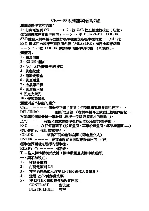
CR—400系列基本操作步驟測量頭操作基本步驟:1、打開電源到ON -->2、按CAL校正鍵進行校正(注意:每次開機都需要進行校正)-->3、按T (TARGET COLORSET)鍵進入標準樣界面進行標準樣選定或標準樣測量-->4、按ESC 鍵返回比較樣界面按測色鍵(MEASURE)進行比較樣測量-->5、按COLOR鍵選擇所需的色彩空間(可選擇)。
測量頭:1、電源開關2、RS-232連接口3、AC—A17(變壓器)連接口4、測色按鍵5、電池安裝盒6、測量頭蓋7、液晶顯示屏8、測量指示燈9 固定支架孔10、安裝掛帶孔測量頭基本按鍵的簡介:CAL ----儀器校正鍵(注意:每次開機都需要進行校正)。
DEL/UNDO ----刪除/取消鍵(在標準樣界面或在比較樣界面按一次該鍵即刪除最後一筆數據,再按一次則取消剛才的刪除)。
△/▽----移動光標或在標準樣界面查找所需的標準樣。
ESC----在任何畫面下(校正畫面、菜單設置畫面、標準樣畫面…..)按此鍵則返回到比較樣畫面。
COLOR----切換不同的色彩空間(即色差公式)ENTER ----在菜單設置界面改變設置內容、在標準樣界面確定選擇的標準樣。
READY ○----指示燈。
T -進入標準樣模式按鍵(標準樣測量或標準樣選擇)。
一、顯示和設定:1、連接好電源2、打開電源到ON3、在開始屏幕顯示時按ENTER鍵進入菜單界面4、通過△/▽鍵移動光標5、按ENTER鍵改變選項設定內容CONTRAST 對比度BLACK LIGHT 背光BAUDRATE 比特率PC MODE 連電腦模式6、設定完成後按ESC退出二、儀器校正1、在開機或測量屏幕下按CAL鍵進入儀器校正界面,第一次開機或初試化後儀器校正時都需要輸入白板數值,使用△/▽、ENTER鍵輸入白板數值。
2、把測量頭放在白板上按測色鍵進行校正。
三、標準樣測量1、按T鍵進入標準樣測量界面2、測量新標準樣再按T鍵(或按△/▽進行標準樣選定)3、把測量頭放在標準樣上按測色鍵進行測量數據處理機:1、電源開關 2 、RS-232連接口3、AC—A17(變壓器)連接口4、印表紙安裝盒5、印表機頭6、液晶顯示屏7、顯示屏對比度調節鍵8、電池安裝盒9、安裝掛帶孔10、蜂鳴器數據處理機基本按鍵簡介:1、CALIBRATION------校正鍵2、DELETE/UNDO-----刪除/取消鍵3、PRINT/FEED------列印/上紙鍵4、OPTION------功能鍵(設定允收誤差△E、平均測量次數、日期/時間、多通道校正)5、DISPLAY----不同模式顯示按鍵(差值/絕對值模式、坐標模式、合格/不合格、絕對值模式、差值模式)。
LT400手册

产品概述1编辑软件DP2002LT400操作方法3与PLC 的连接方法4LT400可编程文本显示器用户手册目录第一章产品概述1-1功能 ---------------------------------------------------------- 2 1-2一般规格 ------------------------------------------------------ 2 1-3各部分名称 ---------------------------------------------------- 2 1-4外形尺寸及安装方法 -------------------------------------------- 5第二章编辑软件DP2002-1 DP200概述 ---------------------------------------------------- 6 2-2-1 关于工程和画面 ------------------------------------------- 6 2-2-2 画面内容 ------------------------------------------------- 6 2-2-3 DP200 使用程式 ------------------------------------------- 6 2-2 编辑用户画面 -------------------------------------------------- 6 2-2-1 创建工程 ------------------------------------------------- 6 2-2-2 制作基本画面 --------------------------------------------- 8 2-2-3 DP200系统参数------------------------------------------- 9 2-2-4 文本 ----------------------------------------------------- 10 2-2-5 功能键(画面跳转)---------------------------------------- 12 2-2-6数据显示窗----------------------------------------------- 15 2-2-7数据设定窗----------------------------------------------- 18 2-2-8 指示灯--------------------------------------------------- 20 2-2-9功能键(开关量控制)------------------------------------- 23 2-2-10 棒形图-------------------------------------------------- 24 2-2-11 折线图 -------------------------------------------------- 25 2-2-12 报警列表 ------------------------------------------------ 26 2-3 保存工程 ------------------------------------------------------ 29 2-4 下载画面 ------------------------------------------------------ 29第三章LT400操作方法3-1 联机通讯 ----------------------------------------------------- 30 3-2 切换画面 ----------------------------------------------------- 30 3-3 系统口令 ----------------------------------------------------- 30 3-4 修改数据 ----------------------------------------------------- 32 3-5 开关量控制 --------------------------------------------------- 33第四章 PLC连接方法4-1 三菱FX系列 --------------------------------------------------- 34 4-2 西门子S7-200系列 --------------------------------------------- 35 4-2 欧姆龙C系列 -------------------------------------------------- 36 4-3 光洋SG系列 --------------------------------------------------- 37 4-4 施耐德NEZA系列 ----------------------------------------------- 38 4-5 台达DVP系列 -------------------------------------------------- 39 4-6 松下FP系列 --------------------------------------------------- 40 4-7 LG Master-K系列 ----------------------------------------------- 41第一章产品概述1-1功能LT400是可编程序控制器的小型人机界面,以文字或指示灯等形式监视、修改PLC内部寄存器或继电器的数值及状态.从而使操作人员能够自如地控制机器设备.LT400显示器有以下特长:通过编辑软件DP200在计算机上作画,自由输入汉字及设定PLC地址,使用串口通讯下载画面通讯协议和画面数据一同下载到显示器,无须PLC编写通讯程序对应PLC机种广泛,包括三菱FX系列、欧姆龙C系列、西门子S7-200系列、光洋SG系列等具有密码保护功能具有报警列表功能,逐行实时显示当前报警信息7个按键可被定义成功能键,可替代部分控制柜上机械按键自由选择通讯方式,RS232/RS422/RS485任选带背景光STN液晶显示,可显示24字符×4行,即12汉字×4行显示器表面IP65构造,防水、防油1-2一般规格2.环境条件操作温度 0~50℃保存温度 –10~60℃环境温度 20~85%(无凝露)耐振动 10~25Hz(X,Y,Z方向各30分钟2G)抗干扰电压噪声: 1000Vp-p周围空气无腐蚀性气体保护结构适合IP65F1-3 各部分名称LT400的正面除液晶显示窗之外,还有7个机械按键,触摸手感好、使用寿命长、安全可靠.7个按键除了具备基本功能外,还能被设定成特殊功能按键,直接完成画面跳转,开关量设定等功能。
四轴控制器使用说明书
四轴控制器使用说明书目录版权申明 .................................................................................................... 错误!未定义书签。
第一章概述 .. (5)1.1 产品简介 (4)1.2应用领域 (4)1.3图片展示 (4)第二章PCB结构及功能 (6)2.1 MCU简述 (5)2.2 PCD4641简述 (6)2.2.1PCD4641概要 (6)2.2.2特长 (6)2.2.3主要功能介绍 (6)2.3 MCU控制芯片方式说明 (8)2.4 调试接口接线线序说明 (10)2.5 BOOT接头说明 (11)2.6启动开关 (11)2.7电气接口 (12)2.7.1驱动器接头 (12)2.7.2运动反馈信号接头 (14)2.7.3励磁时序信号和通用IO口接头 (13)第三章FSMC简介及接线说明 (15)3.1 FSMC简述 (15)3.1.1 FSMC概要 (15)3.1.2 FSMC映射地址空间 (17)3.1.3 技术优势 (16)3.2 MCU访问PCD4641线序说明 (17)第四章MCU使用FSMC访问PCD4641的具体实现 (18)4.1 PCD4641A并行接口方法 (20)4.2 命令 (19)4.2.1 启动方式命令 (19)4.2.2 控制方式命令 (20)4.2.3 寄存器选择命令 (23)4.2.4 输出模式命令 (24)4.2.5状态寄存器 (26)4.3 具体的C语言实现 (24)第五章上位机通信 (28)5.1 上位机与四轴控制器的硬件连接 (28)5.2 上位机与四轴控制器的通信连接 (29)5.3 如何控制四轴控制器 (30)第六章四轴控制器开发环境使用说明 (36)6.1 与PCB板的硬件连接 (36)6.2 驱动的安装 (32)6.3 IAR开发环境的安装 (34)6.4 IDE相关设置 (35)6.5 程序的开发设计 (42)第七章下载程序 (43)7.1 用USB串口线连接四轴控制器 (39)7.2 下载程序 (44)第八章使用安全注意事项 (43)第一章概述1.1 产品简介感谢您选择脉冲电子四轴控制器,为回报客户,我们将以品质一流的四轴控制器、完善的售后服务、高效的技术支持,帮助您建立自己的运动控制系统。
超微量分光光度计 操作说明书
0.04 - 300A
OD600
吸光度范围:0~6.000 Abs 吸光度稳定性:[0,3)≤0.5%, [3,4)≤2% 吸光度重复性: 0,3)≤0.5%, [3,4)≤2%
操作系统
安卓操作系统
重量
5KG
操作界面
7寸触摸屏 1024×600高清显示
样品体积
0.5-2μL
核酸检测范围
2-15000ng/μl(dsDNA)
2. 遵循标准 • GB191-2008《包装、储运图示标志》 • GB4793.1-2007《医用电气设备 第一部分 安全通用要求》 • GB9706.1-2007《实验室仪器设备要求》 • GB/T13384-2008《机电产品包装通用技术条件》
3. 注意和警示信息 本手册介绍了L-SP-HB 超微量分光光度计的基本操作说明,包括如何启动、操作和维护该
核酸检测每次测量所需要的样品量仅需0.5至2ul即可。直接将样品点于加样板上。无需比 色杯或毛细管等附件。测量结束后,可以选择直接将样品擦去或者再用移液器回收样品。所有 步骤简单快速,一气呵成。可应用在临床疾病诊断、输血安全、法医学鉴定、环境微生物检 测、食品安全检测、分子生物学研究等多种领域。
3
第 二 章 特性
本手册所介绍的产品在出厂前均经过严格的检验,以确保产品的质量。为了保证其安全、 可靠的运行,获得最佳的实验效果,用户必须严格按照本手册所述的使用方法进行操作。另 外, 恰当的运输、仓储和安装及合理的操作和维护都有助于系统的安全正常运行。本手册介绍 了日常使用L-SP-HB 超微量分光光度计的信息,对L-SP-HB 超微量分光光度计的组成、安装、 操作和维护等内容作了详细的说明,同时也介绍了L-SP-HB 超微量分光光度计的性能特点。它 为操作人员提供了准确的使用参考。操作人员必须正确地理解本手册所提到的安全信息和警告 信息,并运用到实际操作当中去。
VGC401 中文手册
单通道控制器VGC 401使用说明书产品标识与INFICON联系时,请告知产品名牌上的信息。
为便于参考,现将名牌上的信息表示如下:有效性本说明书用于件号为398-010的产品。
件号(PN)可从产品名牌上看到。
本说明书件基于固件版号302-519-A。
如你的仪器工作与本文件的说明不符,请检查是否与上述固件版号(48)相符。
我们保留本说明书不事先通知的技术修改权。
全部尺寸均用毫米表示。
用途V GC401与INFICON生产的规管同时使用,用于真空系统的总压强测量。
全部产品必须按产品说明书使用。
供货范围1件单通道控制器1根电源电缆1根橡皮条2个橡皮脚4个凹槽螺丝4个塑料套管产品标识有效性用途供货范围1 安全1.1 使用符号1.2 人员要求1.3 一般安全规则1.4 责任与保修2 技术参数3 安装3.1 人员3.2 安装,设置3.2.1 机架安装3.2.2 安装在控制屏内3.2.3 用作桌上式仪器3.3 电源连接3.4 传感器连接3.5 控制器连接3.6 RS232接口连接4 运行4.1 面板4.2 VGC401的On和Off 4.3 工作模式4.4 测量模式4.5 参数模式4.5.1 参数4.6 测试模式4.6.1 参数4.6.2 测试程序5 维护6 故障查找7 检修8 附件9 储存10 废物处理附录A. 转换表提供的压强传感器B. 缺省参数C. 软件升级D. 文献E. 索引质量保证书参考在本说明书内的内容使用符号(XY)。
参考“文献”中的内容使用符号([Z])。
1.1 使用符号其它符号灯亮灯闪灯黑按此键(例:’para’键)不要按任何键.1.2 人员要求1.3 一般安全规则对于全部要进行的工作,必须遵守规章制度和采取必要的预防措施和考虑本说明书中的安全规则。
向所有其他用户通报安全信息。
1.4 责任与保修如最终用户或第三方发生以下情况,INFICON将不承担赔偿责任和保修将不再有效。
●不顾本说明书中的信息。
ARCO 400 一体化测试设备用于重闭器控制器说明书
ARCO 400Universal test set for recloser controlsSmart and rugged testing solution forCoping with modern recloser functionsTechnology has significantly improved overhead distribution networks by reducing customer-minutes of interruptions through the use of modern reclosers.While the latest control technology brings advancedfunctionality, including distribution automation capabilities, testing all settings to ensure proper operation has become a challenge.What if controller testing can be done in only a few minutes?ARCO 400, the lightweight and easy to use test set, is the universal solution for all types of recloser controls. Con-necting the test set to the recloser control has never been easier: A single plug on the test set combined with intel-ligent recloser-specific ARCO 400 smart controller adapters allow a flawless connection within seconds. This saves timeand avoids faulty wiring during the test setup.Safe and touch-proof combined test interface:3 x 12.5 A6 x 8 V (6 x 150 V optional)6 binary inputs 9 binary outputsLEDs indicating breaker positions for each phaseChangeable dust filtersUSB and Ethernet interfacesYour benefi ts> >weather conditions > >distribution scheme tests >training requiredall types of recloser controlsSimple plug-and-play functionality checksARCO 400 provides the fastest and easiest way to perform simple trip/close checks. Every smart controller adapter includes a chip through which ARCO 400 automatically recognizes the specific adapter and, once connected, con-figures itself for the test procedure. This allows immediate basic trip and close functionality checks via the controller's push buttons – without the use of any software.All recloser control functions coveredARCO 400 is specifically designed to simulate the complete primary recloser component for the testing process. Itenables three-phase testing of all types of recloser controls in both laboratory and field environments.High testing fl exibilityThe accurate 3-phase 12.5 A current amplifiers enable both testing at very low amplitudes and the testing of functions with high fault values.Conventional potential transformers or capacitive and resis-tive voltage sensors are simulated by the 6-phase voltage amplifiers and are available in either an 8 V or 150 V range. This allows testing of any voltage based function. The test set is equipped with six binary inputs and nine binary outputs to measure trip and close commands and simulate circuit breaker auxiliary contacts.Software based control for more functionalityARCO 400 is operated by the ARCO Control software which can be used for simple SCADA metering checks or for the testing of any protection function, including frequency based protection functions used for load-shedding.With the ReCoPlan software, testing procedures are standardized by creating test plans, which also reduce testing time and enable comprehensive reporting.The wireless connection between ARCO 400 and a control-ling laptop or tablet allows remote flexible operation of thetest set.Push buttons to change recloser OPEN/CLOSE statusOMICRON Smart ConnectRugged enclosure for field use 10 kg (22 lbs)200 x 350 x 455 mm (7.9 x 13.8 x 17.9 in)Designed to fit specific requirementsManual control and test templatesSpecific recloser and sectionalizer test modules in the ARCO Control softwareallow the convenient testing of any controller function. To meet your company’stest requirements, ARCO 400 also enables manual testing of the controller. Thesetests are performed through either the given test modules or by executing a testplan predefined in ReCoPlan, which saves time and reduces complexity duringsite testing.Distributed scheme testingSeveral ARCO 400s can be time-synchronized to GPS and controlled simultane-ously with RelaySimTest. This enables complete testing, including communicationchannels, by performing distribution automation scheme tests.Rugged design for outdoor usageTesting in the field demands the test set to be rugged and usable in harshweather conditions. ARCO 400's robust enclosure makes it the ideal test set forany bucket truck. Special shock absorbing material lining the enclosure protectsthe float mounted main unit from many types of vibrations, shocks, or drops.Shock absorbing materialFloat mounted main unitRugged enclosuredisconnect 1connect2test3ARCO ControlEasy testing of controllersARCO Control, specifically designed for testing recloser and sectionalizer controls, is an easy to use software for ARCO 400. Commissioning and maintenance tests are easily performed through the software's comprehensive test tools.The software is configured to allow quick testing of recloser and sectionalizer controls in the field. The navigation menu guides you through each test sequence with step by step instructions. The test results are obtained quickly and reliably, and can then be exported for reporting purposes.ARCO Control runs on a Windows Laptop/PC or Android tablet.Test tools provide a wide range of functions:Analog Output Check allows the output of analog test quantities to perform simplewiring checks.The Pick-Up tool is used to test the thresholdsof recloser and sectionalizer control functions.The Direct tool enables individual manipula-tion of magnitudes, phase angle and fre-quency of all ARCO 400 outputs for manualtesting, troubleshooting, and diagnostics.The Trip Time Characteristics tool checks the operating characteristics and the switchinglogic between a fast and slow curve.The Restoration tool allows testing of voltage controlled functions used in automated distribution restoration schemes.The Tripping Sequence tool tests the func-tionality of the device by simulating a full sequence to lockout, a successful reclose orcoordination with a downstream device.The Test Plan Mode allows the execution oftest plans created via ReCoPlan software.Plug-and-play start up procedureStarting a new test is both easy and intuitive. Simply connect an ARCO 400 smart controller adapter and extension cable to ARCO 400 and the hardware will configure itself by reading the configuration associated with the smart adapter. After selecting the controller to be tested, the user has the option to input specific test data such as location, tester's name and report informa-tion. Tests can then be started right away by selecting the desired test tool.Plug in adapterThe software recognizes the smart controller adapter once it is connected. Only the control-ler to be tested has to be selected from the provided list.Hardware configurationARCO 400 amplifiers and information such as CT ratio are automatically set in the software based on the controller selection. Pre-set nomi-nal values can be altered if required. General data can be added in the Report Information section (e.g. tester, location).Starting a testSelect the desired test tool in the main menu totest the functions in the controller.123ARCO Control test examplesTripping Sequence test toolWith this test tool, the functionality of recloser and sectionalizer controls is easily ascertained for full sequence, lockout, and automatic reclosing sequences. Sectionalizer testing simulates the trip-close sequence of an upstream device. The proper timing of the recloser or sectionalizer control ismeasured and included in the report.Application modeThere are two different applications that can be tested with the Tripping Sequence test tool (recloser or sectionalizer). When selecting the DUT (device under test), the software also determines which additional units will be involved in testing. For example, the test of a recloser with a simulated downstream recloser is selected.ConfigurationThe type of test sequence is defined in theconfiguration menu. Selectable options are Full Sequence to Lockout, Successful Reclose and Co-ordination with Downstream Recloser.Test screenAll configured test parameters are summarized and clearly displayed. The test results are automatically assessed once the test has finished.123Trip Time Characteristics test toolThe Trip Time Characteristics test tool checks both the operating characteristics of the recloser control and the switch logic between the fast and slow curve which occurs when a fuse-savingscheme is applied. For this, a complete test sequence is executed up to the lock out of the controller. To test the tripping behavior of a single curve only, repeated test shots can be sent to the controllerin the Trip Only mode.CurvesThe following parameters are set in this menu: >The two curves to be tested >The optional time additions>The number of test shots on the fast curve >The current pickup valueSequenceThe test is performed as a sequence. A test sequence consists of a fixed number of shots with pre-defined currents to test the timing of the curve at different points.Test screenOnce the sequence is completed with all test shots, a graphic displays the shots recorded and compares them to the nominal trip times. Actual trip times are displayed for comparison and an assessment is automatically made basedon defined tolerances.123ReCoPlanGuided testing workfl owStandardized testing procedures can easily be developed through test plans which specify a pre d efined workflow of tests for recloser and sectionalizer controls.Our PC-based software ReCoPlan allows you to create test plans using the available tools ofARCO Control. One additional feature with ReCoPlan is the Instruction Command which provides additional or specific information to the tester on what the test plan is to accomplish or whether an interaction is needed from the tester to complete the test procedure.After designing the test plan in ReCoPlan, it can be saved and executed using the ARCO Control software.Your ReCoPlan benefi ts>Fast and easy creation of test plans including pre-defined test values >Standardize testing procedures >Reduce test time>Include working instructions >One combined reportDistribute test plan or directlyexecute it from ReCoPlan ** If this is on a different computer, send the test plan file via email or transfer it via SD card toARCO ControlExecute in ARCO Control Run tests by selecting the pre-defined test tools.2Compliance requirementsThe new NERC PRC-005-6 standardIn North America, the NERC defines test and maintenance requirements for protection systems.The new PRC-005-6 reliability standard requires the devel-opment of a comprehensive protection system including maintenance and testing processes, replacing PRC-005-5. To be technically valid, maintenance programs requiredocumentation showing how the verified protection system segments overlap so that no segment is left unverified.Focus on documentation requirementsThe new standard alters the process of documentation of monitoring, testing, and maintaining distribution systems, underfrequency load-shedding systems and undervoltage load-shedding systems. This includes protection systems, such as automatic reclosing and sudden pressure relaying, which affect the reliably of the Bulk Electric System (BES). ARCO 400 provides functionality that supports all PRC-005-6 requirements.Grid operators all over the world need to meet national compliance requirements for maintenance and documentation of the protection system. One of the hardest standards is the NERC (North American Electric Reliability Corporation) PRC-005-6.Comply with documentation requirementsOffering user-friendly access to all information and docu-mentation, the ADMO database software enables central planning and management of testing and maintenance activities for protection systems in the power industry. With this database you can manage the following protec-tion system components: auto-reclosers, protective relays, communication systems, control circuitry, current andvoltage transformers, circuit breakers, station DC supplies, and energy meters.Exchange your documents with various platformsADMO supports the storing and management ofARCO 400 data and testing results, as well as third-party test documents and documents individually created in Microsoft Excel, Microsoft Word or Adobe Acrobat (PDF) file formats. Graphic files can also be attached (e.g. photosof the test set-up, screenshots).ADMO is an easy-to-use database software for central planning and management of all testing and maintenance activities for protection systems in the power industryDistribution automation scheme testingTesting protection and communicationWith the increase of distribution automation schemes being implemented due to Smart Grid requirements, modern auto-reclosers must use complex algorithms to adapt to the network and failures. Simple function tests of single controllers are not sufficient for testing the automation functionality. Instead, synchronized injection into thecontrollers involved in the automation scheme is required to test not only the switching logic, but also the communica-tion channels which are an essential part of the scheme.Benefi t from a novel testing approachRelaySimTest is a unique software for system-based,distributed protection testing in the field that covers these new demands. Its unique approach can reveal failures in the logic of the switching scheme as well as communication issues, requiring only a minimum amount of test steps. System-based testing does not depend on recloser type, manufacturer, or the detailed parameters of a singlecontroller. The correct tripping and closing behavior is the only variable that is of concern.Ordering options6 x 150 VCannot find the adapter you are looking for? Please check our website or contact us. We are constantly expanding the range of smart controller adapters to provide you with a suitable adapter for your recloser or sectionalizer control.ARCO 400 smart controller adaptersARCO 400 smart controller adapters with OMCRON Smart Connect technology are offered for testing of recloser andsectionalizer controls with 10, 14, 19, 24, 26, 32, and 42 pin interfaces. This enables testing of the widest range of controllers including:Pin CountSwitch/Breaker typeSuitable for controllers such asAdapterOrder No.10G&W Viper SPT&B Elastimold MVR SEL 351RS KestrelRVP2 1VEHZ118414Cooper NOVA G&W Viper ST&B Elastimold MVR Eaton/Cooper Form 4C, 4D, 5, 6SEL 351R, 651R, 651RARST2 1VEHZ117119Cooper NOVA G&W Viper SEaton/Cooper Form 4C, 4D, 5, 6SEL 651RRCP2 1VEHZ117224Arteche smART RC Arteche smART P500RAR2VEHZ118024ABB GridShield ABB RER620RGS2 1VEHZ118124Schneider N-/U-/RL-/W-SeriesSchneider ADVC Nu-Lec PTCC RNU2VEHZ117524ABB OVR/VR3S ABB PCD 2SEL 651R ROV2 1VEHZ118224S&C ScadaMate S&C 5801S&C 6801RSM2VEHZ118326Cooper NOVA-TS/STS Eaton/Cooper TS/STS Eaton/Cooper Form 5, 6SEL 651R RCS2 1VEHZ117332NOJA OSM-xx-3xx NOJA RC 10RNO2VEHZ117732Tavrida OSMNOJA OSM-xx-2xx Tavrida RC 05NOJA RC-01RTA2VEHZ117832Tavrida OSM Al_2SEL 651R RTO2VEHZ117632G&W Viper ST/LT T&B Elastimold MVR SEL 651R RVT2 1VEHZ117442G&W Viper ST/LT T&B Elastimold MVR Tavrida OSM Al_4SEL 651R RMI2VEHZ11791 Requires RVO2 Voltage Generator Combination Cable (see page 14) if controller is equipped with a separate voltage input connector 2Version without block close function from yellow handle (69 switch) supported onlyTechnical data ARCO 400Amplifier specificationsCurrent amplifierNumber of outputs3Ranges Range I: 0 ... 1.25 ARange II: 0 ... 12.5 ARange III: 0 ... 8 VFrequency Range0 ... 599 HzAmplitude accuracyError typical Error guaranteed AC accuracy50/60 Hz< 0.04 % of rd.1+ 0.01 % of rg.1< 0.08 % of rd. + 0.02 % of rg.≤ 599 Hz< 0.25 % of rd.+ 0.05 % of rg.THD+N at 50/60Hz< 0.1 %< 0.25 % Phase error50/60 Hz< 0.05°< 0.2°DC offset1.25 A range< 30 μA< 300 μA 12.5 A range< 300 μA< 3 mAOutput powerCompliance voltage> 12 V (RMS)> 18 V (DC)Output power AC 3 × 100 Wat 8 … 12.5 A Voltage amplifierNumber of outputs6Ranges Range I: 0 ... 8 VRange II 2: 0 ... 150 VFrequency Range0 ... 599 HzAmplitude accuracyError typical Error guaranteed AC accuracy50/60 Hz< 0.04 % of rd.+ 0.01 % of rg.< 0.08 % of rd.+ 0.02 % of rg.≤ 599 Hz< 0.25 % of rd.+ 0.05 % of rg.THD+N at 50/60Hz< 0.1 %< 0.25 %Phase error50/60 Hz< 0.05°< 0.2°DC offset150 V range< 10 mV< 20 mV8 V range< 500 μV< 1 mVOutput powerPer channel (Range II)250 mA (AC)350 mA (DC)Output power AC 3 × 15 W / 6 × 10 Wat 57 ... 150 VARCO 4001 rd. = reading, rg. = range2 Hardware optionBinary inputsNumber of binary inputs6Number of potential groups6Type WetSampling frequency10 kHzTime resolution100 μsRated input voltage250 V CAT IIIResolution 1 VThreshold voltage range 5 ... 250 VInput impedance ConfigurableInsulation 6 galvanically isolated binary inputs Binary output relaysNumber of binary outputs9Number of potential groups3Type Potential-free contacts, NOContact rating250 V / 0.5 ATotal make time< 6 msTotal break time< 3 msAll input / output values are guaranteed for one year within an ambient temperature of 23 °C ± 5 °C / 73 °F ± 10 °F.Accuracy values indicate that the error is smaller than ± [(read value x reading error) + (range setting x range error)].Environmental conditionsOperatingtemperature-10 °C ... +50 °C / +14 °F ... +122 °F-10 °C (+14 °F) – 16 h (IEC 60068-2-1)+50 °C (+122 °F) – 16 h (IEC 60068-2-2) Storage andtransportation-25 °C ... +70 °C / -13 °F ... +158 °FMaximum altitudeOperating 4 000 m / 13 000 ftNon-operating15 000 m / 49 000 ftHumidity 5 % … 95 % relative humidity; no condensation Equipment reliabilityEMC IEC 61326-1, CISPR 22,FCC Subpart B of Part 15 Class AShock30 g (11 ms half sine) according to IEC 68-2-27 Vibration 5 g (10 Hz – 2000 Hz) according to IEC 68-2-64 Drop test 2 drops (transport position) 0.5 m / 1.6 ftIEC 60068-2-31Power supply and mechanical dataSingle-phase,nominal100 ... 240 VACSingle-phase,permissible85 ... 264 VACCurrent, nominal 1 A max. at < 170 V10 A max. at > 170 VFrequency, nominal50/60 HzWeight10 kg / 22 lbsDimensions(W × H × D)200 × 350 × 455 mm / 7.9 × 13.8 × 17.9 in CertificationsWelcome to the teamAt OMICRON you can always depend on an experienced team that actively sup-ports you and an infrastructure that you can rely on. We always listen attentively in order to understand your needs so that we can off er you the best possible solutions. We strive for lasting partnerships and ensure that you can continue to rely on your product long after you've purchased it. In order to do this, we focus on quality, the transfer of knowledge and unique customer support.Aditya, David and Fabian are able to tell you about the services we have available for you and why it pays to be part of the team.A strong and safe connectionAditya TanejaApplication SpecialistAppSolutions you can rely on...... developed with experience, passion and an innovative approach that we use to continually set groundbreaking standards in our industry sector.We invest more than 15 % of the total turnover in research and development so that we can even guarantee the reliable use of the latest technology and methods in the future.Our comprehensive product care concept also guarantees that your investment in our solutions – like free software updates – pays offin the long term.we use tose toDavid Negron OMICRON AcademyFabian KolbTechnical SupportWe share our knowledge...… by maintaining a constant dialogue with users and experts. Some examples of this are our customer events and conferences that take place all over the world and our collaboration with numerous standardization committees. We also make our knowledge available to you in the customer section of our website in the form of application reports, specialized articles and articles in the discussion forum. With the OMICRON Academy, we also provide a wide spectrum of training possibilities and assist you with Start-up training and freeWhen rapid assistance is required...… our excellent level of support is always appreciated. You can reach the highly-qualified and committed technicians in our customer support department 24 hours a day, seven days a week – and it's completely free. We deal with repair services and service features in a fair and non-bureaucratic manner.We can help minimize your downtime by lending you equipment from a readily avail-able plant at one of our service centers in your area. A comprehensive off er of services for consulting, testing and diagnostics completes our range of services.We share… by mainof this areworld andWe also mwebsite in the discus spectrumwebinars.webthe spe webRelaySimTest ADMO Testing Solutions for Recloser ControlsOMICRON is an international company serving the electrical power industry with innovative testing and diagnostic solutions. The application of OMICRON products allows users to assess the condition of the primary and secondary equipment on their systems with complete confidence. Services offered in the area of consulting, commissioning, testing, diagnosis and training make the product range complete.Customers in more than 150 countries rely on the company’s ability to supply leading-edge technology of excellent quality. Service centers on all continents provide a broad base of knowledge and extraordinary customer support. All of this together with our strong network of sales partners is what has made our company a market leader in the electrical power industry.。